Loading ...
Loading ...
Loading ...
MOTOR
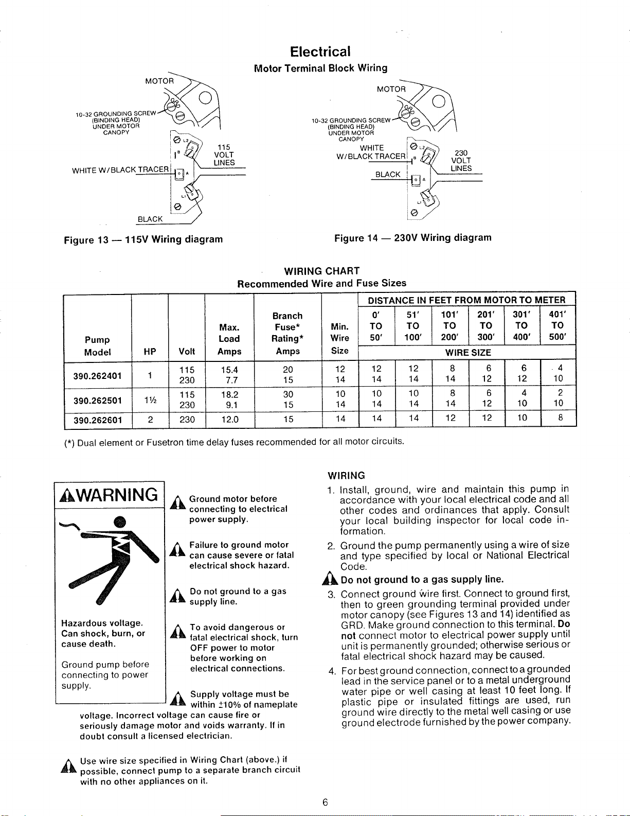
Electrical
Motor Terminal Block Wiring
MOTOR
10-32 GROU
(BINDING HEAD)
UNDER MOTOR
CANOPY
WHITE W/BLACK TRACER[ Io7, i X
BLACK _
115
VOLT
LINES
Figure 13 -- 115V Wiring diagram
10-32 GROU
(BINDING HEAD)
UNDER MOTOR
CANOPY
WHITE _ L_,
W/BLACK TRACER i s _
I
BLACK !IQ_ _
230
VOLT
\ LINES
Figure 14 -- 230V Wiring diagram
Pump
Model HP
390.262401 1
390.262501 1½
390.262601 2
WIRING CHART
Recommended Wire and Fuse Sizes
DISTANCE IN FEET FROM MOTOR TO METER
Volt
115
230
115
230
230
Max.
Load
Amps
15.4
7.7
18.2
9.1
12.0
Branch
Fuse*
Rating*
Amps
20
15
30
15
15
0' 51' 101' 201' 301' 401'
Min. TO TO TO TO TO TO
Wire 50' 100' 200' 300' 400' 500'
Size WIRE SIZE
12 12 12 8 6 6 - 4
14 14 14 14 12 12 10
10 10 10 8 6 4 2
14 14 14 14 12 10 10
14 14 14 12 12 10 8
(*) Dual element or Fusetron time delay fuses recommended for all motor circuits.
kWARNING
,_ Ground motor before
connecting to electrical
power supply.
,_ Failure to ground motor
can cause severe or fatal
electrical shock hazard.
A_IL Do not ground to a gas
supply line.
Hazardous voltage.
Can shock, burn, or ,_b,
cause death.
Ground pump before
connecting to power
supply,
,_ Supply voltage must be
within +10% of nameplate
voltage. Incorrect voltage can cause fire or
seriously damage motor and voids warranty. If in
doubt consult a licensed electrician.
To avoid dangerous or
fatal electrical shock, turn
OFF power to motor
before working on
electrical connections.
,_Use wire size specified in Wiring Chart (above.) it
possible, connect pump to a separate branch circuit
with no othe_ appliances on it.
WIRING
1. Install, ground, wire and maintain this pump in
accordance with your local electrical code and all
other codes and ordinances that apply. Consult
your local building inspector for local code in-
formation.
2. Ground the pump permanently using a wire of size
and type specified by local or National Electrical
Code.
_h, Do not ground to a gas supply line.
3. Connect ground _vire first. Connect to ground first,
then to green grounding terminal provided under
motor canopy (see Figures 13 and 14)identified as
GRD. Make ground connection to this terminal. Do
not connect motor to electrical power supply until
unit is permanently grounded; otherwise serious or
fatal electrical shock hazard may be caused.
4. For best ground connection,connecttoagrounded
lead in the service panel or to a metal underground
water pipe or well casing at least 10 feet long. If
plastic pipe or insulated fittings are used, run
ground wire directly to the metal well casing or use
ground electrode furnished by the power company.
Loading ...
Loading ...
Loading ...