Loading ...
Loading ...
Loading ...
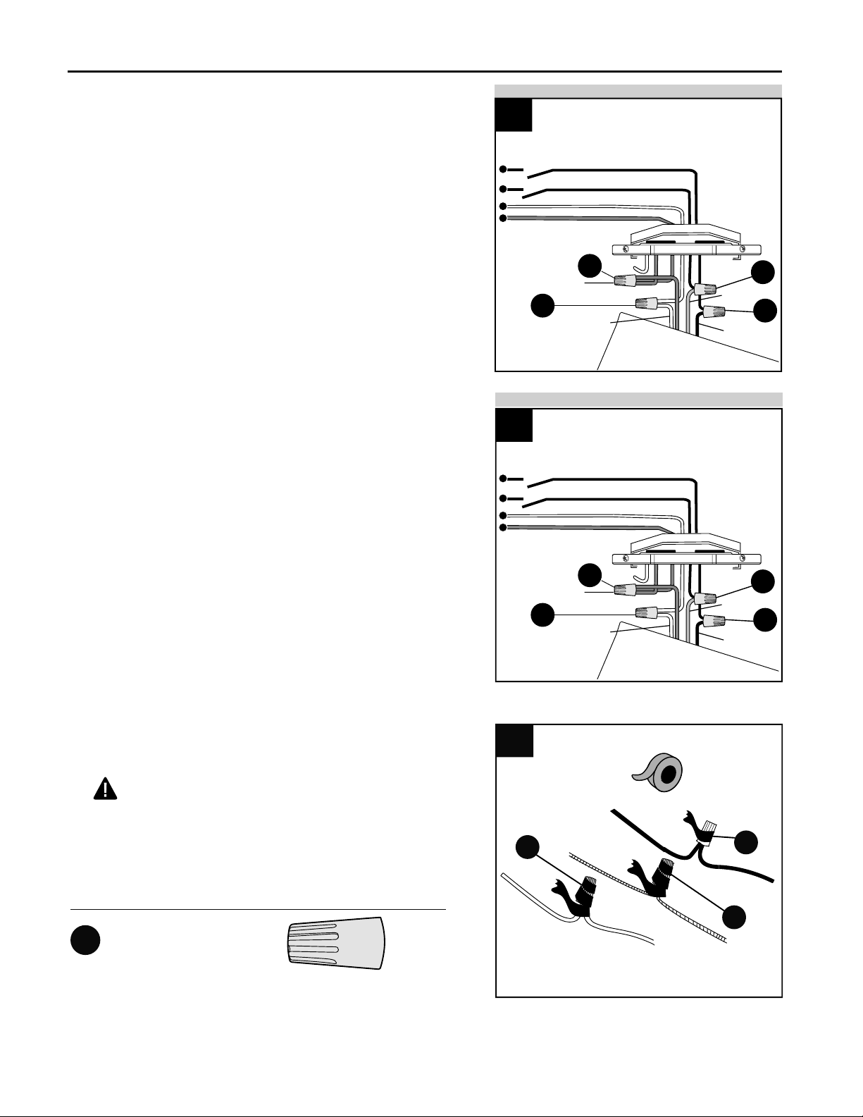
9
Wrap electrical tape (not included) around each
individual wire connector (CC) down to the wire.
WARNING: Make sure no bare wire or wire
strands are visible after making connections. Place
BARE/GREEN and WHITE connections on
opposite side of box from the BLACK and BLUE (if
applicable) connections.
2.
2.
CC
2
CC
CC
Hardware Used
Wire Connector
x 4
CC
WIRING
1b. FAN CONTROLLED BY PULL CHAIN, LIGHT
BY WALL SWITCH: Connect BLACK wire from fan
to BLACK wire from ceiling. Connect BLUE wire
from fan to the BLACK wire from the independent
wall switch for the light. Connect WHITE wire from
fan to WHITE wire from ceiling. Connect GROUND
(GREEN) wires from motor housing (B), if
applicable, and mounting plate (A) to
BARE/GREEN wire from ceiling.
FAN CONTROLLED BY PULL CHAIN, LIGHT BY WALL SWITCH
1b
BLACK
BLUE
120V POWER
FROM CEILING
BLACK (POWER)
BLACK (WALL SWITCH)
WHITE (NEUTRAL)
GROUND/GREEN (BARE)
GREEN
CC
CC
CC
CC
1c. FAN AND LIGHT CONTROLLED BY TWO
WALL SWITCHES: Connect BLACK wire from fan
to BLACK (or RED) wire from the independent
wall switch for the fan. Connect BLUE wire from
fan to the BLACK (or RED) wire from the other
independent wall switch for the light. Connect
WHITE wire from fan to WHITE wire from ceiling.
Connect GROUND (GREEN) wires from motor
housing (B) and mounting plate (A) to
BARE/GREEN wire from ceiling.
NOTE: BLACK wire is hot power for fan. BLUE wire
is hot power for light kit. WHITE wire is common for
fan and light kit. GREEN or BARE wire is ground.
BLACK (WALL SWITCH)
BLACK (WALL SWITCH FOR LIGHT)
FAN AND LIGHT CONTROLLED BY TWO WALL SWITCHES
FAN AND LIGHT CONTROLLED BY TWO WALL SWITCHES
1c
WHITE
BLACK
BLUE
120V POWER
FROM CEILING
WHITE (NEUTRAL)
GROUND/GREEN (BARE)
GREEN
CC
CC
CC
CC
WHITE
Loading ...
Loading ...
Loading ...