Loading ...
Loading ...
Loading ...
Maintenance
Owner’s Manual for 60 Hz Air-Cooled Generators 27
7. (11-22 kW units only): Verify that the air inlet duct
(D) is properly connected to the air cleaner cover.
8. Press the AUTO button on the control panel to
return the unit to AUTO mode.
Spark Plugs
Proceed as follows to check the spark plug(s) gap and
replace the spark plug(s) as necessary:
1. With the generator OFF and the engine cool, lift the
lid and remove the front panel.
2. Clean the area around the base of the spark
plug(s) to keep dirt and debris out of the engine.
3. Remove the spark plug(s) and check the condition.
Install a new plug(s) if the old plug(s) is worn or if
reuse is questionable.
4. Clean the plug(s) by scraping or washing with a
wire brush and commercial solvent. Do not blast
the plug(s) to clean.
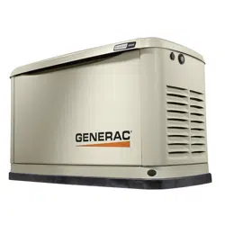
5. Check the spark plug gap using a wire feeler
gauge. See Figure 4-6. Replace the spark plug if
the gap is out of specification. See General
Information.
6. Reinstall the spark plug(s), and torque to 18.4 ft-lbs
(25 Nm).
7. Press the control panel AUTO button to return the
unit to AUTO mode.
Figure 4-6. Spark Plug Gap Measurement
Valve Clearance Adjustment
Check the valve clearance after the first 25 hours of
operation, then after 400 hour intervals. Adjust if
necessary.
Important: Please contact an IASD for service
assistance. Proper valve clearance is essential for
prolonging the life of the engine.
Check Valve Clearance
NOTE: The engine should be cool before checking the
valve clearance. Adjustment is not needed if valve
clearance is within the dimensions provided in
Specifications.
1. Close fuel valve and disconnect battery to avoid
accidental start-up.
2. Remove spark plug wires, and position wires away
from plugs.
3. Remove spark plugs.
4. Make sure the piston is at top dead center (TDC) of
its compression stroke (both valves closed). To
move the piston to TDC, remove the intake screen
at the front of the engine to access the flywheel
nut. Use a large socket and socket wrench to
rotate the flywheel nut clockwise, which will rotate
the crankshaft. Watch the piston through the spark
plug hole. The piston should move up and down.
The piston is at TDC when it is at its highest point
of travel.
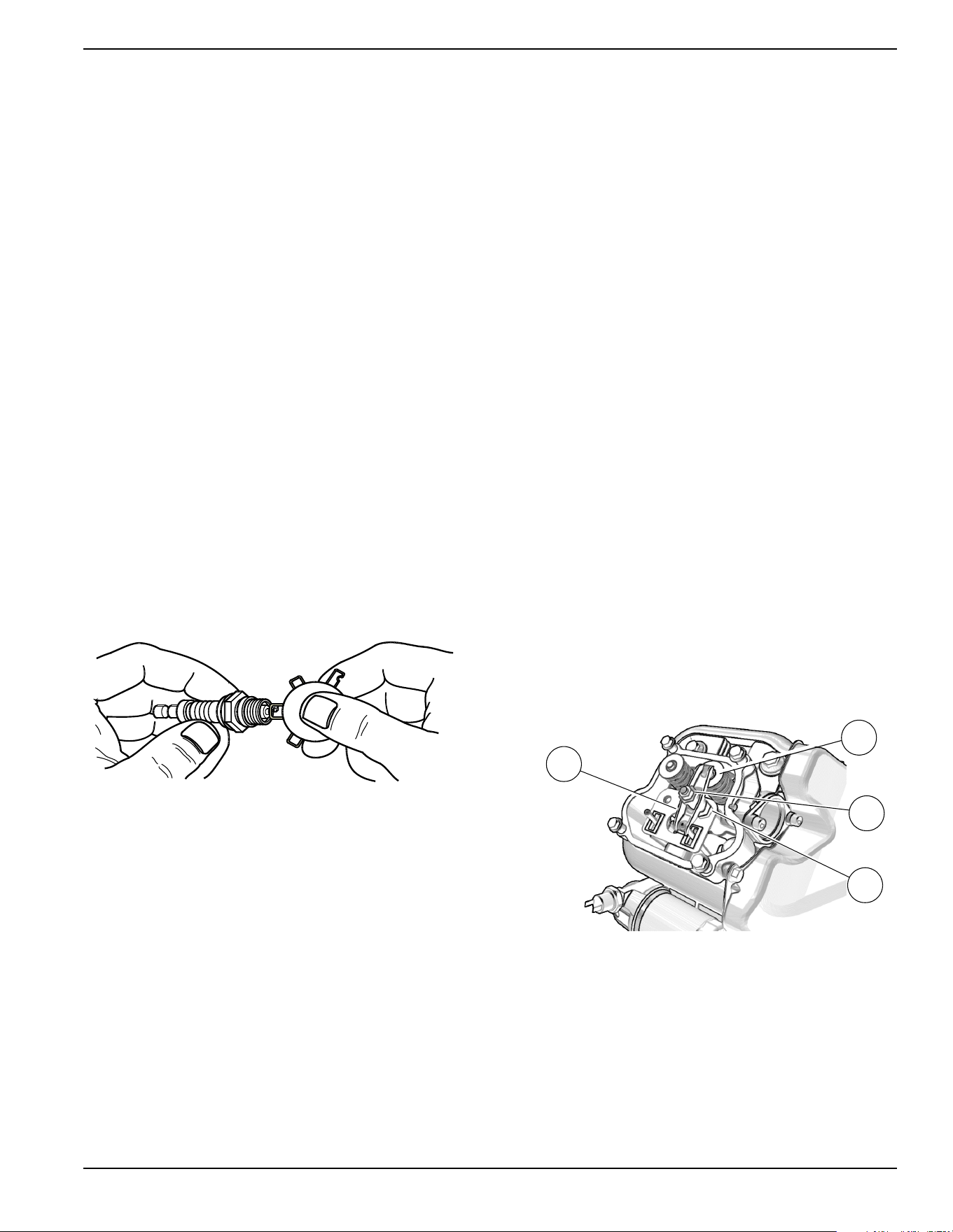
Adjust Valve Clearance
See Figure 4-7 or Figure 4-8. Proceed as follows to
adjust the valve clearance:
NOTE: Allow engine to cool before adjusting valve
clearance.
1. Make sure the piston is at top dead center (TDC) of
its compression stroke (both valves closed).
2. Remove spark plug wire(s) and position wire(s)
away from plugs.
3. Remove spark plug(s).
4. Remove the four screws attaching the valve cover.
Remove and discard gasket.
5. Loosen the rocker jam nut (C) using a 10 mm
wrench (9-11 kW units) or 13 mm wrench (16-22
kW units.)
.
Figure 4-7. Valve Clearance Adjustment (9 kW)
000211
001812
C
D
E
F
Loading ...
Loading ...
Loading ...