Loading ...
Loading ...
Loading ...
952.864UK, 952.867UK User Manual
Induction loop cable installation
Prior to installation, it is important to check if there will be any equipment in the vicinity that may interfere
with the loop’s magnetic field, such as large transformers, high power cables or substations. It is also
important to ensure that no equipment will be adversely affected by the loop field, such as sensitive data or
signal cables. In these cases, it may not be possible to cover some or any of the required area with an
induction loop.
The cable gauge will depend upon the total length of the induction loop. Usually, the loop will be installed
around the perimeter of the listening area. However, there are various techniques which can be employed to
build arrays to vary the shape and strength of the field. In general, calculations outlined here are based upon
a perimeter installation.
It is recommended to use good quality insulated pure copper cable for the induction loop. The cable gauge
used will need to be determined by the total length of the cable run. The LA-series loop amplifiers are
designed to operate with a load of between 0.2Ω and 2Ω. The following equation can be used to calculate
the total cable resistance, which will show if the gauge is correct.
R = Cable length (m) x 0.01786Ω*mm²/m (specific resistance of Copper)
Cable CSA (mm²)
So, for a cable 80m long with a Cross-Sectional Area (CSA) of 1.5mm²… R = 80/1.5 x 0.01786 = 0.9525Ω
So, this gauge of wire (1.5mm²) would be OK for the 80m run because it is between 0.2Ω and 2Ω
As a quick reference, refer to the table below.
Cable CSA (mm²)
1.0
1.5
2.5
4.0
Total Loop Length
60m max.
110m max.
200m max.
Over 200m
The wire may be run in plastic conduit but not in any metal containment so as not to impair the magnetic
flux. The ideal height to install the cable depends upon the width of the loop (i.e. the narrowest dimension
relative to the listener). The optimum output will be achieved if the cable is installed 14% of the loop width
higher or lower than the plane of listening (ear height).
In practical terms, the loop is usually installed onto skirting boards, under flooring or at ceiling height so that
it is unobtrusive. It is recommended to avoid varying height levels as much as possible to avoid anomalies in
field strength.
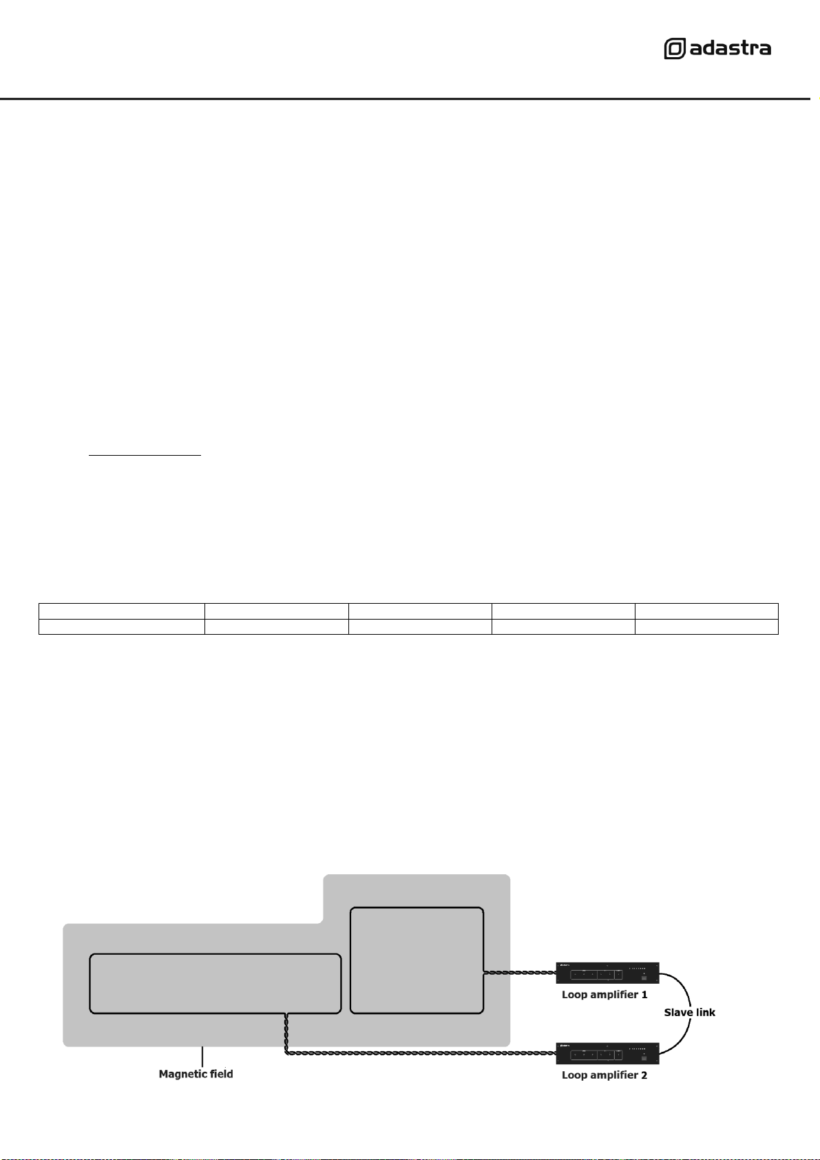
For irregular shaped areas or larger than the loop amplifier’s capacity, multiple induction loops may be
required for coverage. Connecting further loop amplifiers using the Slave connection will enable multiple
loops to be used together.
Loading ...
Loading ...
Loading ...