Owners
Manual
FOR POTABLEWATER
HEATING ONLY
NOT SUITABLEFOR
SPACEHEATING.
FOR USE ONLY IN
MOBILE HONES
Model No.
MODEL NUMBERS:
153.333831 30 Gal.
153.333931 40 Gal.
Caution:
Read and Follow
All Safety Rules and
Operating Instructions
Before First Use of
This Product.
Save this Manual for Future Reference.
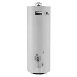
THE ECONOMIZERS5
MOBILE HOM
GAS WATER HEATER
• Safety Instructions
• Installation
• Operation
For Your Safety
• Care and Maintenance
• Troubleshooting
• Parts List
AN ODORANT IS ADDED TO THE GAS USED BY THIS
WATER HEATER
.WARNING: If the information in these instructions are not fol-
lowed exactly, a .fire or explosion may result, causing property
_Emage, personal mlury or death.
-"=Do not store or use gas.oline or other flammable vapors and liq-
uids in the vicinity of this or any other appliance.
-__6/HAT TO DO IF YOU SMELL GAS
• Do not try to light any appliance.
Do not touch any electrical switch; do not use any phone in your
building.
• Immediately call your gas supplier from a neighbor's phone.
Follow the gas sup lier'sinstructions.
• If you can not reac_ your gas supplier, call the fire department.
-Installation and service must be performed by a qualified installer,
i service agency or the gas supplier.
AWARNING
Improper installation, adjustment, alteration, service or maintenance
can cause DEATH, SERIOUS BODILY INJURY, OR PROPERTY DAM-
AGE. Refer to this manual for assistance or consult the local Sears
Service Center or gas utility for further information.
AWARNING J
Flammable vapors may be drawn by air currents from other areas
of the structure to this appliance.
_,WARNING
READ THE GENERAL SAFETY SECTION BEGINNING ON INSIDE
COVER AND THEN THIS ENTIRE MANUAL BEFORE INSTALLING
OR OPERATING THIS WATER HEATER.
Sears, Roebuck and Co., Hoffman Estates, IL 60179 U.S.A.
Safety Precautions
AWARNING
Improper installation, adjustment, alteration, service or
maintenance can cause DEATH, SERIOUS BODILY
INJURY,OR PROPERTYDAMAGE. Refer tothis manualfur
assistanceor consult your local SearsService Center fur
further nfurmation.
AWARNING
WATER HEATERSEQUIPPEDFOR ONE TYPE GAS ONLY:
Thiswaterheateris equippedfur one typegasonly.Checkthe
modelratingplatenear the gascontrolvalvefur the correctga_
DONOT USETHISWATERHEATERWITH ANY GASOTHER
THAN THE ONE SHOWN ON THE MODELRATINGPLATE.
Failureto usethe correctgascancauseproblemswhichcan
result in DEATH,SERIOUSBODILY INJURY,OR PROPERTY
DAMAGE.Ifyouhaveanyquestionsor doubtsconsultyourgas
supplierorlocalutility.
AWARNING
INSTALLATIONSIN AREASWHERE FLAMMABLELIQUIDS
(VAPORS) ARE LIKELY TO BE PRESENT OR STORED
(GARAGES, STORAGE, AND UTILITY AREAS, ETC):
Flammableliquids(suchas gasoline,solvents,propane(LP)or
butane, etc.), all of whichemit flammable vapors,maybe
improperlystoredor usedin suchareas.The gaswaterheater
pilotlightor main burnercanignitesuchvapors.The resulting
flashbackandfirecancausedeathor seriousburnsto anyonein
the area,aswellaspropertydamage.
Ifinstallationinsuchareasisyouronlyoption,then the installa-
tion mustbe accomplishedin a way that the pilotflame and
mainburnerflameareelevatedfromthe floorat least18inche_
While thismayreducethechangesofflammablevaporsfroma
floorspillbeingignited,gasolineandotherflammablesubstances
shouldneverbestored or usedin the sameroomor areacon-
taininga gaswaterbeateror otheropenflameor sparkproduc-
ingappliance.
NOTE:Flammablevaporsmay be drawnbyair currentsfrom
otherareasofthestructuretotheappliance.
AWARNING
Ifthiswater heaterwillbeusedinbeautyshops,barbershops,
cleaningestablishments,or self-servicelaundrieswith dry
cleaningequipment,it isimperativethat the water heateror
water heatersbe installedsothat combustionand ventilation
air be takenfrom outsidethese areas.Referto the "Factsto
ConsiderAboutthe Location"section ofthis manualand also
the latesteditionofthe NationalFuelGasCode,ANSI Z223.1,
alsoreferred to as NFPA54 for specificsprovidedconcerning
air required.
I AWARNING 7
A fire can start if combustible materials suchas clothing,I
cleaningmaterials, or flammable liqwdsare placedagainst[
or next to the water heater. |
AWARNING
At the time of manufacturethis water heater wasprovided
with acombinationtemperatore-pressuresreliefvalvecertified
bya nationally recognized testinglaboratorythat maintains
periodicinspec_onofproductionoflistedequipment or mate-
rials, as meeting the requirements for Relief Valvesand
AutomaticGasShutoffDevicesforHot Water SupplySystems,
and the latest editionof ANSI Z21.22 and the coderequire-
mentsofASME.If replaced,thevalvemustmeet the require-
meritsoflocalcodes,but notlessthan acombinationtempera-
tore and pressurereliefvalvecertifiedasmeetingthe require-
mentsfor ReliefValvesandAutomaticGasShutoffDevicesfur
Hot Water SupplySystems,ANSIZ21.22byanationally recog-
nizedtestinglaboratorythat maintainsperiodicinspectionof
productionoflistedequipmentor materials.
The valvemustbe markedwith a maximumset pressurenot
to exceedthe marked hydrostaticworking pressureof the
water heater(150IbsJsq.in.)and a dischargecapaclt);not less
thanthewater heaterinputrateasshownonthe model rating
plate.(Electricheaters- watts dividedby 1000x 3415 equal
BTU/Hr.rate.)
Yourlocaljurisdictionalauthority,whilemandatingtheuseofa
temperature-pressurereliefvalvecomplyingwith ANSI Z21.22
andASME,may requirea valvemodeldifferentfromthe one
furnishedwiththewater heater.
Compliancewith suchlocalrequirements mustbesatisfiedby
theinstalleror enduserofthewater heaterwith a locallypre-
scribedtemperature-pressurereliefvalveinstalledinthe desig-
natedopeninginthe water heaterin placeofthe factoryfur-
nisbedvalve.
Forsafeoperationofthewaterheater,therelief valve"inustnot
beremovedfromit'sdesignatedopeningor plugged.
The tempe ' m..st be installeddirectly
intothe fitti_ter heaterdesignatedforthereliefvalve.
Positionthe valvedown--tubing sothatanydis-
chargewill__ll_r above,or at anydistance
belowthe structuralfloor.Becertainthat no contactismade
withanyliveelectricalpa_ee-T4_vd_hargeopeningmustnot be
blockedor reducedin sizeunderanycircumstances.Excessive
length,ove_'nlore-than fourelbowscancause
restriction and.re.dur.___the_ddiscbargecapacityofthevalve.
No valveor otherobstruction_is't_beplacedbetweenthe relief
valveandthe-eanl¢-Do-not.coonect..Zubing_diJ'oectlyto discharge
drainunlessa 6"air gapisprovided.Topreventbodilyinjury,haz-
ardto life,or propertydamage,the reliefvalvemustbeallowed
todischargewaterinquantitiesshouldcircumstancesdemand.If
the dischargepipeisnotconnectedto a drainor othersuitable
means,thewaterflowmaycausepropertydamage.
The DischargePipe:
Mustnot be smallerin sizethan the outletpipesizeof the
valve,orhaveanyreducingcouplingsor otherrestrictions.
Mustnot bepluggedor blocked.
Mustbeofmateriallistedfor hotwaterdistribution.
Must beinstalledsoasto allow completedrainageof both
the temperatore-pressurerelief valve,and the discharge
pipe.
Mustterminateat anadequatedrain.
Mustnot haveanyvalvebetweentherelief valveandtank.
Safety Precautions
AWARNING
A gaswater heatercannotoperateproperlywithoutthe cor-
rectamountofairfor combustion.Do not installina confined
areasucha doset,unlessyouprovideair asshowninthe"Facts
to ConsiderAbout the Location"sectior_Never obstructthe
flowofventilationair.Ifyouhaveanydoubtsor questionsat all,
callyour gascompany.Failureto providetheproperamountof
combustionair canresultin a fire or explosionand cancause
DEATH,SERIOUSBODILYINJUI_,ORPROPERTYDAMAGE.
AWARNING
Thiswater heatermustnot be installeddirectlyon carpeting.
Carpeting must be protected by a metal or wood panel
beneath the applianceextendingbeyondthe full width and
depth ofthe appliance.byat least3 inches(76.2mm) in an)
direction,or If the apphanceisinstalledin an alcoveor deset
the entirefloormustbe coveredby the panel.Failureto heec
thiswarningmayresultina firehazard.
AWARNING
HOTTER WATERCAN SCALD:Water heatersareintended.to
producehot water,Water heatedto a temperaturewhichwill
satisfyclotheswashing_dishwashin_and othersanitizingneeds
canscaldand permanentlyinjure youuponcontact.Somep_-
pieare morelikelytobepermanentlyinjuredbyhotwaterthan
others_Theseincludethe elderly,children,theinfirm,orphysical-
ly/mentallyhandicapped.Ifanyoneusinghotwaterinyour home
fitsintooneofthesegroupsor ifthereisa localcodeor statelaw
requiringa certaintemperaterewater atthehotwater ta_ then
youmusttakespecialprecautions.Inadditionto usingthe lowest
possibletemperaturesettingthatsatisfiesyourhot waterneeds
a meanssuchasa mixingvalve,shouldbe usedat the hotwater
tapsusedby thesepeopleor at the water heater.Mixingvalves
areavailableat plumbingsupplyorhardwarestores.Followman-
ufacturersinstructionsfor installationof the valves.Before
changingthe factory setting on the thermostat, read the
'q'emperatureRegulation"sectioninthismanual.
AWARNING ]
Soot build-upindicat_t requirescorrection/
beforefurther use.Turn"OFF" gasto water heaterand lea_veI
"OFF" until repairs are made, becausefailureto correctthe|
causeof the sootingcanresult in a fire or explosioncausing|
DEATH,SERIOUSBODILYINJUI_,ORPROPERTYDAMAGE./
AWARNING
VENT DAMPERS- Any ventdamper,whether it is operated
thermallyor otherwisemustberemovedifitsuseinhibitsprop-
erdraftingofthe water heater.
ThermallyOperatedVent Dampers:Gas-firedwater heaters
havingthermalemciencyin excessof 80%may producea rela-
tivelylowfluegastemperature.Suchtemperaturesmaynot be
high enough to properly open thermally operated vent
damper_This wouldcausespillageoffluegasesandmaycause
carbonmonoxidepoisoning.
Ventdampersmustbearevidenceofcertificationascomplying
with the latestedition ofAmerican NationalStandardANSI
Z2h68 (ANSI Z21.66& 67,respectively,coverelectricallyand
mechanicallyactuatedventdampers).Beforeinstallationofany
vent damper,consultyourlocalSearsServiceCenterorthe gas
utilityfor furtherinformation.
AWARNING
• The applianceanditsindividualshutoff valvemustbediscon-
nected fromthe gassupplypipingsystemduringanypressure
testing ofthe gassystem at test pressuresin excessof '/
poundper squareinch(3.5kPa).
•The appliancemustbe isolatedfromthe gassupplypipingsys
tem by closingitsindividualmanualshutoffvalveduringany
pressuretestingofthe gassupplypipingsystemat test pres-
seresequalorlessthan '/zpoundpersquareinch(3.5kPa).
a, WARNING
BEFORELIGHTING PROPANE(LR) GASWATERHEATERS:
Propane(L.P.)gasisheavierthan air.Shouldthere be a leakin
the system,the gaswill settle near the ground.Basements,
crawlspaces,skirtedareasundermobile homes(evenwhen
ventilated),closetsand areasbelow groundlevelwill serveas
pocketsfor the accumulationofthisga_Beforeattemptingto
lightor relight the water heater'spilotor turningon a nearby
electricallightswitch,be absolutelysurethere isno accumulat-
ed gasinthe areL Searchfor odorof gasby miffingat ground
levelinthe vicinityof the appliance.If odor isdetected,follow
stepsindicatedat "For YourSafety"on the coverpageofthis
manualthenleavethepremises.
AWARNING
Chemical vaporcorrosionof the flue and vent system may
occurif air for combustioncontainscertainchemicalvapors.
Spraycanpropellants,cleaningsolvents,refrigerator andair
conditionerrefri.gerants,swimming pool chemicals,calcium
andsodiumchloride,waxes,bleach,and processchemicalsare
typicalcompoundswhicharepotentiallycorrosive.
AWARNING
Obstructedor deterioratedvent systemsmaypresenta serious
healthriskor asphyxiation.
Safety Precautions continued on page 4
Safety Precautions
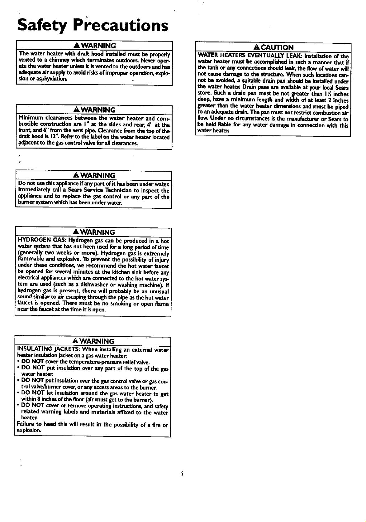
I AWARNING ]
The water heater with_stailed mustbeproperlyI
ventedto a chimneywhichterminatesoutdoor_Neveroper-I
acethe waterheaterunlessitisventedto the outdoorsandhasI
.aclequa_m,'r_ to avoidrisksofimproperoperation,explo-I
stunor aspnyxmuoo. . ]
&WARNING 1
Minimum clearances_ter heater and tom-I
hustibleconstructionare I" at the sidesand rear,4" at theI
front,and6"fromthe ventpipe.Clearance&orethetop ofthe [
drafthoodis12".Referto the labelonthewaterheaterlocatedI
_adjacentto the gascontrol_ foralldearance_ J
_WARNING 1
Do not usethis applianceifanypart ofit hasbeenunderwater.|
Immediately call a SearsServiceTechnicianto inspectthe|
applianceand to replace the gascontrol or any part ofthe/
burnersystemwhichhasbeenunderwater. I
A CAUTION
WATER HEATERSEVENTUALLY LEAK:Installationofthe
water beater mustbe accomplishedin sucha mannerthat if
the tankor anyconnectionsshouldleak,the flowofwater will
tbe u. re. When ,o ons
not be avoided,a suitabledrampan shouldbe installedunder
tbe wa_erbeater. Drein pansare availableat yourlocalSears
store.Sucha drain pan mustbe not greaterthan I_ inches
deep,havea minimum lengthandwidth of at least2 inches
greatertfian the water heaterdimensionsandmustbe piped
toan adequatedrain.The panmustnotrestrictcombustionair
flow.Under no circumstancesisthe manufactureror Searsto
be heldliablefor anywater damagein connectionwith this
water heater.
_,WARNING
HYDROGEN GAS:Hydrogengascanbe producedin a hot
water systemthat hasnot beenusedfor alongperled of tlme
(generallytwo weeksor more). Hydrogengasisextremely
flammableand explosive.To preventthe possibilityof injury
underthese conditions,we recommendthe hot water faucet
be openedfor severalminutesat the kitchensinkbeforeany
electricalapplianceswhich am connectedto the hotwatersys-
tem are used(suchasa dishwasheror washingmachine). If
hydrogengasispresent, there will probably be an unusual
soundsimilartoair escapingthrough the pipeasthe hotwater
faucetisopened.There must be no smokingor openflame
nearthe faucetatthe time itisopen.
_iLWARNING
INSULATING JACKETS=When installingan externalwater
heaterinsulationjacketona gaswater heater:
• DO NOT coverthe temperature-pressurereliefvalve.
• DO NOT put insulationover anypart of the top of the gas
waterheater.
I DO NOT putinsulationoverthe gascontrolvalveor gascon-
trolvalveJbureercover,or anyaccessareasto the burner.
DO NOT let insulation aroundthe gaswater heaterto get
within8 inchesofthe floor(air mustget tothe burner).
• DO NOT coveror remove operatinginstructions,andsafety
related warninglabelsand materials amxedto the water
heater.
Failureto heedthis will result in the possibilityof a fire or
explOSiOn,
Table of Contents
q¢="'_,a,_yPrecautions ............................................................................................................................................2-4
Table of Contents ..........................................................................................................5
Customer
Kesponslbllltles .......................................................................................................................6
Product Specifications ....................................................i.............................................................................6
Materials and Basic Tools Needed ...............................................................................................7
Materials Needed ...................................................................................................................................................................... 7
BasicTools ................................................................................................................................................................................ 7
Installation Instructions ........................................................................................................................8-18
Removing the Old Water Heater ............................................................................................................................................... 8
Factsto Consider About the Location............................ ...................................................................................................... 9-10
Securing Water Heater to Floor and Wall ................................................................................................................................ 11
Water Piping ..................... ._........................................................................ ....................................................................... 11-1
Temperature-Pressure RaeliefValve ........... 13
Filling the Water Heater .......................................................................................................................................................... 14
Venting .............................................................................................................................................................................. 14-15
Gas Piping .............................................................................................................................................................................. 15
_Fuel Conversion Instructions .......................................................................................................................................... 16-17
Installation Checklist .............................................................................................................................................................. 18
"""Uperatmg Instructions .........................................................................................................................19-21
Eighting ............................................................................................................................................................................. 19-20
Temperature Regulation.......................................................................................................................................................... 21
Service
and
A I.
Alljustment ......................................................................................................................22-23
Tank (Sediment) Cleaning ..................... 22
Burner Inspection ................................................................................................................................................................... 22
Burner Cleaning ..................................................................................................................................................................... 22
Draining ................................................................................................................................................................................. 22
Temperature-Pressure ReliefValve Operation .......................................................................................................................... 23
Drain ValveWasher Replacement ........................................................................................................................................... 23
Housekeeping ..................... :................................................................................................................................................... 23
Service .................................................................................................................................................................................... 23
Troubleshooting Guide ........................................................................................................................24-2;
Start Up Conditions ............................................................................................................................................................... 24
Thermal Expansion ............................................................................................................................................................... 24
Strange Sounds ..................................................................................................................................................................... 24
Condensation ....................................................................................................................................................................... 25
Smoke/Odor ......................................................................................................................................................................... 25
Operational Conditions ..................................................................................................................................................... 25-26
Smdly Water ......................................................................................................................................................................... 25
Air in Hot Water Faucets...................................................................................................................................................... 25
High Temperature Shut OffSysrem ...................................................................................................................................... 26
Not Enough Hot Water ........................................................................................................................................................ 26
Water is too Hot ................................................................................................................................................................... 26
Leakage Checkpoints .............................................................................................................................................................. 27
Parts Order List ...............................................................................................................................................28-29
Customer Responsibilities
Thank You for purchasing a Sears water heater.
Properly installed and maintained, it should give you years of
trouble free service. If you should decide that you want the new
water heater professionally installed by Sears cal! the local Sears
Service Center or any Sears store. They will arrangefor prompt,
quality installation by Sears'authorized contractors.
Abbreviations Found In This Instruction Manual
A.G.A. - American Gas Association
A.N.S.I. - American National Standards Institute
N.EEA. - National Fire Protection Agency
The gas fired water heater is design certified by the
American Gas Association Laboratories under
American National Standards for Gas Water
Heaters for Installation in Manufactured Houses,
(Mobili_ Homes).
Instructions to Mobile Home Manufacturers:
The installation must conform with the
Manufactured Home Construction and Safety
Standard for Mobile Home Construction and Safety
Title 24 CFR, Part 3280 (Formerly the Federal
Standard for Mobile Construction and Safety Title
24 (Part 280), 1975.
Instruction for replacement installation:
The installation must conform with the instructions
in this manual; gas company rules; and Local Codes,
or in the absence of Local Codes, with the latest edi-
tion of the National Fuel Gas code, ANSI Z223.1,
also referred to as NFPA 54. This publication isavail-
able from your local government or public library or
gas company or by writing NFPA, Batterymarch
Park, Quincy, MA 02269.
• Read the "Safety Precautions" section, pages 2 through 4 of
this manual first and then the entire manual carefully. If you
don't follow the safety rules, the water heater will not operate
properly. It could cause DEATH, SERIOUS BODILY
INJURY AND/OR PROPERTY DAMAGE.
This manual contains instructions for the installation, opera-
tion, and maintenance of the gas-fired water heater. It also
contains warnings through out the manual that you must
read and be aware of. Allwarnings and all instructions are
essential to the proper operation of the water heater and your
safety. Since we cannot put everything on the first few pages,
READ THE ENTIRE MANUAL BEFORE ATTEMPTING
TO INSTALL OR OPERATE THE WATER HEATER.
The gas fired water heater is design certified by the American
Gas Association Laboratories under American National
Standards for Gas Water Heaters for Installation in
ManufacturedHouses, (Mobile Homes).
Instructions to Mobile Home Manufacturers:
The installation must conform with the ManufacturedHome
Construction and Safety Standard for Mobile Home
Construction and Safety Title 24 CFR, Part 3280 (Formerly
the Federal Standard for Mobile Construction and Safety Title
24 (Part 280), 1975.
Instruction for replacement installation:
The installation must conform with the instructions in this
manual; gas company rules; andLocal Codes, or in the absence
of Local Codes, with the latest edition of the National Fuel Gas
code, ANSI Z223.1, also referred to asNFPA 54. This publica-
tion is available from your local government or public library
or gas company or by writing NFPA, Batterymarch Park,
Quincy, MA 02269.
If afterreading this manual you have any questions or do not
understand any portion of the instructions, call the Sears
Service Center.
Carefully plan the place where you are going to put the water
heater. Correct combustion, vent action, andvent pipe instal-
lation are very important in preventing death from possible
carbon monoxide poisoning and fires.
Examine the location to ensure the water heater complies with
the _Facts to Consider About the Location" section in this
manual.
For California installation this water heater must be braced,
anchored, or strapped to avoid falling or moving during an
earthquake. See instructions for correct installation proce-
dures. Instructions may be obtained from your local dealer,
wholesaler, public utilities or California Office of the State
Architect, 400 P Street, Sacramento, CA 95814.
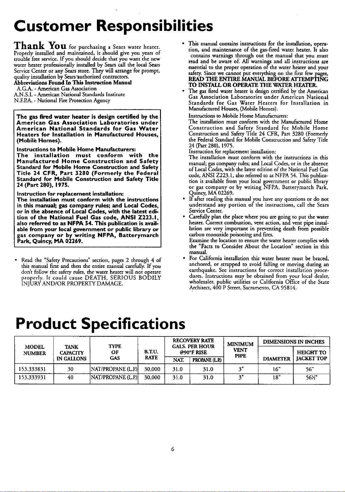
Product Specifications
MODEL
NUMBER
TANK
CAPACITY
IN GALLONS
TYPE
OF
GAS
B.T.U.
RATE
MINIMUM
VENT
PIPE
RECOVERY RATE
GALS. PER HOUR
@90°F RISE
NAT. PROPANE(LP.)
31.0 31.0
31.0 31.0
153.333831 30 NAT/PROPANE(LP.) 30,000 Y'
153.333931 40 NAT/PROPANE(L.P.) 30,000 3"
DIMENSIONS IN INCHES
HEIGHT TO
DIAMETER JACKET TOP
16" 56"
18" 56½"
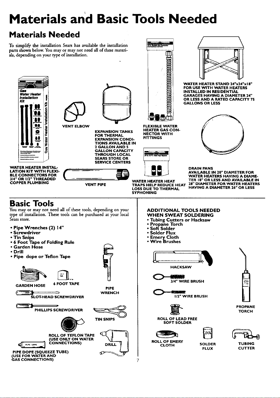
Materials and Basic Tools Needed
Materials Needed
To simplify the installation Sears has available the installation
parts shown below. You may ormay not need all of these materi-
als, depending on your type ofinstaUation.
Water Heater
Installation
Kit
IXIBLE V_
_TER GA
._TOR WI
FITTINGS
VENT ELBOW FLEXIBLE WATER
EXPANSION TANKS HEATER GAS CON-
FOR THERMAL NECTOR WITH
EXPANSION CONDI-
TIONS AVAILABLE IN
2 GALLON AND 5
GALLON CAPACITY
THROUGH LOCAL
SEARS STORE OR
SERVICE CENTERS
WATER HEATER INSTAL-
LATION KIT WITH FLEXI-
BLE CONNECTORS FOR
314" OR I/2" THREADED
COPPER PLUMBING
WATER HEATER STAND 24"x24"xl 8"
FOR USE WITH WATER HEATERS
INSTALLED IN RESIDENTIAL
GARAGES HAVING A DIAMETER 24"
OR LESS AND A RATED CAPACITY 75
GALLONS OR LESS
VENT PIPE
DRAIN PANS
AVAILABLE IN 20" DIAMETER FOR
WATER HEATERS HAVING A DIAME-
WATER HEATER HEAT TER 18" OR LESS AND AVAILABLE IN
TRAPS HELP REDUCE HEAT 28" DIAMETER FOR WATER HEATERS
LOSS DUE TO THERMAL HAVING A DIAMETER 26" OR LESS
SYPHONING
Basic Tools
You may or may not need all of these tools, depending on your
type of installation. These tools can be purchased at your local
Searsstore.
• Pipe Wrenches (2) 14"
• Screwdriver
• Tin Snips
• 6 Foot Tape of Folding Rule
• Garden Hose
• Drill
• Pipe dope or Teflon Tape
GARDEN HOSE 6 FOOT TAPE
SLOT-HEAD SCREWDRIVER
PIPE
WRENCH
PHILLIPS SCREWDRIVER
ROLL OF TEFLON TAPE
(USE ONLY ON WATER
CONNECTIONS)
PIPE DOPE (SQUEEZE TUBE)
(USE FOR WATER AND
GAS CONNECTIONS)
TIN SNIPS
DRILL
ADDITIONAL TOOLS NEEDED
WHEN SWEAT SOLDERING
• Tubing Cutters or Hacksaw
• Propane Torch
• Soft Solder
• Solder Flux
• EmeryCIoth
• Wire Brushes
HACKSAW
3/4" WIRE BRUSH
112"WIRE BRUSH
ROLL OF LEAD FREE
SOFT SOLDER
PROPANE
TORCH
ROLL OF EMERY
CLOTH SOLDER TUBING
FLUX CUTTER

Installation Instructions
Removing the Old Water Heater
Turn _OFF" the gas supply to the water heater.
AWARNING
If the main gas line shutoff serving all gasappliancesis
used,alsoshut "OFF" the gasat eachappliance. Leaveall
gasappliances shut "OFF" until the water heater installa-
tion s compete.
Turn water to water
"OFF" the the
heater. Some installations require that
the water be turned off to the entire
house.
Q Check again to make sure the gas supply
is "OFF" to the water heater. Then dis-
connect the gas supply connection from
the gas control valve.
®
(3
Attach a to water heater drain
hose the
valve and put the other end in a floor
drain or outdoors. Open the water
heater drain valve. Open a nearby hot
water faucet which will relieve pressure
in the water heater and speed draining.
Disconnect the vent pipe from the draft hood where
they connect to the water heater. In most installations
the vent pipe can be lifted off afterany screw or other
attached devices are removed. Dispose of the draft
hood. The new water heater has the draft hood which
must be used for proper operation.
Q a.
If you have copper piping to the water
heater, the two copper water pipes can
be cut with a hacksaw approximately 4"
away from where they connect to the
water heater. This will avoid cutting off
the pipes too short. Additional cuts can
be made later if necessary. Disconnect
the temperature-pressure relief valve
drain line. When the water heater is
drained, disconnect the hose from the
drain valve. Close the drain valve. The
water heater is now completely discon-
nected and ready to be removed.
Qb.
If you have galvanized pipe to the water
heater, loosen the two ga-lvanized pipes
with a,pipe wrench at the union in each
line. _so disconnect the piping remain-
ing to the water heater. These pieces
should be saved since they may be need-
ed when reconnecting the new water
heater. Disconnect the temperature-pres-
sure relief valve drain line. When the
water heater is drained, disconnect the
hose from the drain valve. Close the
drain valve. The water heater is now
completely disconnected and ready to be
removed.
AWARNING I
The water passing out of the drain valve may be extremely I
hot. To avoid being scalded, make sure all connections are I
tight and that the water flow is directed away from any
person.
ACAUTION I
Mineral buildup or sediment may have accumulated in the I
old water heater. This causes the water heater to be much I
heavier than normal and this residue, if spilled out, could
cause staining.
Installation Instructions (cont'd)
Facts to Consider About the
Location
Whether replacing an old water heater or putting the water
heater in a new location, the following criti.c,71points must be
observed.
This mobile home gas-fired water heater is for use in a mobile
home. You should carefully choose an indoor location for the
new water heater, because the placement is a very important
consideration for the safety of the occupants in the building
and for the most economical use of the appliance. This water
heater is for use only in mobile homes and is not intended
.for outdoor installation.
-ENCLOSURE INSTALLATIONS:
"The installation of this water heater must be within an
=endosure so as to separate the appliance combustion sys-
tem and venting system from the interior atmosphere of the
mobile home. There shall not be any door, removable
access panel, or other opening into the endosuse from the
inside of the mobile home. This water heater must be
installed using Method A or B.
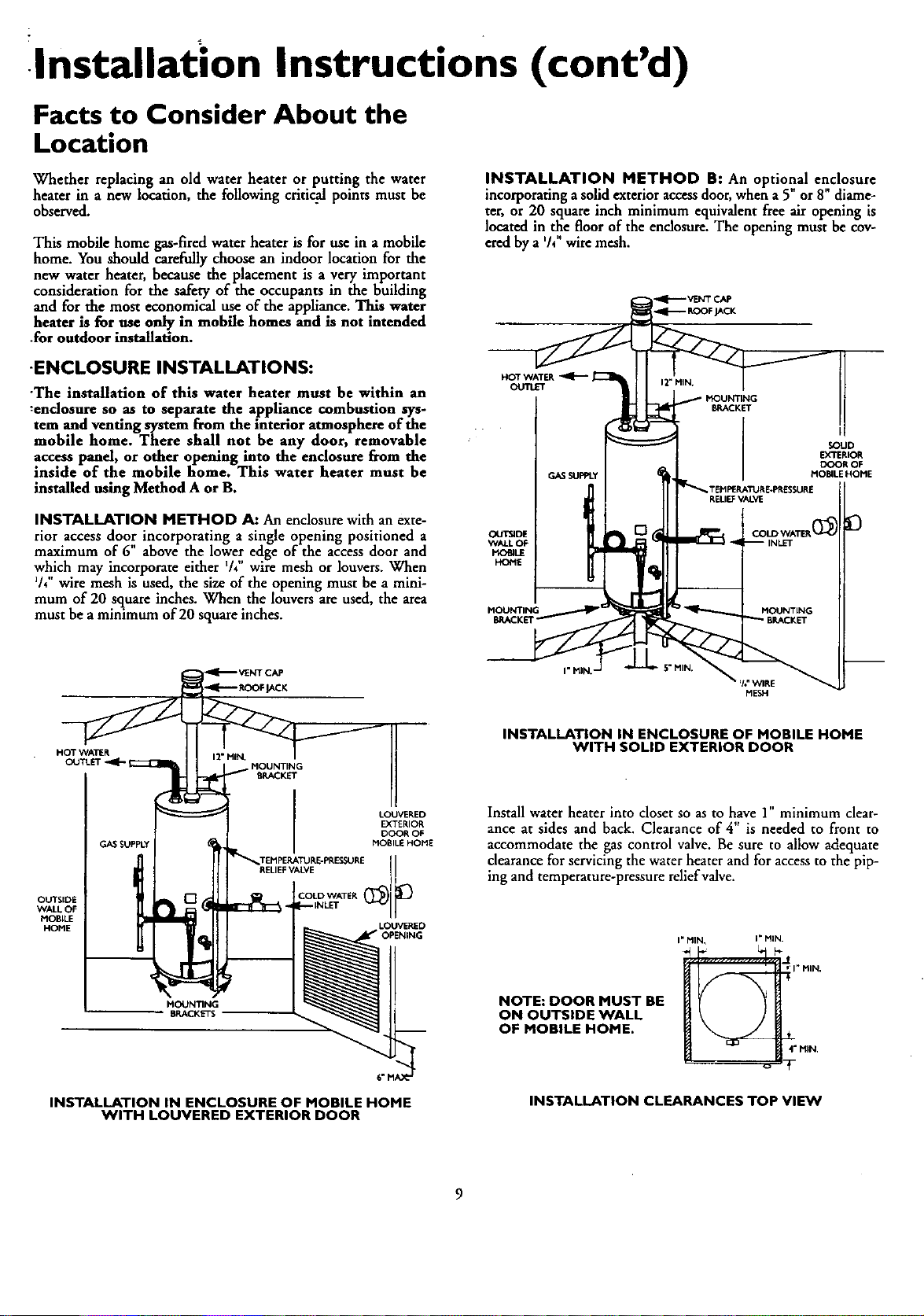
INSTALLATION METHOD A: An enclosurewith an exte-
rior access door incorporating a single opening positioned a
maximum of 6" above the lower edge of the access door and
which may incorporate either V+"wire mesh or louvers. When
V4"wire mesh is used, the size of the opening must be a mini-
mum of 20 square inches. When the louvers are used, the area
must be aminimum of 20 square inches.
INSTALLATION METHOD B: An optional enclosure
incorporating a solid exterior access door,when a 5 or8" diame-
ter, or 20 square inch minimum equivalent free air opening is
located in the floor of the endosure. The opening must be cov-
ered by a '/4"wire mesh.
HOT WATER
OUTLET
GAS SUPPLY
SOUD
DO'SRtOR
DOOR OF
MOBILEHOME
OUTSIDE
WALLOF
HOBILE
HOME
MOUNTING
OUTSIDE
WALL OF
MOBILE
HOME
HOT WATER
OUTLET
MOUNTING
BRACKET
GAS SUPPLY _111 !
BRACKETS
INSTALLATION IN ENCLOSURE OF MOBILE HOME
WITH LOUVERED EXTERIOR DOOR
INSTALLATION IN ENCLOSURE OF MOBILE HOME
WITH SOLID EXTERIOR DOOR
Install water heater into closet so as to have 1" minimum clear-
ance at sides and back. Clearance of 4" is needed to front to
accommodate the gas control valve. Be sure to allow adequate
clearance for servicing the water heater and for access to the pip-
ing and temperature-pressure reliefvalve.
NOTE: DOOR MUST BE
ON OUTSIDE WALL
OF MOBILE HOME.
I" MIK I" MIN.
I" HIM,
4" MIN.
INSTALLATION CLEARANCES TOP VIEW
9
Installation Instructions (cont'd)
Facts to Consider About the
Location (cont'd)
AWARNING
Minimum clearancesbetween the water beater and com-
bustibleconstructionare I" at the sidesand rear,4" at the
front,and6"from theventpipe.Clearancefromthe topofthe
acketis12"on mostmodelsNote that a lesserdimensionmay
be allowedon somemodels.Referto the abe on the water
beateradjacentto the gascontrolvalveforallclearance_
The water heater should be secured to the floor and to the wall
of the enclosure with the mounting brackets provided. For
bracket location refer to "Securing Water Heater to Floor and
Wall" in the "Installation Instructions" section.
When a mobile home is skirted, an air ifitake opening with a
minimum flee area of 32 square inches must be provided in the
skirt. If the opening is covered by louvers or screen, the totalfree
area must be 32 square inches. Other gas firedappliances in the
home will require additional free air openings; consult these
manufacturers for correct sizing.
AWARNING
A gaswater heatercannotoperateproperlywithoutthe cor-
rect amountofairfor combustion.Do not installin a confined
areasucha closet,unlessyouprovideairasshowninthe "Facts
to ConsiderAbout the Location"sectionon page9. Never
obstructthe flow of ventilationair.If you haveanydoubtsor
questionsat all,callyourgascompanyor SearsServiceCenter
Failureto providethe properamountof combustionair can
result in a fire or explosionand cancauseDEATH, SERIOUS
BODILYINJUI_,ORPROPERTYDAMAGE.
AWARNING
When the system requires water at temperatures higher than
required for other uses,the hot water system may require a
means such as a mixing valve to be installed to temper the
water at certain points of use. Some peop!e are more likely to
be permanently injured by hot water than others; these include
the elderly, children,the infirm, or the physically/mentallyhand-
icapped.Before immersing yourself or anyone elsein hot water,
be sure to check the water temperature. WARNING: HOT-
TER WATER INCREASES THE RISK OF SCALD INJURY.
(Also see "Temperature Regulation" section) Mixing valvesare
availableat plumbing supplyor hardware stores. Followmanu-
facturers instructionsfor installation of these valves.
AWARNING
Thiswater heater shallnot be connectedto anyheatingsys-
temsorcomponent(s)previouslyusedwitha nonpotablewater
heatingappliance.
AWARNING
If this water heater will be usedin beauty shops, barber shops,
cleaning establishments, or self-service laundries with dry
cleaningequipment, it is imperative that the water heater or
water heaters be installed so that combustion and ventilation
air be taken from outside these areas. Refer to the "Facts to
Consider About the Location" section of this manual and also
the latest edition of the National Fuel Gas Code, ANSI Z223.1
also referred to as NFPA 54 for specificsprovided concernin
air required.
_ AWARNING
Toxicchemicalssuch_ent ofboilersor non-
potablewaterheatingappliancesshallneverbeinmxlucedinto
a potablewater heatingsystem.
ACAUTION
WATER HEATERSEVENTUALLY LEAK:Installationof the
water heater mustbe accomplishedin sucha mannerthat if
the tankor anyconnectionsshouldleak,theflowofwater will
notcausedamageto the structure.When suchlocationscan.
not be avoided,a suitable drainpanshouldbe installedunder
the water heater.Drain pansare availableat yourlocalSea_
store.Sucha drain pan mustbe not greaterthan 1½inches
deep,havea minimum lengthand width ofat least2 inches
greaterthan the water heater dimensionsand mustbe piped
toan adequatedrain.The panmustnotrestrict combustionair
flow.Underno circumstancesisthe manufactureror Searsto
be heldliablefor anywater damagein connectionwith this
waterheater.
When a drain pan is required, the installation must conform to
"Method A" on page 9.
AWARNING
INSTALLATIONSIN AREASWHERE FLAMMABLELIQUIDS
(VAPORS) ARE LIKELY TO BE PRESENT OR STORED
(GARAGES, STORAGE, AND UTILITY AREAS, ETC):
Flammableliquids(suchasgasoline,solvents,propane(LP) or
butane, etc.), all of which emit flammablevapors,may be
improperlystored or usedin suchareas.The gaswater heater
pilotlightor main burnercanignitesuchvapors.The resulting
flashbackandfirecancausedeathor seriousburnsto anyonein
thearea,aswellaspropertydamage.
If installationinsuchareasisyour onlyoption,thenthe installa-
tion mustbe accomplishedin a waythat the pilot flameand
mainburnerflamearee[avatedfromtheflooratleast18inches.
While thismayreducethechangesofflammablevaporsfroma
floorspillbeingignited,gasolineandotherflammablesubstances
shouldneverbestored or usedin the sameroom or areacon-
raininga gaswaterheateror otheropenflameorsparkproduc-
ingappliance.
NOTE: Flammablevaporsmaybe drawnbyair currentsfrom
otherareasofthe structuretotheappliance.
AWARNING
Propellants ofaerosolspraysand volatilecompounds,(clean-
ers,chlorinebasedchemicals,refrigerants, etc.)inadditionto
beinghighlyflammablein manycases,will alsochangeto cor-
rosive hydrochloricacid when exposedto the combustion
productsofthe water heater.The results canbe hazardous
and alsocauseproductfailure.
AWARNING
Thiswater heater mustnot be installeddirectlyon carpeting.
Carpeting must be protected by a metal or wood panel
beneaththe applianceextendingbeyondthe fullwidth and
depth of the applianceby at least 3 inches(76.2mm) in any
direction,or ifthe applianceisinstalledin an alcoveor closet,
the entirefloor mustbe coveredbythe panel.Failureto heed
thiswarningmayresult inafirehazard.
I0
Installation Instructions (cont'd)
Securing Water Heater to
Floor and Wall
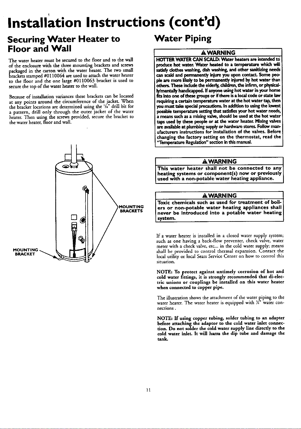
The water heater must be secured to the floor and to the wall
of the enclosure with the three mounting brackets and screws
packaged in the carton with the water beater. The two small
brackets stamped #0110064 areused to attach the water heater
to the floor and the one large #0110063 bracket is used to
secure the top of the water heater to the wall.
Because of installation variances these brackets can be located
at any points around the circumference of the jacket. When
the bracketlocations are determined using the %"drill bit for
a pattern, drill only through the outer jacket of the water
heater. Then using the screws provided, secure the bracket to
the water heater, floor and wall.
Water Piping
AWARNING
HOTTERWATERCAN SCALD:.Water heatersareintendedto
_roducehotwater.Water heatedto a temperaturewhichwill
sa_fy clotheswashing,dishwashing,andothersanitizingneeds
canscaldandpermanentlyinjureyouuponcontact.Somepeo-
deare moreh_qyto bepermanentlyinjuredbyhotwaterthan
•ber_ Theseincludetheelderly,children,theinfirm,or physicab
lylmeotanyhandicapped.Ifanyoneusinghotwaterinyourhome
EtsintooneofthesegroupsorIf thereisalocalcodeorstatelaw
requiringacertaintemperaturewater atthe hotwater talgthen
¢u musttakespecialprecau_ng Inadditionto usingthe lowest
mssibletemperatu_ suttingthat satisfiesyourhotwaterneeds,
meanssuchasa m_mg valve,shouldbeusedat thehotwater
tapsusedby thesepeopleor at thewater heater.Mixingvalves
areavailableatplumbingsupplyor hardwarestore_Followman-
ufacturersinstructionsfor installationof the valves.Before
changingthe factory setting on the thermostat, read the
'fl'emperatureRegulation"sectioninthis manual.
BRACKET
MOUNTING
BRACKETS
AWARNING
This water heater shall not be connected to any
heating, systems or component(s) now or previously
used with a non-potable water heating appliance. I
A WARNING I
Toxic chemicals such as used for treatment of boil-
ers or non-potable water heating appliances shall I
never be introduced into a potable water heating I
system. I
If a water heater is installed in a closed water supply system;
such as one having a back-flow preventer, check valve, water
meter with a check valve, etc.., in the cold water supply; means
shall be provided to control thermat expansion. Contact the
local utility or local Sears Service Center on how to control this
situation.
NOTE: To protect against untimely corrosion of hot and
cold water fittings, it is strongly recommended that di-elec-
tric unions or couplings be installed on this water heater
when connected to copper pipe.
The illustration shows the attachment of the water piping to the
water heater. The water heater is equipped with 3A"water con-
nections.
NOTE: If using copper tubing, solder tubing to an adapter
before attaching the adaptor to the cold water inlet connec-
tion. Do not solder the cold water supply line directly to the
cold water inlet. It will harm the dip tube and damage the
tank.
11
Installation Instructions (cont'd)
Water Piping (cont'd)
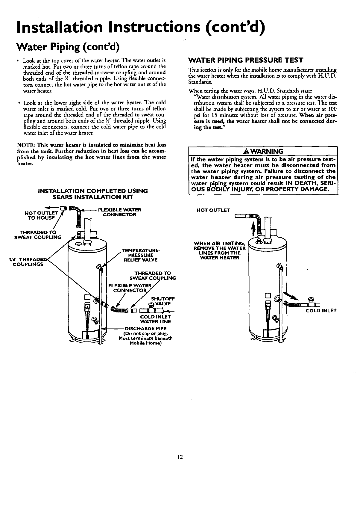
• Look at the top cover of the water heater. The water outlet is
marked hot. Put two or three turns of teflon tape around the
threaded end of the threaded-to-sweat coupling and around
both ends of the ¾ threaded nipple. Using flexible connec-
tors, connect the hot water pipe to the hot water outlet of the
water heater.
• Look at the lower right side of the water heater. The cold
water inlet is markedcold. Put two or three turns of teflon
tape around the threaded end of the, threaded-to-sweat cou-
plingand around both ends ofthe_ threaded nipple. Using
flexible connectors, connect the cold water pipe to the cold
water inlet of the water heater.
WATER PIPING PRESSURE TEST
This _ection is only for the mobile home manufacturer installing
the water heater when the installation is to comply with H.U.D.
Standards.
When testing the water ways, H.U.D. Standards state:
"Water distribution system. All water piping in the water dis-
tribution system shall be subjected to a pressure test. The test
shall be made by subjecting the system to air or water at 100
psi for 15 minutes without loss of pressure. When air pres-
sure is used, the water heater shall not be connected dur-
ing the test."
NOTE: This water heater is insulated to minimize heat loss
from the tank. Further reductipn in heat loss can be accom-
[lished by insulating the hot water lines from the water
eate_
INSTALLATION COMPLETED USING
SEARS INSTALLATION KIT
AWARNING
If the water piping system is to be air pressure test-
ed, the water heater must be disconnected from
the water piping system. Failure to disconnect the
water heater during air pressure testing of the
water piping system could result IN DEATH, SERI-
OUS BODILY INJURY, OR PROPERTY DAMAGE.
HOT OUTLET
HO+OU !
TO HOUSE
CONNECTOR
THREADED TO
SWEAT COUPLING
314"
COUPLINGS
PRESSURE
RELIEF VALVE
THREADED TO
SWEAT COUPLING
SHUTOFF
VALVE
COLD INLET
WATER LINE
(Do not cap or plug.
Must terminate beneath
Mobile Home)
WHEN AIR TESTING,
REMOVE THE WATER
LINES FROM THE
WATER HEATER
[]
COLD INLET
12
installation Instructions (cont'd)
Temperature-Pressure Relief Valve
_WARNING
At the time of manufacturethis water heater wasprovided
witha combinationtemperature-pressuresreliefvalvecertified
by a nationallyrecbgnized testinglaboratory that maintains
periodicinspectionof productionof listedequipmentor mate-
rials, as meeting the requirements for Relief Valves and
AutomaticGasShutoffDevicesfor Hot Water SupplySystems,
andthe latesteditionof ANSI Z21.22 and the coderequire-
mentsof ASME.If replaced,the valvemustmeet the require-
ments oflocalcodes,butnot lessthan a combinationtempera-
turnand pressurerelief valvecertifiedasmeetingthe require-
mentsfor ReliefValvesandAutomaticGasShutoffDevicesfor
Hot Water SupplySystems,ANSI Z2h22 by a nationallyrecog-
nizedtestinglaboratorythat maintainsperiodicinspectionof
productionoflistedequipmentor material_
The valvemust bemarkedwith a maximumset pressurenot
to exceedthe marked hydrostaticworking pressureof the
water heater(150 IbsJsq.in.)and a dischargecapacitynot less
thanthe water heaterinputrate asshownonthe modelrating
plate. (Electricheaters- watts dividedby 1000x 3415 equal
BTU/Hr.rate.)
Yourlocaljurisdictionalauthority,whilemandatingthe useofa
temperature-pressurerelief valvecomplyingwith ANSI Z21.22
and ASME,mayrequire a valvemodeldifferentfrom the one
furnishedwiththewaterheater.
Compliancewith suchlocalrequirementsmustbe satisfiedby
the installeror enduserofthe waterheaterwith a locallypre-
scribedtemperature-pressurereliefvalveinstalledin thedesig-
nated openingin the water heaterin placeofthe factory fur-
nishedvalve.
Forsafeoperationof thewaterheater,the reliefvalvemustnot
be removedfrom it'sdesignat_clopeningorplugged.
Thetemperature-pressurereliefvalvemustbe installeddirectly
intothefittingofthewater heaterdesignatedfor thereliefvalve.
Positionthe valvedownwardandprovidetubingsothatanydis-
chargewill exit onlywithin 6 inchesabove,or at anydistance
belowthe structuralfloor.Re certainthat no contactismade
withanyliveelectricalpart.The dischargeopeningmustnot be
blockedor reducedin sizeunder anycircumstances.Excessive
length, over30 feet,or useofmorethanfourelbowscancause
restriction andreducethedischargecapacityofthevalve.
No valveor otherobstructionisto beplacedbetweentherelief
valveandthetank, Do not connecttubingdirectlyto discharge
drainunlessa6"air gapisprovided.Topreventbodilyinjury,haz-
ardto life,or propertydamage,thereliefvalvemust beallowed
to dischargewaterinquantitiesshouldcircumstancesdemand.If
the dischargepipeisnotconnectedto a drainor othersuitable
means,the water flowmaycausepropertydamage.
The DischargePipe:
• Mustnot be smallerin sizethan the outlet pipesizeofthe
valve,or haveanyreducingcouplingsor otherrestrictions.
• Mustnot bepluggedor blocked.
• Mustbeofmateriallistedfor hotwater distribution.
• Mustbe installedsoas to allowcompletedrainageof both
the temperature-pressurerelief valve, and the discharge
pipe.
• Mustterminateat anadequatedraln.
• Mustnothaveanyvalvebetweenthereliefvalveandtank.
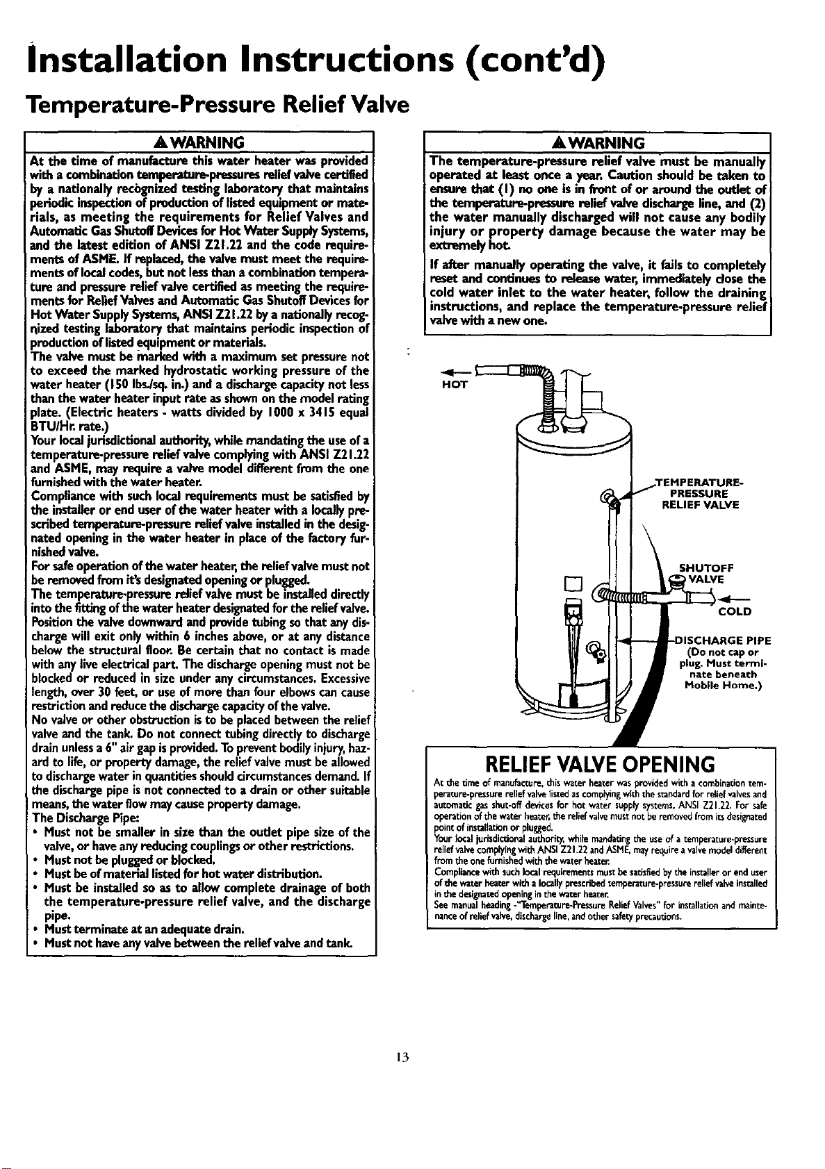
AWARNING
The temperature-pressure relief valve-must be manually
operated at least oncea year. Caution shouldbe taken to
ensurethat (I) no one isin front of or aroundthe outlet of
the temperature-pressure relief valvedischargeline, and(2)
the water manually dischargedwill not causeany bodily
injury or property damage because the water may be
extremelyhot.
If after manuallyoperatingthe valve,it failsto completely
resetand continuesto releasewater, immediatelyclosethe
cold water inlet to the water heater, follow the draining
instructions, and replacethe temperature-pressure relief
valvewith anewone.
HOT
PRESSURE
RELIEF VALVE
SHUTOFF
VALVE
COLD
(Do not cap or
plug. Must termi-
nate beneath
Mobile Home.)
RELIEFVALVEOPENING
At thetime of manufacture,thiswater heaterwasprovidedwithacombinationtem-
perature-pressurereliefvalvelistedascomplyingwiththestandardfor reliefvalvesand
automaticgasshut-offdevicesfor hotwatersupplysystems,ANSIZ21.22_Forsafe
operationof thewaterheater,thereliefvalvemustnotberemovedfromitsdesignated
pointofinstallationorplugged,
Your_ocaljurisdictionalauthority,whilemandatingthe useof a temperature-pressure
reliefvalvecomplyingwith ArqSIZ2L22andASME.mayrec_uireavalvemodeldifferent
fromtheonefurnishedwiththewaterheater
Compliancewithsuchlocalrequirementsmustbesatisfiedbytheinstalleror enduser
ofthewaterheaterwithalocallyprescribedcemperature-pressurereliefvalveinstalled
inthe designatedopeninginthewaterheater.
Seemanualheading-"Temperature-PressureReliefValves"for ins_llationandmainte-
nanceofreliefvalve,dischargeline.andothersafetyprecautions.
13
Installation Instructions (cont'd)
Filling the Water Heater
CAUTION
Never usethis water heater unlessit iscompletelyfilled
water.Toprevontdamageto thetank,the tankmustbefilled_
with water..Water must flow from the hot water faucet
beforetummg ON gastothe water heater.
To fill the water heater with water:
• Close the water heater drain valve by turning the handle to
the right (clockwise). The drain valve is on the lower front of
the water heater.
Open the cold water supply valve to the water heater.
NOTE: The cold water supply valve must be left open
when the water heater is in use.
To insure complete' filling of the tank, allow air to exit by
opening "the nearest hot water faucet. Allow water to run
until a constant flow is obtained. This will let air out of the
water heater and the piping.
Check all new water piping for leaks. Repair as needed.
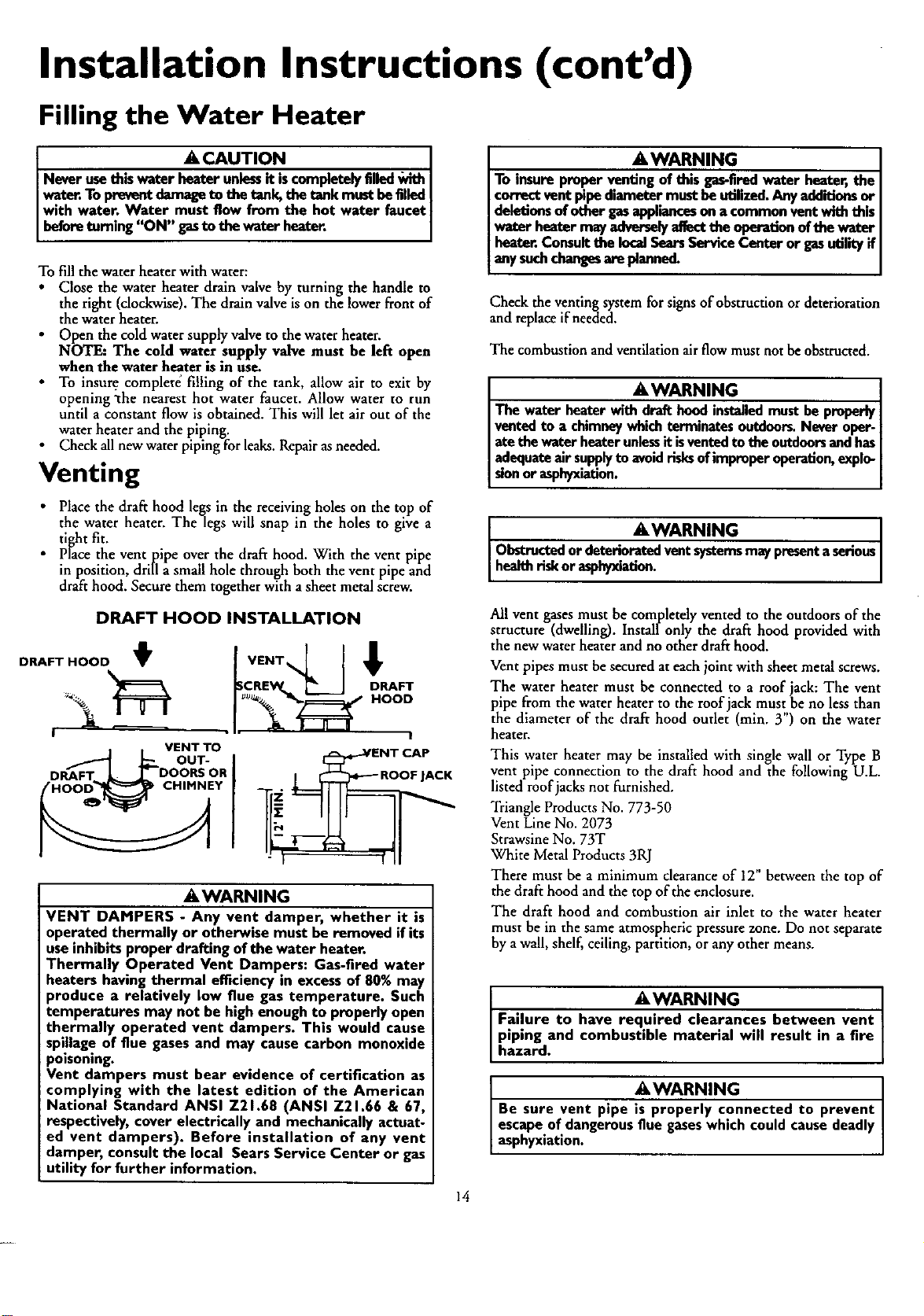
Venting
Place the draft hood legs in the receiving holes on the top of
the water heater. The legs will snap in the holes to give a
tight fit.
Place the vent pipe over the draft hood. With the vent pipe
in position, drill a small hole through both the vent pipe and
draft hood. Secure them together with a sheet metal screw.
DRAFT HOOD INSTALLATION
DRAFT HOOD
!
VENT TO
OUT-
DRAFT • DOORS OR
HOOD CHIMNEY
_SCREW_ l_ I DRAFT
_E,WARNING
VENT DAMPERS - Any vent damper, whether it is
operated thermally or otherwise must be removed if its
useinhibits proper drafting of the water heater.
Thermally Operated Vent Dampers: Gas-fired water
heaters having thermal etficiency in excessof 80% may
_roduce a relatively low flue gas temperature. Such
temperatures may not be high enoughto properly open
thermally operated vent dampers. This would cause
spillage of flue gasesand may cause carbon monoxide
poisoning.
Vent dampers must bear evidence of certification as
complying with the latest edition of the American
National Standard ANSI Z21.68 (ANSI Z21.66 & 67,
respectively, cover electrically and mechanicallyactuat-
ed vent dampers). Before installation of any vent
damper, consult the local Sears Service Center or gas
utility for further information.
AWARNING
To insure proper venting of this gas-fired water heater, the
correct vent pipe diameter must be utilized. Any additions or
deletions of other gasappliances on a common vent with this
water heater may adversely affect the operation of the water
heater. Consult the local SearsService Center or gasutility if
any suchchangesaro planned.
Check the venting system for signs of obstruction or deterioration
and replace if needed.
The combustion and ventilation air flow must not be obstructed.
AWARNING 1
The water heater with draft hood inst_led must be properly
vented to a chimney which terminates outdoors. Never oper-
ate the water heater unlessit isvented to the outdoorsand has/
adequate air supplyto avoidrisksof improper operation, explo-
sionorasphyxiation. ]
AWARNING
Obstructedor deterioratedventsystemsmaypresentaserious
healthrisk orasphyxiation.
All vent gases must be completely vented to the outdoors of the
structure (dwelling). Installonly the draft hood provided with
the new water heater and no other draft hood.
Vent pipes must be secured at each joint with sheet metal screws.
The water heater must be connected to a roof jack: The vent
pipe from the water heater to the roof jack must, be no less than
the diameter of the draft hood outlet (min. 3 ) on the water
heater.
This water heater may be installed with single wall or Type B
vent pipe connection to the draft hood and the following U.L.
listed ruofjacks not furnished.
Triangle Products No. 773-50
Vent Line No. 2073
Strawsine No. 73T
White Metal Products 3RJ
There must be a minimum clearance of 12" between the top of
the draft hood and the top of the enclosure.
The draft hood and combustion air inlet to the water heater
must be in the same atmospheric pressure zone. Do not separate
by a wall, shelf, ceiling, partition, or any other means.
AWARNING I
Failure to have required clearances between vent
piping and combustible material will result in a fire
hazard.
AWARNING I
Be sure vent pipe is properly connected to prevent I
escapeof dangerousflue gaseswhich could causedeadly
asphyxiation.
14
Installation Instructions (cont'd)
Venting (cont'd)
&WARNING
Chemical vapor corrosion of the flue and vent system
may occur if air for combustion contains certain chemical
vapors. Spray can propellants, cleaning solvents, refrigera-
tor and air conditioner refrigerants, swimming pool
chemicals, calcium and sodium chloride, waxes, bleach
and process chemicals are typical compounds which are
potentially corrosive.
Gas Piping
a, WARNING
Make sure the gas supplied is the same typ_elisted on the
model rating plate. The inlet gas pressure must not exceed
14 inches water column '/2pound per square inch (3.5kPa).
The minimum inlet gas pressure listed on the model rating
)late isfor the purpose of input adjustment.
AWARNING
If the gasconUol valve issubjected to pressures exceeding
pound per square inch (3.5kPa), the damage to the gas con-
tro valvecoudresut nalireorexposonfrom eakngg_
AWARNING
If the main gas line shutoff ser_ng all gas appliances is used,
also turn "OFF" the gasat each appliance. Leave all gasappli-
ancasshut off until the water heater installation iscomplete.
t AWARNING t
The appliance and its,._ must be leaktested
beforeplacingthe applianceinoperation.
AWARNING
• The appliance and its individualshutoff valve must be discon-
nected from the gassupplypiping systemduring any pressure
testing of the gas system at test pressures in excess of %
poundper square inch (3.SkPa).
• The appliance must be isolated from the gassupplypiping sys-
tem by closingits individualmanual shutoff valve during any
pressure testing of the gassupplypiping system at test pres-
suresequal or lessthan ½pound per square inch (3.5kPa).
AWARNING J
Use pipe joint compound or teflon tape marked as being
resistant to the action of petro eum [Propane (L.R)] gases.
A gas line of sufficient size must be run to the water heater.
Consult the latest edition of National Fuel Gas Code ANSI
Z223.1, also referred to as NFPA54 and the gas company concern-
ing pipe size.
There must be:
• A readily accessible manual shut offvalve in the gas supply line
serving the water heater, and
• A drip leg (sediment trap) ahead of the gas control valve to help
prevent dirt and foreign materials from entering the gas control
Valve.
• A flexible gas connector or a ground joint union between the
shutoffvalve and control valve to permit servicing of the unit.
Be sure to check all the gas piping for leaks before lighting the
water heater. Use a soapy water solution, not a match or open
flame. Rinse offsoapy solution and wipe dry.
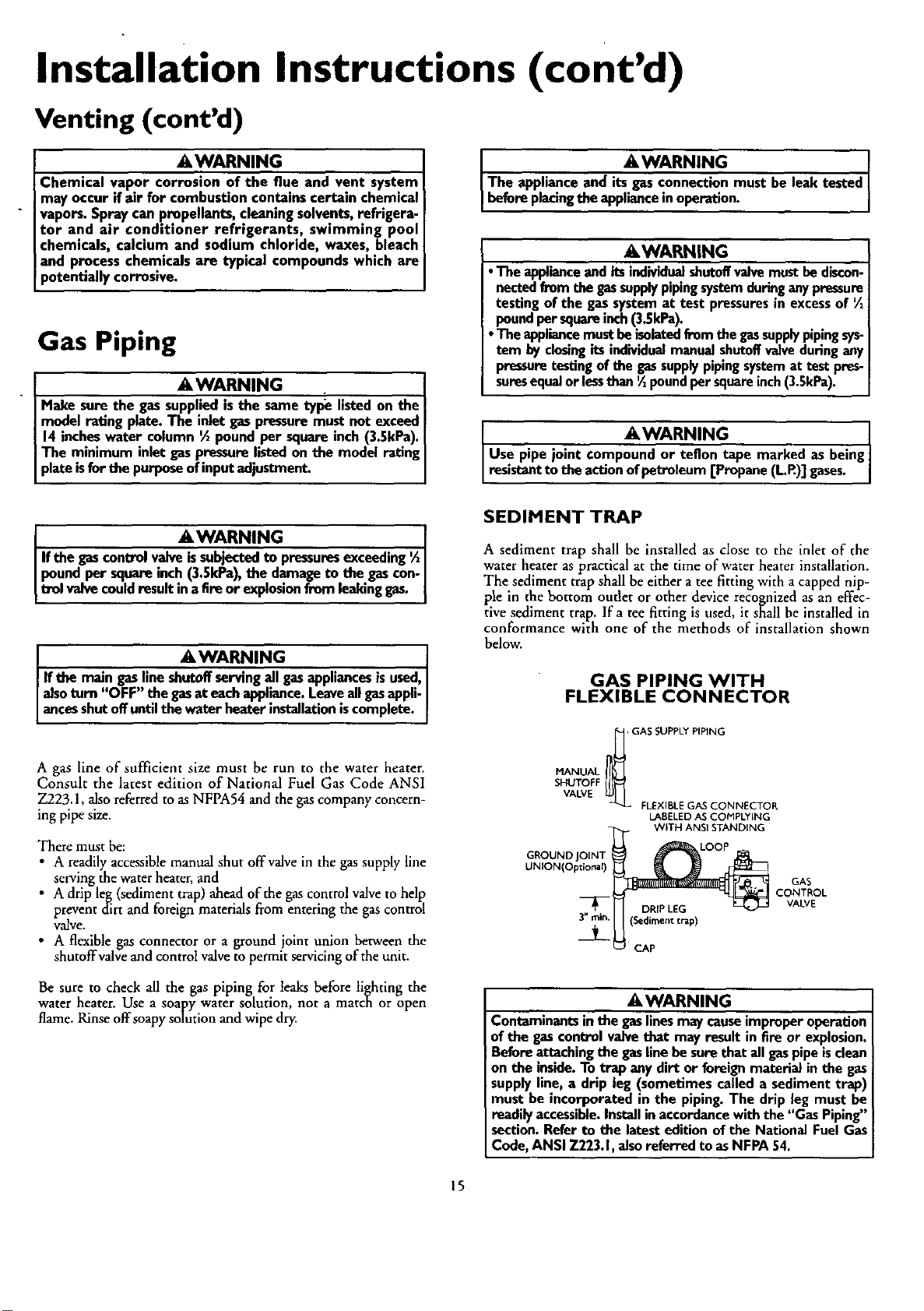
SEDIMENT TRAP
A sediment trap shall be installed as dose to the inlet of the
water heater as practical at the time of water heater installation.
The sediment trap shall be either a tee fitting with a capped nip-
pie in the bottom outlet or other device recognized as an effec-
tive sediment trap. Ifa tee fitting is used, it shall be installed in
conformance with one of the methods of installation shown
below.
GAS PIPING WITH
FLEXIBLE CONNECTOR
_/_, GASSUPPLYPIPING
HANUAL
SHUTOFF
VALVE
FLEXIBLEGAS CONNECTOR
LABELEDAS CONPLYING
WITH ANSI STANDING
GROUND
UNION(Optional)
DRIP LEG
3" rain. (Sedimenttrap)
GAS
CONTROL
VALVE
CAP
AWARNING
Contaminants in the gas lines may causeimproper operation
of the gas control valve that may result in fire or explosion.
Before attaching the gas line be sure that all gas pipe isclean
on the inside. To trap any dirt or foreign material in the gas
supply line, a drip leg (sometimes called a sediment trap)
must be incorporated in the piping. The drip leg must be
readily accessible.Install in accordance with the "Gas Piping"
section. Refer to the latest edition of the National Fuel Gas
Code, ANSI 7-223.1, also referred to as NFPA 54.
15
Installation Instructions (cont'd)
"Fuel" Conversion Instruc-
tions From Natural Gas To
Propane (L.P.) Gas
A, WARNING
This water heater has been factory equipped to operate
with the type gasindicatedin the "EQUIPPED FOR" area
of the model rating plate located near the gas control
valve. The indicated gas may be either Natural or
Propane (L.R). By followingthe conversioninstructionsin
this manualor the instructionsnear the gascontrolvalve,
the water heater must be converted if it is to be used
with the opposite gas. DO NOT USE THIS WATER
HEATER WITH ANY GAS OTHER THAN THE ONE
LISTED ON THE MODEL RATING PLATE. Failureto use
the correct gascan causeproblems which can result in
DEATH, SERIOUS BODILY INJURY, OR PROPERTY
DAMAGE. If you have any questions or doubts consult
yourgassupplieror gascompany.
Read and follow detailed conversion instructions located on the
water heater and also in this manual in their entirety beforestarting
the conversion.
Conversion kit with necessary parts are in a bag attached to the
drain valve.
Step 1.
Step 2.
Step 3.
Turn gas control knob "A"to _PILOT'. Depress andturn
_OFF". (See Figure 1, page 17).
Remove outer and inner access doors from water beater.
Remove burner assembly from water heater and contml by
loosening 3A"nut "H" holding burner assembly to control
(See Figure 2, page 17). Loosen pilot tube nut _J" and
thermocouple nut "K" at control.
Step 4. Remove screws "D" disengaging manifold from burner.
(See Figure 3, page 17)
Step 5. Remove orifice "E" (See Figure 3, page 17) using %"
wrench. Install orifice marked "L.P." found in the ba.g
into manifold. Tighten securely. Secure burner to mani-
fold with screws "D'.
Step 6. Loosen pilot tube nut "F" (See Figure 4, page 17). Re-
move orifice "G" and replace with blue colored orifice
found in bag. Reinstall nut "F" and tighten securely.
Step 7. Makesure allconnections aretightened securely,and rein-
stall burner assemblyinto waterhearer. Position end ofthe
manifold inside bracket as shown in Figure 3 on page 17.
Reinstall manifold into control andtighten _" nut (_H')
securely.Recheckto see that end of manifold isstill inside
bracket as shown in Figure3 on page 17. Reinstall pilot
tubing and thermocouple into control. (See Figure 2,
page 17)
Step 8. Place screwdriver in slot "B". (SeeFigt2re1, page 17). De-
press and turn counter-clockwise (_""q to stop. Con-
trol screw must be in "IN" position for propane (L.P.)gas
and in "OUT" position for natural gas. STOP! Readlabel
"For Your Safety" located on your water heater.
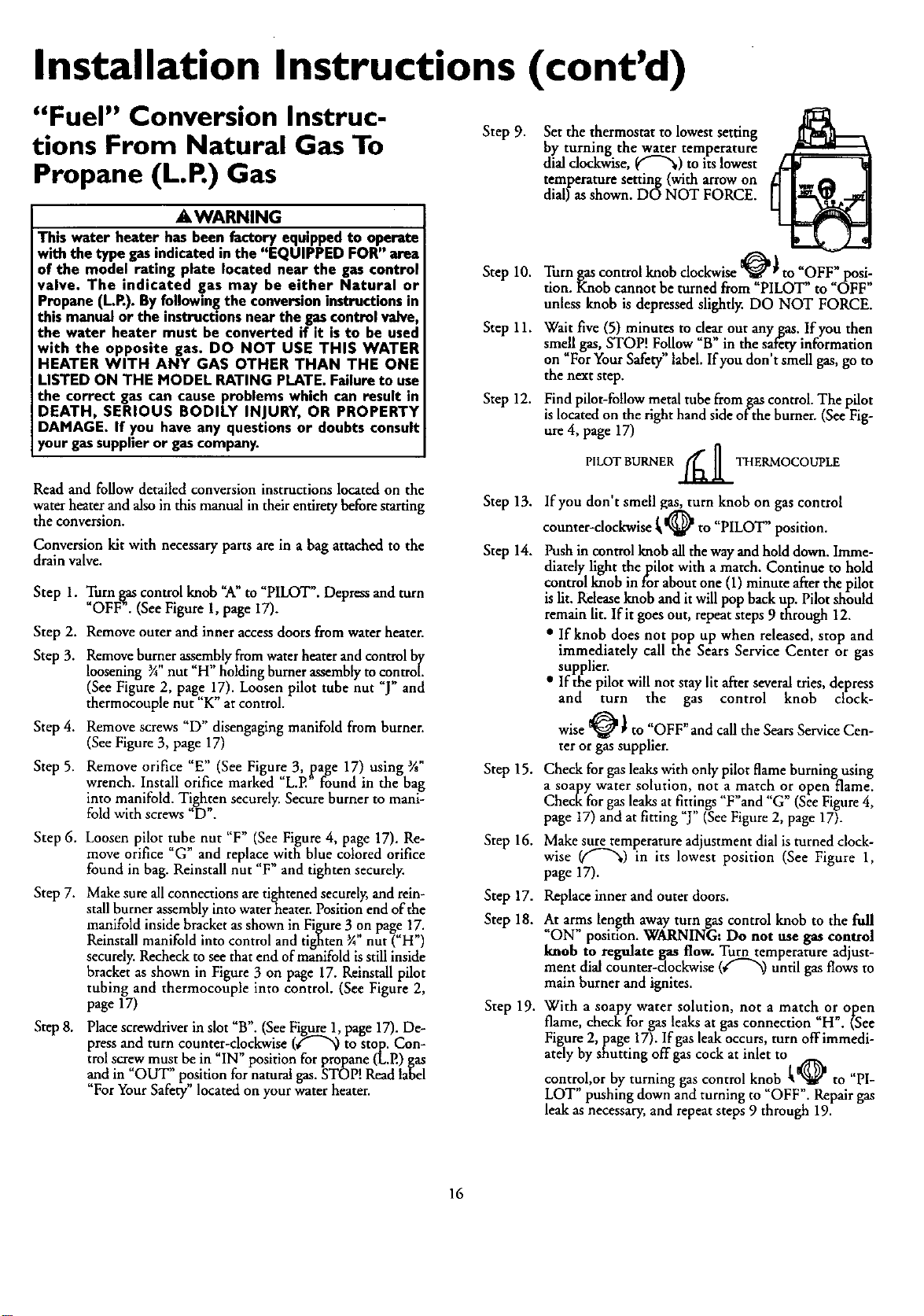
Step 9.
Step 10.
Step 11.
Step 12.
Step 13.
Step 14.
Step 15.
Step 16.
Step 17.
Step 18.
Step 19.
Set the thermostat to lowest setting
by turning the water temperature
dial dockwise, _"-"_) to itslowest
temperature setting (with arrowon
dial) as shown. DO NOT FORCE.
Turn gas control knob clockwise _ _ to _OFF" posi,-'
tion. Knob cannot be turned from PILOT" to OFF
unless knob is depressed slightly. DO NOT FORCE.
Wait five (5) minutes to c!e-_rout any gas. If you then
smell gas, STOP! Follow B in the saf&y information
on _For Your Safety" label. Ifyou don't smell gas, go to
the next step.
Find pilot-follow metal tube from gas control. The pilot
is located on the right hand side of the burner. (See Fig-
ure 4, page 17)
t-t
PILOTBURNER/_]] THERMOCOUPLE
If you don't smell gas, turn knob on gas control
counter-clockwise [ _ to "PILOT" position.
Push in control knob all the way andhold down. Imme-
diately light thepilot with a match. Continue to hold
control knob in for about one (1) minute afterthe pilot
is lit. Releaseknob and it will pop back up. Pilot should
remain lit. If it goes out, repeat steps 9 through 12.
• If knob does not pop up when released, stop and
immediately call the Sears Service Center or gas
supplier.
• If the pilot will not stay lit afterseveraltries, depress
and turn the gas control knob clock-
wise _ ) to "OFF" and call the Sears Service Can-
ter or gas supplier.
Check for gas leakswith only pilot flame burning using
a soapy water solution, not a match or open flame.
Check for gas leaks atfittings "F"and "G" (See Figure4,
page 17) and at fitting "J" (See Figure2, page 17).
Make sure temperature adjustment dial is turned clock-
wise (("-_) in its lowest position (See Figure 1,
page 17).
Replaceinner andouter doors.
At arms length away turn gas control knob to the full
"ON" position. WARNING: Do not use gas control
knob to regulate gas flow. Turn temperature adjust-
ment dial counter-clockwise (_"_) until gas flows to
main burner and ignites.
With a soapy water solution, not a match or open
flame, check for gas leaks at gas connection _H". (See
Figure 2, page 17). If gas leak occurs, turn offimmedi-
ately by shutting offgas cock at inlet tof_ ,,
control,or by turning gas control knob • _it_' to PI-
LOT" pushing down and turning to _OFF". Repair gas
leak as necessary, and repeat steps 9 through 19.
16
Installation Instructions (cont'd)
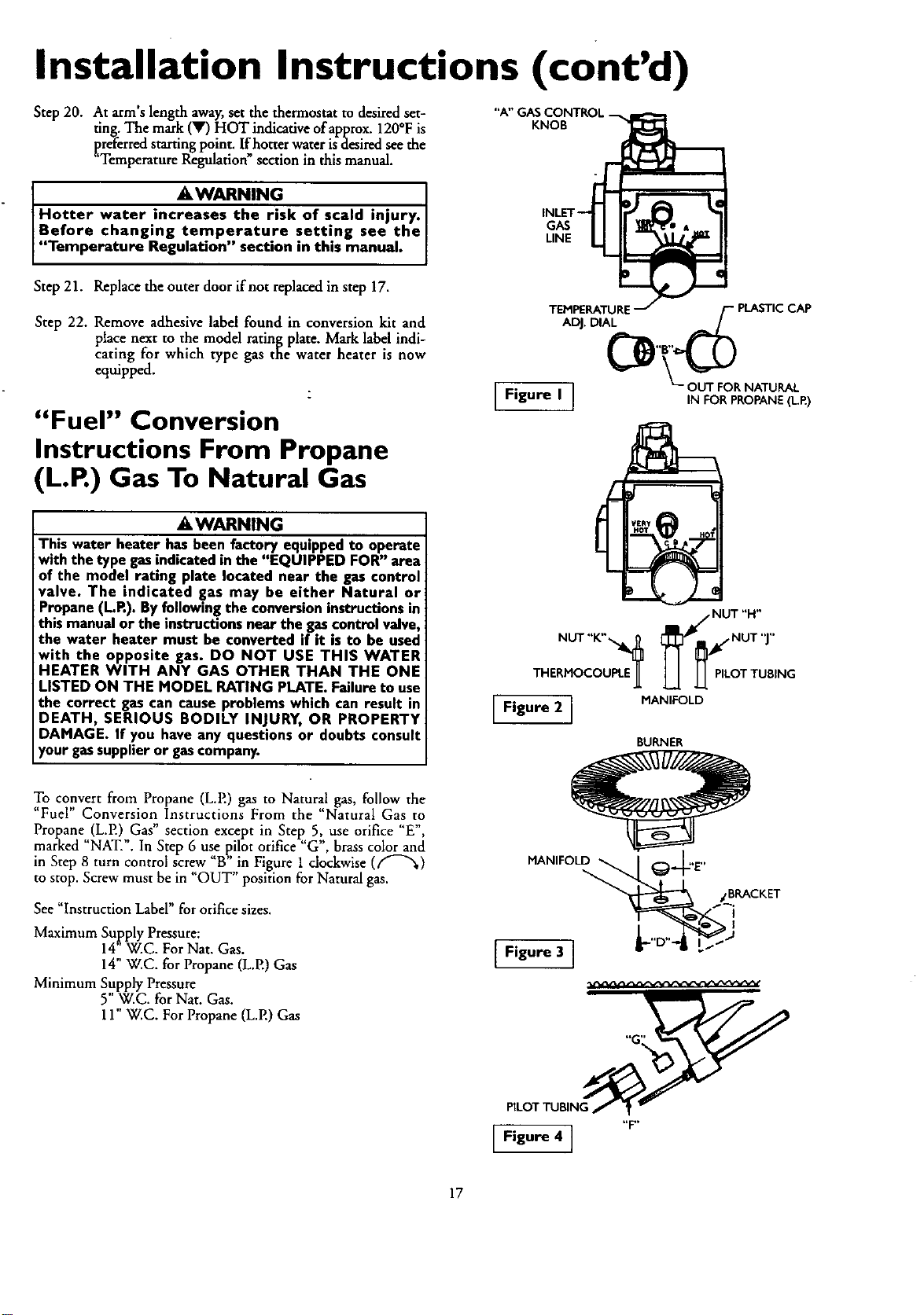
Step 20. At arm's length away,set the thermostat to desired set-
ting. The mark (V) HOT indicative of approx.120°F is
preferred starting point. If hotter water isdesired see the
"Temperature Regulation"section in this manual.
"A"(
KNOB
_WARNING. I
Hotter water increases the rtsk of scald injury. I
Before changing temperature setting see the
"Temperature Regu ation" section n th s manua.
GAS
LINE
Step 21. Replace the outer door if not replaced in step 17.
Step 22. Remove adhesive label found in conversion kit and
place next to the model rating plate. Mark label indi-
cating for which type gas the water heater is now
equipped.
z
"Fuel" Conversion
Instructions From Propane
(L.P.) Gas To Natural Gas
AWARNING
This water heater hasbeen factory equipped to operate
with the type gasindicatedinthe "EQUIPPED FOR" area
of the model rating plate located near the gas control
valve. The indicated gas may be either Natural or
Propane(L.R). Byfollowingthe conversioninstructionsin
this manualor the instructionsnear the gascontrol valve,
the water heater must be converted if it is to be used
with the opposite gas. DO NOT USE THIS WATER
HEATER WITH ANY GAS OTHER THAN THE ONE
LISTED ON THE MODEL RATING PLATE. Failureto use
the correct gas can cause problems which can result in
DEATH, SERIOUS BODILY INJURY, OR PROPERTY
DAMAGE. If you have any questions or doubts consult
your gassupplieror gascompany.
To convert from Propane (L.E) gas to Natural gas, follow the
"Fuel" Conversion Instructions From the "Natural Gas to
Propane (LP.) Gas" section except in Step 5, use orifice 'E",
marked "NAT.". In Step 6 use pilot orifice "G', brass color and
in Step 8 turn control screw "B" in Figure 1 clockwise (f'-_',)
to stop. Screw must be in "OUT" position for Natural gas.
See "Instruction Label" for orifice sizes.
Maximum Supply Pressure:
14"W.C. For Nat. Gas.
14" W.C. for Propane (L.P.) Gas
Minimum Supply Pressure
5"W.C. for Nat. Gas.
11" W.C. For Propane (L.P.) Gas
TEMPERATURE /-- PLASTIC CAP
ADJ. DIAL -- /
[ Figure I ] OUTFORNATURAL
IN FOR PROPANE(L.E)
THERi_qOCOUPLEJ_ LJ. J-_ PILOT TUBING
[ Figure 21 MANIFOLD
BURNER
F,2 i
[_ "F"
17
Installation Instructions (cont'd)
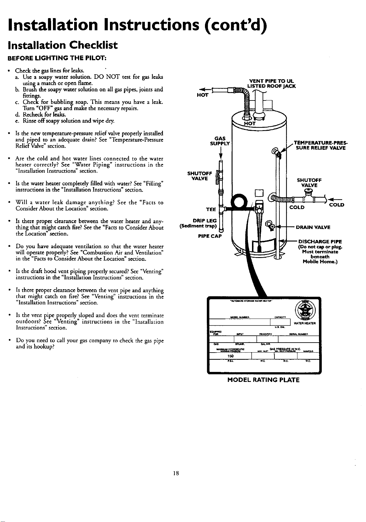
Installation Checklist
BEFORE LIGHTING THE PILOT:
• Check the gas lines for leaks.
a. Use a soapy water solution. DO NOT test for gas leaks
usinga match or open flame.
b. Brush the soapy water solution on all gas pipes, joints and
fittings.
c. Check for bubbling soap. This means you have a leak.
Turn "OFF gas andmake the necessary repairs.
d. Recheck for leaks.
e. Rinse off soapy solution and wipe dry.
• Is the new temperature-pressure reliefv_ve properly installed
and piped to an adequate drain? See Temperature-Pressure
Relief Valve section.
• Are the cold and hot water lines connected to the water
heater correctly? See "Water Piping" instructions in the
"Installation Instructions" section.
• Is the water heater completely filled with water? See "Filling"
instructions in the "Installation Instructions" section.
• Will a water leak damage anything? See the "Facts to
Consider About the Location" section.
HOT
GAS
SUPPLY
+
SHUTOFF
VALVE
TEE
HOT
VENT PIPE TO UL
LISTED ROOF JACK
.TEMPERATURE.PRES-
SURE RELIEF VALVE
SHUTOFF
VALVE
COLD COLD
• Is there proper clearance between the water heater and any-
thing that might catch fire? See the Facts to Consider About
the Location section.
• Do you have adequate ventilation so that the water heater
will operate properly? See Combustion Air and Ventilation"
in the"Facts to Consider About the Location section,
• Is the draft hood vent piping properly secured? See "Venting"
instructions in the "Installation Instructions" section.
DRIP LEG
(Sediment trap)
PIPE CAP
(Do not cap or plug,
Must terminate
beneath
Mobile Home.)
• Is there proper clearance between the vent pipe and anything
that might catch on fire? See "Venting" instructions in the
"Installation Instructions" section.
• ls the vent pipe properly sloped and does the vent terminate
outdoors? See "Venting" instructions in the "Installation
Instructions" section.
Do you need to call your gas company to check the gas pipe
and its hookup?
_ NLme_ _ACr_
m_o_A_ GAS PRESSURE _4we.
I 1 I
p_s_ we w.c we
MODEL RATING PLATE
18
Operating Instructions
Lighting
_WARNING
BEFORE LIGHTING [PROPANE (L.P.) GAS WATER
HEATERS]:Propane(LR) gasisheavierthanair.Shouldthem
bea leakin the system,the gaswill settlenear the ground.
Basements,crawlspaces,skirt_l areasunder mobilehomes
(evenwhenventilated),closetsandareasbelowgroundlevelwill
serveas pockets for the accumulation of this gas. Before
attemptingto lightor .rel.lghtthe waterheater'spilotortuming
ona nearbyelectricalhghtswitch,be absolutelysumthem isno
accumulatedgasinthearea.Searchforodorofgasbymiffing at
groundlevelin thevicinityof the appliance.Ifedor isdetected,
follow stepsindicatedat "For YourSafety"onthe coverpageof
this manualthen leavethe premise_
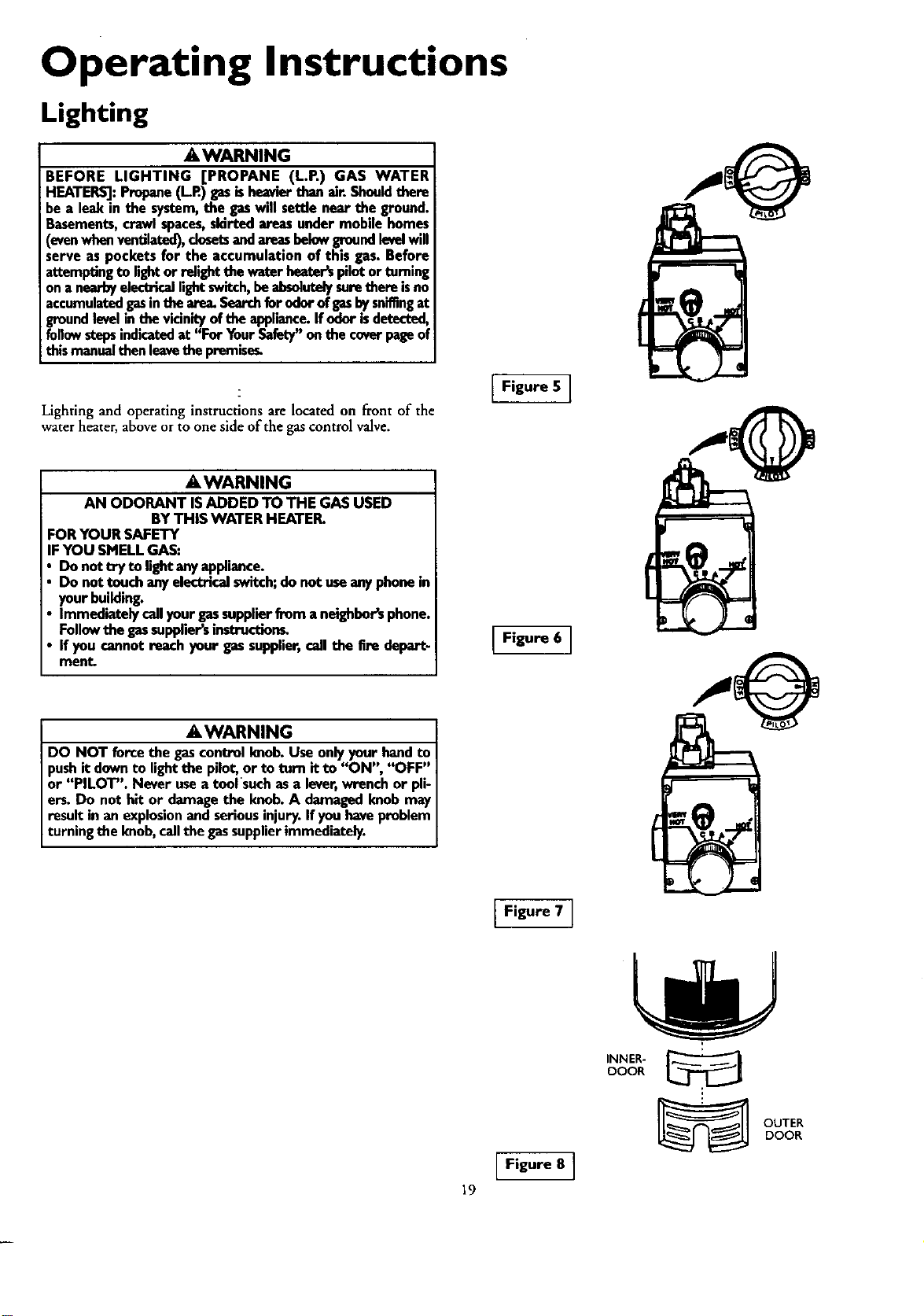
Lighting and operating instructions are located on front of the
water heater, above or to one side of the gas control valve.
Figure 5 J
AWARNING
AN ODORANT ISADDED TO THE GAS USED
BYTHIS WATER HEATER.
)RYOUR SAFETY
IFYOU SMELLGAS:
Do not try to lightanyappliance.
Do not touchanyelectricalswitch;do not useanyphonein
yourbuilding.
Immediatelycallyour gassupplierfrom a neighbor'sphone.
Followthe gassuppliersinstructions_
If you cannotreachyour gassupplier,callthe Ere depart-
ment.
Figure 6 J
AWARNING
DO NOT force the gascontrolknob.Use only your handto
pushit downto lightthe pilot,or to torn it to "ON", "OFF"
or "PILOT". Never usea tool suchasa lever,wrenchor pli-
ers. Do not hit or damagethe knob.A damagedknobmay
result in an explosionand seriousinjury.If youhaveproblem
turningthe knob,callthe gassupplierimmediately.
Figure 7 ]
|9
Figure 8 ]
INNER-
DOOR
OUTER
DOOR
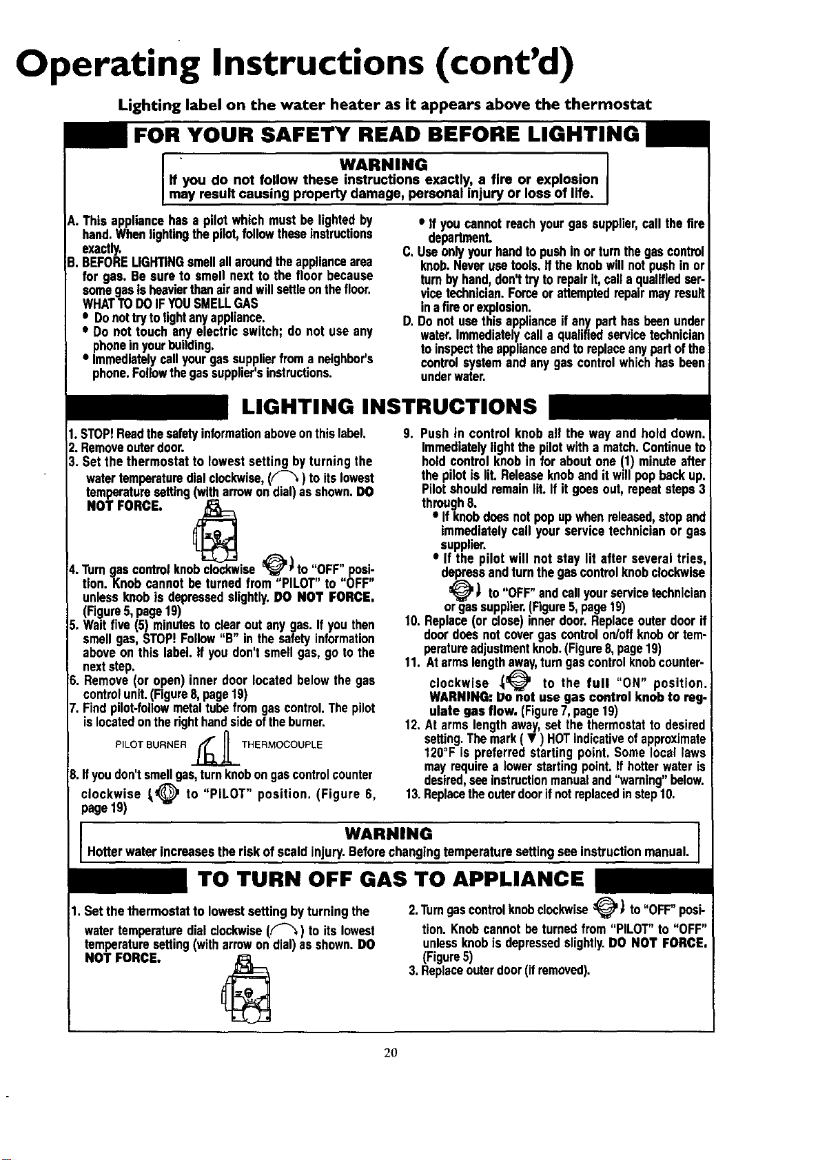
Operating Instructions (cont'd)
Lighting label on the water heater as it appears above the thermostat
FOR YOUR SAFETY READ BEFORE LIGHTING
• WARNING J
If you do not follow these instructions exactly, a fire or explosion
may result causing property damage, personal injury or loss of life.
A. Thisappliancehasa pilot whichmustbe lightedby
hand.WhenIighUngthepilot,followtheseinstructions
exactly.
B. BEFORELIGHTINGsmellallaroundtheappliancearea
for gas, Be sureto smell nextto the floor because
somegasisheavierthanair andwillsettleonthefloor.
WHATTODOIF YOUSMELLGAS
• Donottrytolight anyappliance.
• Do not touch anyelectric switch;do not useany
phoneinyourbuilding.
• Immediatelycallyourgassupplierfroma neighbor's
phone.Followthegassupplier'sinstructions.
Cl
D.
• If youcannotreachyourgassupplier,callthe fire
department.
Useonlyyourhandto pushinor turnthegascontrol
knob.Neverusetools.Ifthe knobwillnot pushin or
turnbyhand,donl tryto repair it,calla qualifiedser-
vicetechnician.Forceor attemptedrepairmayresult
inafireorexplosion.
Do not usethis applianceif anyparthasbeenunder
water.Immediatelycall a qualifiedservicetechnician
toinspecttheapplianceandto replaceanypartofthe
controlsystemandany gascontrolwhichhasbeen
underwater.
LIGHTING INSTRUCTIONS
1.STOP!Readthesafetyinformationaboveonthislabel.
2, Removeouterdoor.
3. Setthe thermostatto lowestsetting byturning the
watertemperaturedialclockwise,(f-'_) to itslowest
temperaturesetting(witharrowon dial)asshown.DO
NOT FORCE.
4.Turngascontrolknobclockwise_'* to OFF"posi-
tion.Knob cannotbe turnedfrom "PILOT" to "OFF"
unlessknobis depressedsgghtly.DO NOT FORCE.
(Figure5, page19)
Waitfive(5) minutesto clearout anygas. Ifyou then
I II ,e
smellgas,STOP.Follow B in the safetyinformation
aboveon this label If youdon'tsmell gas,go to the
nextstep.
Remove(or open)inner door locatedbelowthe gas
controlunit.(Figure8,page19)
Findpilot-followmetaltubefromgascontrol.Thepilot
islocatedontherighthandsideoftheburner.
PILOT BURNER __THERMOCOUPLE
Ifyoudon'tsmellgas,turnknobongascontrolcounter
1_@ to "PILOT" position. (Figure 6,
clockwise
page19)
9. Push in control knoball the way and hold down.
Immediatelylightthe pilotwith a match.Continueto
holdcontrolknobin for aboutone (1) minuteafter
the pilotis lit.Releaseknoband itwillpopbackup.
Pilotshouldremainlit. If it goesout,repeatsteps3
through8.
• If knobdoesnotpop upwhenreleased,stopand
immediatelycall yourservicetechnicianor gas
supplier.
• If the pilot will not stay lit after several tries,
depressandturnthegascontrolknobclockwise
_' ) to "OFF"andcallyourservicetechnician
orgassupplier.(Figure5,page19)
10.Replace(or close)innerdoor.Replaceouterdoorif
doordoesnot covergascontrolon/offknobor tem-
peratureadjustmentknob.(Figure8,page19)
11. At armslengthaway,turngascontrolknobcounter-
clockwise _)_ to the full "ON" position.
WARNING: Do not use gas control knob to reg.
ulate gas flow. (Figure7,page19)
12.At armslengthaway,set the thermostatto desired
setting.Themark( • ) HOTindicativeofapproximate
120°F is preferredstarting point. Somelocal laws
may requirea lowerstartingpoint.If hotterwateris
desired,seeinstructionmanualand"warning" below.
13.Replacetheouterdoorifnot replacedinstep10.
WARNING ]
Hotterwaterincreasestheriskof scaldinjury.Beforechangingtemperaturesettingsee instructionmanual.
TO TURN OFF GAS TO APPLIANCE
1. Set thethermostatto lowestsettingbyturning the
watertemperaturedial clockwise(Y"-'%)to itslowest
temperaturesetting(witharrowon dial)asshown.DO
NOT FORCE,
2.TurngascontrolknobclockwiseVl to"OFF"posi-
tion. Knobcannotbeturnedfrom "PILOT"to "OFF"
unlessknobisdepressedslightly.DO NOT FORCE.
(Figure5)
3,Replaceouterdoor(ifremoved).
2O
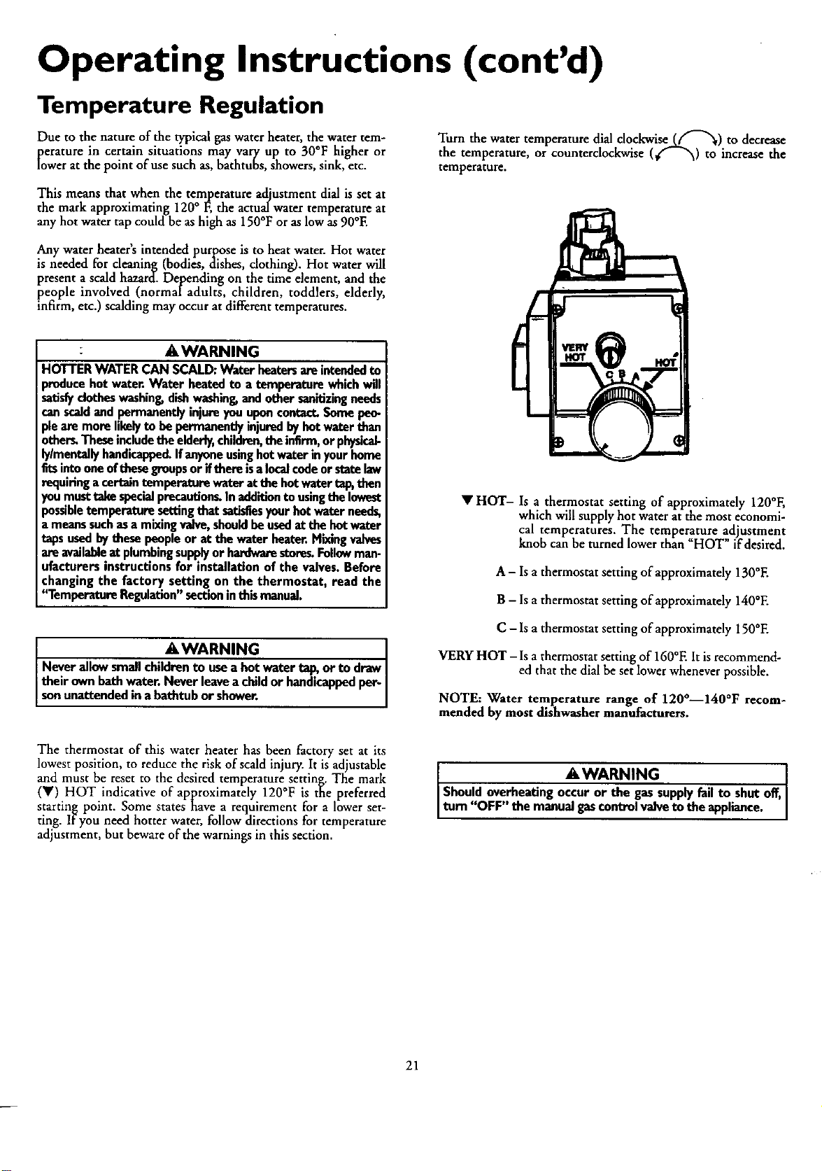
Operating Instructions (cont'd)
Temperature Regulation
Due to the nature of the typical gas water heater, the water tem-
roerature in certain situations may vary up to 30°F higher or
wer at the point of use such as, bathtubs, showers, sink, etc.
Turn the water temperature dial clockwise_.f'-_) to decrease
the temperature, or counterclockwise (€"- -'x0 to increase the
temperature.
This means that when the temperature adjustment dial is set at
the mark approximating ] 20° F, the actualwater temperature at
any hot water tap could be ashigh as 150°F or aslow as 90°E
Any water heater's intended purpose is to heat water. Hot water
is needed for cleaning (bodies, dishes, clothing). Hot water will
present a scald hazard. Depending on the time element, and the
people involved (normaladults, children, toddlers, elderly,
infirm, etc.) scalding may occur at different temperatures.
: AWARNING
HOTTERWATERCAN SCALD:Water heatersareintendedto
producehot water.Water heatedto a temperaturewhichwill
satisfydotheswashing,dishwashing,andothersanitizingneeds
canscaldandpermanentlyinjureyouuponcontact.Somepeo-
ph aremorelikelyto bepermanentlyinjuredbyhotwaterthan
others.Theseincludetheelderly,children,theinfirm,or physicab
b/mentally handicapped.Ifanyoneusinghotwaterinyourhome
fitsintooneofthesegroupsor ifthem isalocalcodeorstatelaw
requiring acertaintemperaturewaterat thehot water telhthen
roumusttakespecialpmcaution_In additionto usingthe lowest
_ossibletemperaturesettingthat satisfiesyourhotwater needs,
t meanssuchasa mixingvalve,shouldbeusedat thehotwater
tapsusedbythese peopleor at the waterheat_. Mixingvalves
areavallaldeat plumbingsupplyor hardwarestoresFollowman-
ufacturersinstructionsfor installationofthe valves.Before
changingthe factory setting on the thermostat, read the
"Temperature Regulation"sectioninthis manual.
f
• HOT- Is a thermostat setting of approximately 120°F,
which will supply hot water at the most economi-
cal temperatures. The temperature adjustment
knob can be turned lower than "HOT" if desired.
A - Is athermostat setting of approximately 130°E
B - Is athermostat setting of approximately 140°E
AWARNING I
Neverallowsmallchildrento usea hotwater telh or to drawI
their ownbathwater.Never leavea childor handicappedper-
sonunattended na bathtubor shower.
C - Is athermostat setting of approximately 150°E
VERY HOT - Is a thermostat setting of 160°E It is recommend-
ed that the dial be set lower whenever possible.
NOTE: Water temperature range of 120°--140°F recom-
mended by most dishwasher manufacturers.
The thermostat of this water heater has been factory set at its
lowest position, to reduce the risk of scald injury. It is adjustable
and must be reset to the desired temperature setting. The mark
(•) HOT indicative of approximately 120°F is the preferred
starting point. Some states have a requirement for a lower set-
ting. If you need hotter water, follow directions for temperature
adjustment, but beware of the warnings in this section.
AWARNING
Shouldoverheatingoccuror the gassupplyfail to shut off,
turn "OFF" the manualgascontrolvalveto the appliance,
21
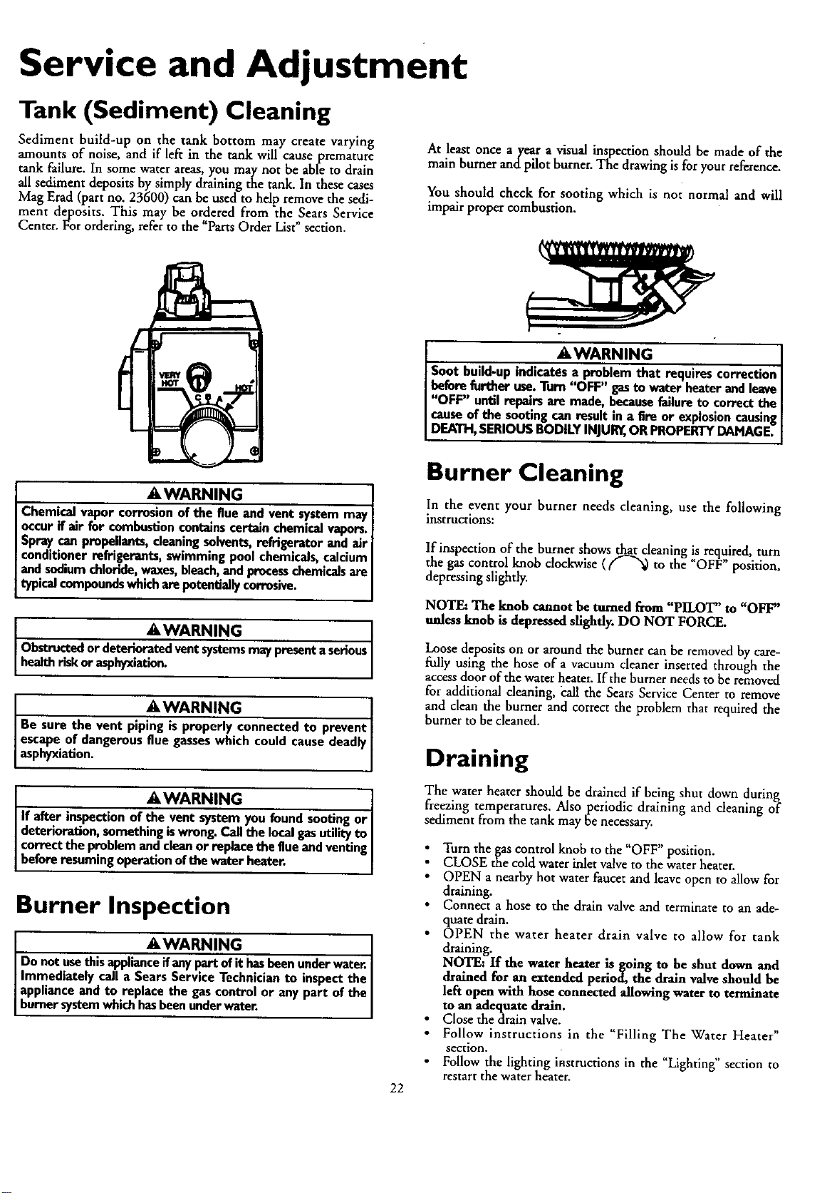
Service and Adjustment
Tank (Sediment) Cleaning
Sediment build-up on the tank bottom may create varying
amounts of noise, and if left in the tank will cause premature
tank failure. In some water areas,you may not be able to drain
all sediment deposits by simply draining the tank. In these cases
Mag Erad (part no. 23600) can be used to help remove the sedi-
ment deposits. This may be ordered from the Sears Service
Center. For ordering, refer to the "Parts Order List" section.
At least once ayear a visual inspection should be made of the
main burner and pilot burner. The drawing is for your reference.
You should check for sooting which is not normal and will
impair proper combustion.
AWARNIN_ G I
Soot build-upindlcat_S,sa problemthat requires correction
beforefurther use.Turn"OFF" gasto waterheaterandleave[
"OFF" until repairsare made, becausefailureto correctthe [
causeof the sootingcanresultin a fire or explosioncausing[
DEATH,SERIOUSBODILYINJURY,ORPROPERTYDAMAGE.]
AWARNING
Chemicalvapor corrosionof the flue and vent systemmay
occur if air for combustioncontainscert_n chemicalvapors.
Spraycanpropellants,cleaningsolvents,refrigerator and air
conditionerrefrigerants, swimmingpool chemicals,calcium
and sodiumchloride,waxes,bleach,andprocesschemicalsare
typicalcompoundswhicharepetendally corrosive.
AWARNING
Obstructedor deterioratedventsystemsmaypresentaserious
healthriskor asphyxat on.
AWARNING I
Be sure the vent pipingis properly connectedto prevent[
escapeof dangerousflue gasseswhich could causedeadly
asphyxation.
AWARNING ]
If after inspectionof the vent systemyou found sootingor I
deterioration,something iswrong.Callthe localgasutilityto |
correctthe p.roblemandcleanor replacetheflue andventing
before resuming operationofthe water heater. ]
Burner Inspection
AWARNING 1
Do notusethisapplianceifanypartof it hasbeenunderwater.|
Immediately call a SearsService Technicianto inspectthe|
applianceand to replace the gascontrolor anypart of the|
burnersystemwhichhasbeenunderwater. |
Burner Cleaning
In the event your burner needs cleaning, use the following
instructions:
If inspection of the burner shows that cleaning is required, turn
the gas control knob clockwise (_"_ to the "OFF"position,
depressing slightly.
NOTE: The knob cannot be turned from "PILOT" to "OFF"
unless knob is depressed slighfl)_ DO NOT FORCE.
Loose deposits on or around the burner can be removed by care-
fially using the hose of a vacuum cleaner inserted through the
accessdoor of the water heater• If the burner needs to be removed
for additional cleaning, call the Sears Service Center to remove
and clean the burner and correct the problem that required the
burner to be cleaned.
22
Draining
The water heater should be drained if being shut down during
freezing temperatures. Also periodic draining and cleaning of
sediment from the tank may be necessary.
Turn the gas control knob to the "OFF" position.
CLOSE the cold water inlet valveto the water heater.
• OPEN a nearby hot water faucet and leave open to allow for
draining.
• Connect a hose to the drain valve and terminate to an ade-
quate drain.
• OPEN the water heater drain valve to allow for tank
draining.
NOTE: If the water heater is going to he shut down and
drained for an extended period, the drain valve should be
left open with hose connected allowing water to terminate
to an adequate drain.
Close thedrain valve.
Follow instructions in the "Filling The Water Heater"
section.
Follow the lighting instructions in the "Lighting" section to
restart the water heater.
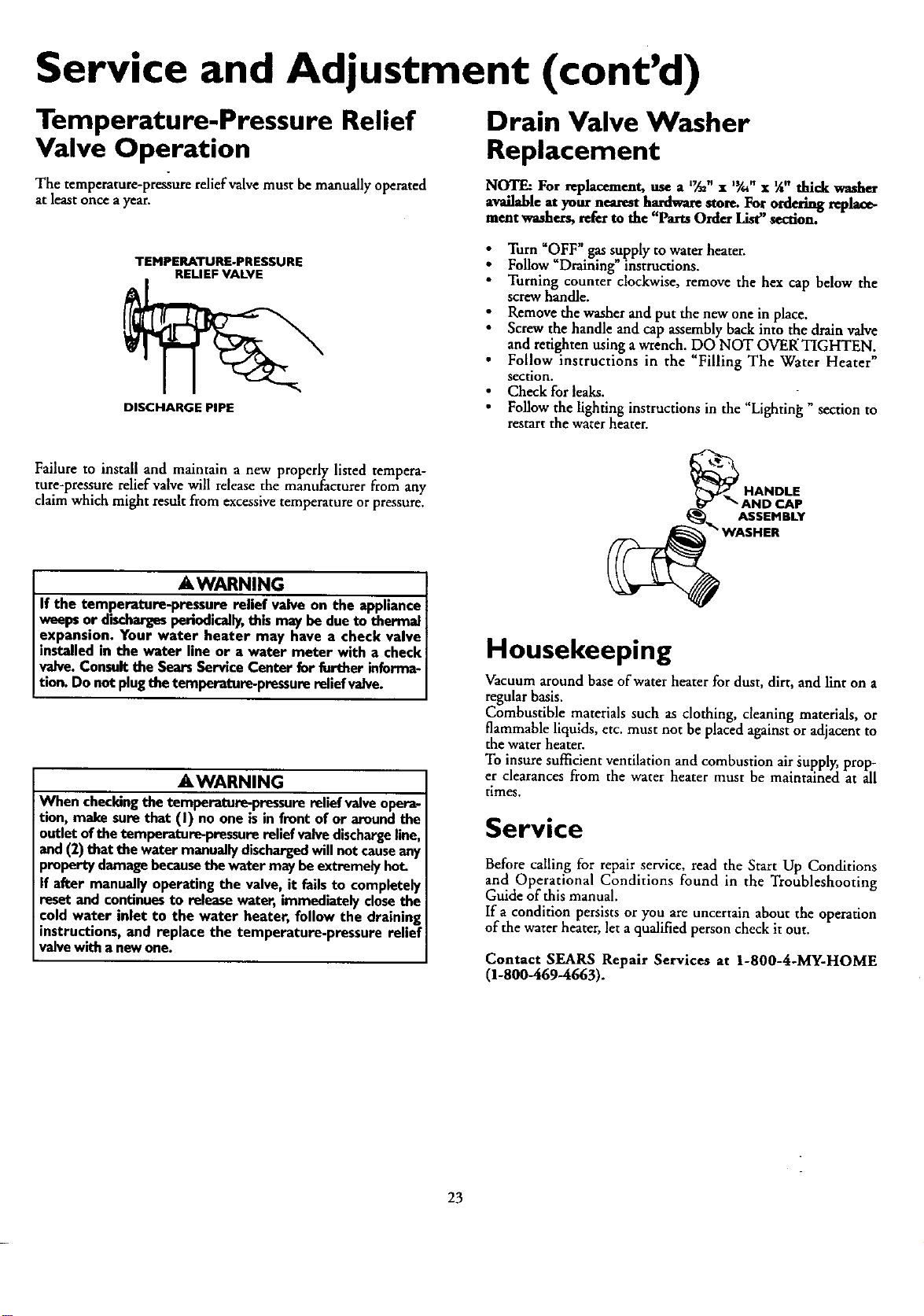
Service and Adjustment (cont'd)
Temperature-Pressure Relief
Valve Operation
The temperature-preasure relief valve must be manually operated
at least once ayear.
Drain Valve Washer
Replacement
NOTE: For replacement, use a l_t_,, x J_/." x _" thick washer
available at your nearest hardware store. For ordering replace-
ment washers, refer to the "Parts Order IAs_' section.
TEHPERATURE-PRESSURE
RELIEF VALVE
DISCHARGE PIPE
Turn _OFF" gas supply to water heater.
Follow _Draining" instructions.
Turning counter clockwise, remove the hex cap below the
screw handle.
Remove the washer and put the new one in place.
Screw the handle and cap assembly back into the drain valve
and retighten using a wrench. DO NOT OVEKTIGHTEN.
Follow instructions in the "Filling The Water Heater"
section.
Check for leaks.
Follow the lighting instructions in the "Lighting " section to
restart the water heater.
Failure to install and maintain a new properly listed tempera-
ture-pressure relief valve will release the manufacturer from any
claim which might result from excessivetemperature or pressure.
AWARNING
If the temperature-pressure relief valve on the appliance
weepsor dischargesperiodically,thismay bedueto thermal
expansion. Your water heater may have a check valve
installedin the water line or a water meter with a check
valve.Consultthe SearsServiceCenter for further informa-
tion. Do not plugthe temperature-pressurerelief valve.
AWARNING
When checkingthe temperature-pressurerelief valveopera-
tion, make surethat (I) no one isin front of or aroundthe
outletofthe temperature-pressurerelief valvedischargeline,
and(2) that the water manuallydischargedwillnot causeany
propertydamagebecausethe water maybeextremelyhot.
If after manuallyoperatingthe valve, it failsto completely
reset and continuesto releasewater, immediatelyclosethe
cold water inlet to the water heater, follow the draining
instructions,and replace the temperature-pressure relief
valvewitha newone.
ASSEMBLY
Housekeeping
Vacuum around base of water heater for dust, dirt, and lint on a
regular basis.
Combustible materials such as clothing, cleaning materials or
flammab e liquids, etc. must not be placed against or adjacent to
the water heater.
To insure sufficient ventilation and combustion air supply, prop-
er clearances from the water heater must be maintained at all
times.
Service
Before calling for repair service, read the Start Up Conditions
and Operational Conditions found in the Troubleshooting
Guide of this manual.
If a condition persists or you are uncertain about the operation
of the water heater, let a qualified person check it out.
Contact SEARS Repair Services at 1-800-4-MY-HOME
(1-800-469-4663).
23
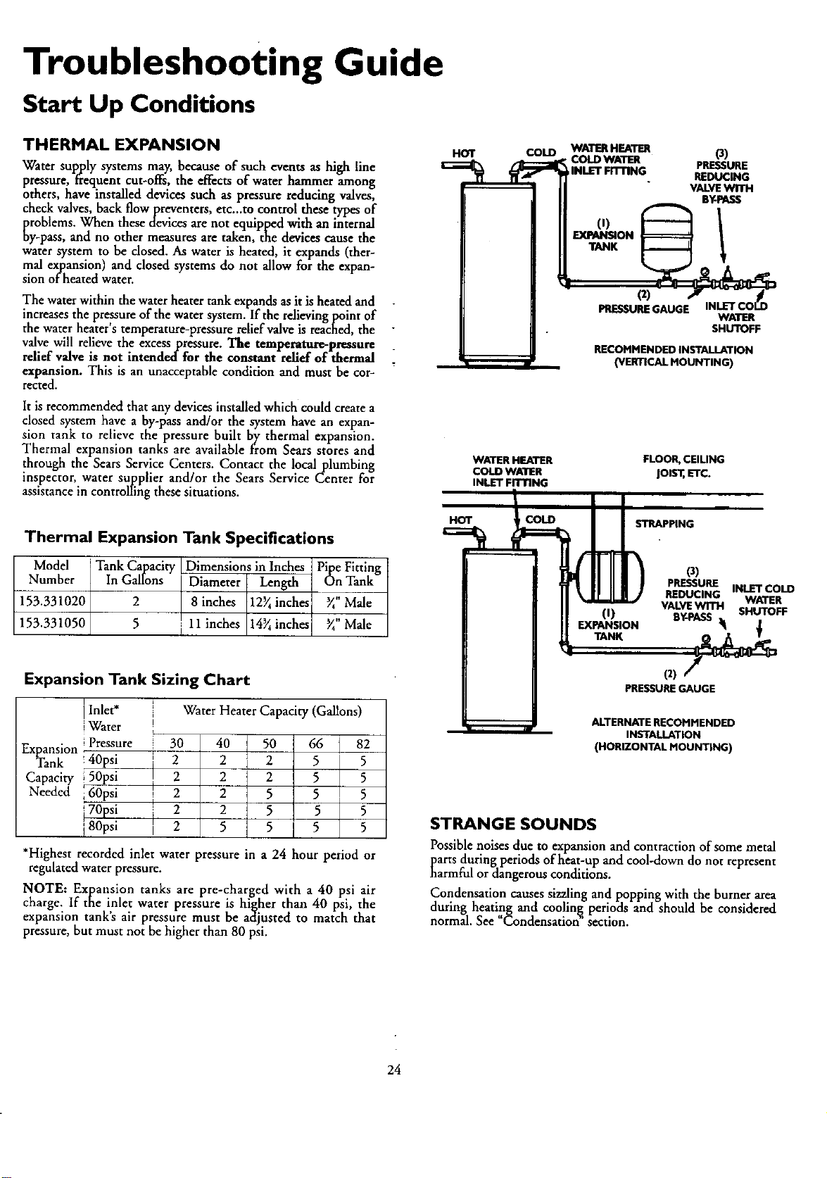
Troubleshooting Guide
Start Up Conditions
THERMAL EXPANSION
Water supply systems may, because of such events as high line
pressure, frequent cut-offs, the effects of water hammer kmong
others, have installed devices such as pressure reducing valves,
check valves, back flowpreventers, etc._to control these types of
problems. When these devices arenot equipped with an internal
by-pass, and no other measures are taken, the devices cause the
water system to be closed. As water is heated, it expands (ther-
mal expansion) and closed systems do not allow for the expan-
sion of heated water.
The water within the water heater tank expands as it is heated and
increases the pre,ssure of the water system. If the relieving point of
the water heater s temperature-pressure relief valve is reached, the
valve will relieve the excesspressure. The temperamr_pressure
relief valve is not intendedfor the constant relief of thermal
expansion. This is an unacceptable condition and must be cor-
rected.
It is recommended that any devices installed which could create a
closed system have a by-pass and/or the system have an expan-
sion tank to relieve the pressure built by thermal expansion.
Thermal expansion tanks are available fi'om Sears stores and
through the Sears Service Centers. Contact the local plumbing
inspector, water supplier and/or the Sears Service Center for
assistance in controlling these situations.
Thermal Expansion Tank Specifications
Model Tank Capacity [Dimensions in Inches Pipe Fitting
Number In Gallons _ Length On Tank
153.331020 2 8 inches 12_inches _" Male
153.331050 5 11 inches 14_inches _" Male
HOT
COLD WATERHEATER
COLDWATER
INLETFITTING
(0
TANK
WATER HEATER
COLD WATER
INLET FITTING
HOT COLD
o)
PRESSURE
REDUCING
VALVEWITH
B_tPASS
PRESSUREGAUGE
WATER
SHUTOFF
RECOMMENDED INSTALLATION
(VERTICAL MOUNTING)
FLOOR,CEILING
JOIST,ETC.
STRAPPING
(0
EXPANSION
O)
PRESSURE INLETCOLD
REDUCING WATER
VALVEWITH SHUTOFF
SY*ASS_
Expansion Tank Sizing Chart
l Inlet*
lWater
Pressure
ExpansiOnTanki 40psipsi
Capacity 150psi
Needed i 60psi
70psi
80psi
Water Heater Capacity (Gallons)
i
I
I
30 4O
2 2
2 2
2 2
2 2
2 5
50
2
2
5
5
5 I
66 82
5 5
5 5
5 5
5 5
5 5
*Highest recorded inlet water pressure in a 24 hour period or
regulated water pressure.
NOTE: Expansion tanks are pre-charged with a 40 psi air
charge. If the inlet water pressure is higher than 40 psi, the
expansion tank's air pressure must be adjusted to match that
pressure, but must not be higher than 80 psi.
(2)
PRESSURE GAUGE
ALTERNATE RECOMMENDED
INSTALLATION
(HORIZONTAL MOUNTING)
STRANGE SOUNDS
Possible noises due to expansion and contraction of some metal
Darts during periods of heat-up and cool-down do nor represent
narmful ordangerous conditions.
Condensation causes sizzling and popping with the burner area
during heating and cooling, periods and should be considered
normal. See Condensation section.
24
Troubleshooting Guide (cont'd)
Start Up Conditions (cont'd)
CONDENSATION
Whenever the water heater is filled with cold water, a certain
amount of condensation will form while the burner is on. A
water heater may appear to be leakingwhen in fact the water is
condensation. This usually happens when:
• When a new water heater is filled with cold water for the
first time.
• When gas burns and water vapor is produced in water
heaters, particularly high efficiency models where flue tem-
peratures are lower.
• When you use large amounts of hot water in a short time
and the refillwater isvery cold.
Moisture from the products of combustion condense on the
cooler tank surfaces and form drops of water which may fall
onto the burner or other hot surfaces to produce a "sizzling" or
"frying" noise.
Excessivecondensation can cause pilot outage due to water run-
ning down the flue tube onto the main burner and putting out
the pilot.
Because of the suddenness and amount of water, condensation
water may be diagnosed as a "tank leak". After the water in the
tank warms up (about 1-2 hours), the condition should
disappear.
Do not assume the water heater is leaking until there has been
enough time for the water in the tank to warm up.
An undersized water heater will cause more condensation. The
water heater must be sized properly to meet the family's
demands for hot water including dishwashers, washing machines
and shower heads.
Excessive condensation may be noticed during the winter and
early spring months when incoming water temperatures are at
their lowest.
SMOKE/ODOR
It is not uncommon to experience a small amount of smoke and
odor during the initial start-up. This is due to burning off of oil
from metal parts, and will disappear in ashort while.
Operational Conditions
SMELLY WATER
In each glasslined water heater there is installed at least one
anode rod (see parts section) for corrosion protection of the
tank. Certain water conditions will cause a reaction between this
rod and the water. The most common complaint associated with
the anode rodis one of a "rotten egg smell". This odor is derived
from hydrogen sulfide gas dissolved in the water. The smell is
the result of four factors which must all be present for the odor
to develop:
a. a concentration of sulfate in the supply water.
b. litde or no dissolved oxygen in the water.
c. a sulfate reducing bacteria within the water heater. (This
harmless bacteria is non-toxic to humans.)
d. an excess of active hydrogen in the tank. This is caused by
the corrosion protective action of the anode.
Smelly water may be eliminated or reduced in some water heater
models by replacing the anode(s) with one of lessactive material,
and then chlorinating the water heater tank and all hot water
lines. Contact Sears Service for further information concerning
an Anode Replacement Kit #9001453 and this Chlorination
Treatment.
If the smelly water persists after the anode replacement and chlo-
rination treatment, we can only suggest that continuous chlori-
nation and filtering conditioning equipment be considered to
eliminate the water problem.
Good venting is essential for a gas fired water heater to operate
properly as well as to carry away products of combustion and
water vapor.
Do not remove the anode leaving the tank unprotected. By
doing so, all warranty on the water heater tank is voided.
A WARNING
HOTTERWATERCAN SCALD:Water beatersareintendedto
producehotwater,Water heatedto a temperature whichwill
satisf,/clotheswashing,dishwashing,andothersanitizingneeds
canscaldandpermanently injureyouuponcontact.Somepeo-
pleare morelikelyto bepermanentlyinjuredbyhotwaterthan
othergTheseincludethe elderly,children,the infirm,or physical-
b/mentally handicapped.Ifanyoneusinghotwaterinyourhome
fitsintooneofthesegroupsor ifthere isalocalcodeorstatelaw
requiringacertaintemperature water at thehotwater tap,then
youmusttakespecialprecautlongInadditionto usingthe lowest
possibletemperaturesetlingthat satisfiesyourhotwater needs,
a meanssuchasa mixingvalve,shouldbe usedat the hotwater
tapsusedbythese peopleor at thewater heater.Mixingvalves
areavailableat plumbingsupplyor hardwarestores.Followman-
ufacturersinstructionsfor installationof the valves.Before
changingthe factory setting on the thermostat, read the
"Temperature Regulation"section inthis manual.
"AIR" IN HOT WATER FAUCETS
AWARNING
HYDROGEN GAS:Hydrogengascan be producedin a hot
water systemthat hasnot beenusedfora long period oftime
(generallytwo weeksor more). Hydrogengasisextremely
flaummableand explosive.To preventthe possibilityof injury
underthese conditions,we recommend the hot water faucet
be openedfor severalminutesat the kitchensinkbeforeany
electricalapplianceswhichareconnectedto thehot water sys-
tem are used(suchas a dishwasheror washingmachine).If
hydrogengasis present,there will probablybe an unusual
soundsimilar to air escapingthroughthe pipeasthe hot water
faucetisopened.There must be no smokingor openflame
nearthe faucetat thetime itisopen.
25
Troubleshooting Guide (cont'd)
HIGH TEMPERATURE SHUT OFF SYSTEM WATER IS TOO HOT
This water heater is equipped with an automatic gasshut offsys-
tern. The high temperature shut off is built into the gascontrol
valve. This system shuts off the gas supply to the water heater
burners when high water temperatures are present. It is non-
resetrable.If the high temperature shut off activates, _e gascon-
trol valve must be replaced. If this were to occur, turn OFF the
entire gas supply to the water heater. Contact the Sears Service
Center.
• The temperature adjustment dialmay be set too high. See the
"Temperature Adjustment" section.
. NOTE: A period of time is necessary _ an adjustment
has been made for the water temperature to reach the new
temperature setting.
• Iflowertemperature settings will not lowerthe watertempera_
ture, call the Sears Service Center.
AWARNING {
Shouldoverhea_ngoccur or the gassupplyfail to shutoff, {
torn "OFF" the manual gascontrolvalveto the appliance. {
NOT ENOUGH OR:NO HOT WATER
i Check the manual gasshut offvalve to be sure it is open.
Check the pilot flame. It may have gone out. All models have
an opening behind the outer door for view,,ingthe pilot.
If the pilot is not lit, follow the Lighting instructions in this
manual or located above the gas control valve on the water
heater to w.light thepilot. If the water was extremdy hot and is
now cold, the high limit safety temperature shut off may have
put out the burner and pilot. If the high temperature shut off
activates, the gas controlvalve must be replaced. Contact the
SearsService Center.
: The gascontrol knob must be turned to the "ON'pusition.
The temperature adjustment dial may be set too low. See the
"Temperature Regulation_section.
i The gascompany can check _e gas input to seeif it is correct.
An underflred water heater will not heat water asquickly.
Look for leaking or open hot water faucets. Make sure all are
dosed.
• The cold water inlet temperature may be colder during the
winter months. It will take longer to heat the water and seem
like lesshot water.
• If you cannot find what is wrong, call the Sears Service
Cenrer.
AWARNING
Due to the nature of the typical gas water heater, the
water temperature in certain situations may be hotter
than the thermostat setting.
Short, frequent draws of hot water - especially;with vet)
cold incomingwater - canshockthe thermostat into brie
operation resulting in hotter and hotter layers of watel
closerto the top ofthe tank.
Changesin hot water usagepatterns or raisingthe tem-
perature differential between the cut-on of the thermo-
stat and the coldwater temperature will usuallyeliminate
the problem.
26
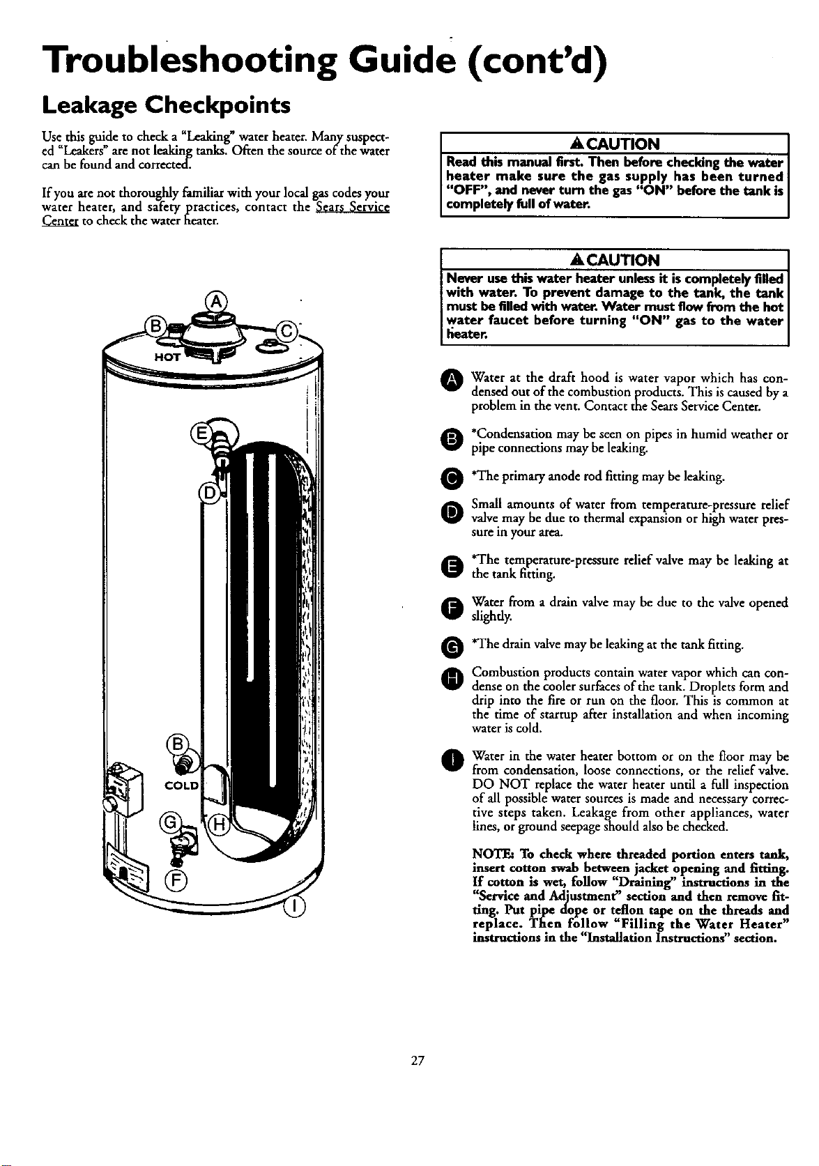
Troubleshooting Guide (cont'd)
Leakage Checkpoints
Use this guide to check a _Leaking_ water heater. Many suspect-
ed "Leakers" are not leaking tanks. Often the source of the water
can be found and corrected.
If you arenot thoroughly familiar with your local gas codes your
water heater, and safety practices, contact the
Center to check the water heater.
A CAUTION [
Read this manual first. Then before checking the water ]
heater make sure the gas supply has been turned[
"OFF", and never turn the gas"ON" before the tank is
comp etely fo of water.
A CAUTION
Never usethis water heater unlessit iscompletely filled
with water, To prevent damage to the tank, the tank I
must be filled with water. Water must flow from the hot I
water faucet before turning "ON" gas to the water
fieater.
O Water at the draft hood is water which has con-
vapor
densed out of the combustion products. This is caused by a
problem in the vent. Contact the SearsService Center.
O *Condensation may be seen on pipes in humid weather or
pipe connections may be leaking.
Q'The primary anode rod fitting may be leaking.
Small amounts of water from temperature-pressure relief
Q valve,may be due to thermal expansion or high water pres-
sure m your area.
*The temperature-pressure relief valve may be leaking at
the tank fitting.
Water from a drain valve may be due to the valve opened
slightly.
*The drain valve may be leaking at the tank fitting.
Combustion products contain water vapor which can con-
dense on the cooler surfaces of the tank. Droplets form and
drip into the fire or run on the floor. This is common at
the time of starrup after installation and when incoming
water is cold.
Water in the water heater bottom or on the floor may be
from condensation, loose connections, or the relief valve.
DO NOT replace the water heater until a full inspection
of all possible water sources is made and necessary correc-
tive steps taken. Leakage from other appliances, water
lines, or ground seepage snould also be checked.
NOTE: To check where threaded portion enters tank,
insert cotton swab between jacket opening and fitting.
If cotton is wet, follow "Draining" instructions in the
"Service and Adjustment" section and then remove fit-
ting. Put pipe dope or teflon tape on the threads and
replace. Then follow "Filling the Water Heater"
instructions in the "Installation Instructions" section.
27
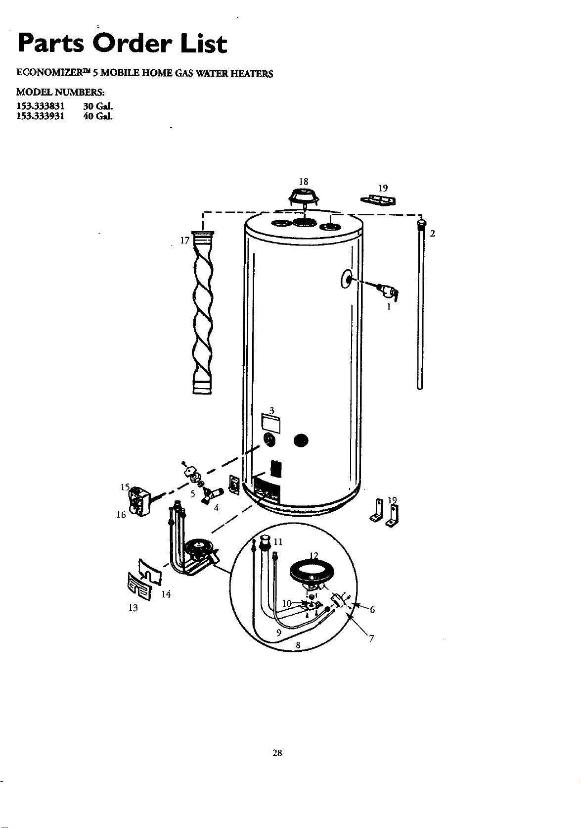
Parts Order List
ECONOMIZER TM 5 MOBILE HOME GAS WATER HEATERS
MODEL NUMBERS:
153.333831 30 Gal.
153.333931 40 Gal.
18
1
@14
13
28
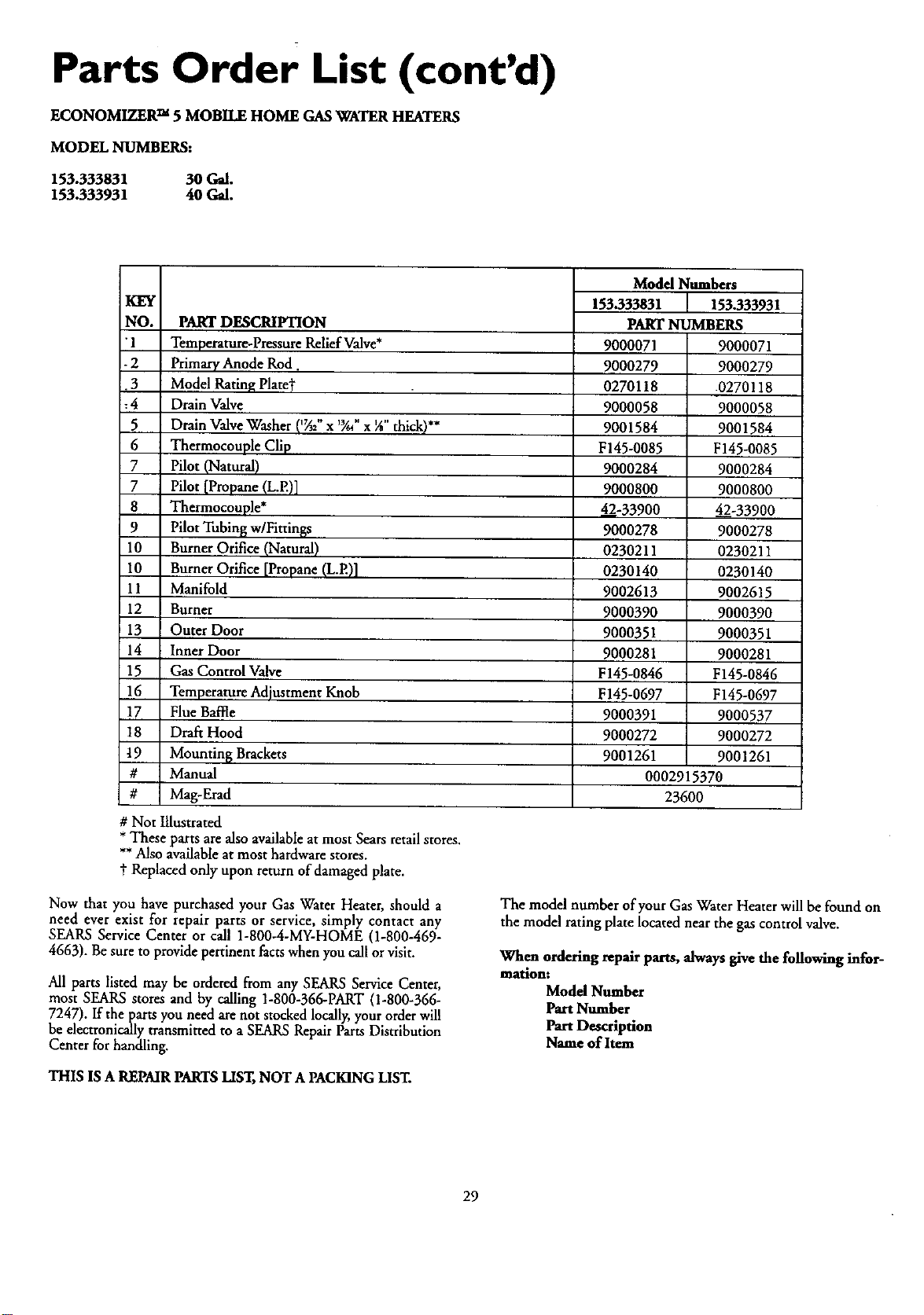
Parts Order List (cont'd)
ECONOMIZER TM 5 MOBILE HOME GAS WATER HEATERS
MODEL NUMBERS:
153.333831 30 Gal.
153.333931 40 Gal.
KEY
NO. PART DESCRIPTION
"1 Temperature-PressureReliefValve*
- 2 Primary Anode Rod.
•3 Model Rating Plaret
:4 Drain Valve
5 Drain Valve Washer (_z" x "/." x IA"thick)**
6 Thermocouple Clip
7 Pilot (Natural)
7 Pilot [Propane (L.E)]
8 Thermocouple*
9 Pilot Tubing w/Fitrin_s
10 Burner Orifice (Natural)
10 Burner Orifice [Propane (L.E)]
11 Manifold
12 Burner
13 Outer Door
14 Inner Door
15 Gas Control Valve
16 Temperature Adjustment Knob
17 Flue Baffle
18 Draft Hood
9 Mountin_ Brackets
# Manual
# Mag-Erad
Model Numbers
153.333831 153.333931
PART NUMBERS
9000071 9000071
9000279 9000279
0270118 .0270118
9000058 9000058
9001584 9001584
F145-0085 F145-0085
9000284 9000284
9000800 9000800
42-33900 4._2-33900
9000278 9000278
0230211 0230211
0230140 0230140
9002613 9002615
9000390 9000390
9000351 9000351
9000281 9000281
F145-0846 F145-0846
F145-0697 F145-0697
9000391 9000537
9000272 9000272
9001261 9001261
0002915370
23600
# Not Illustrated
* These parts are also available at most Sears retail stores.
** Also available at most hardware stores.
t Replaced only upon return of damaged plate.
Now that you have purchased your Gas Water Heater, should a
need ever exist for repair parts or service, simply contact any
SEARS Service Center or call 1-800-4-MY-HOME (1-800-469-
4663). Be sure to provide pertinent facts when you call or visit.
All parts listed may be ordered from any SEARS Service Center,
most SEARS stores and by calling 1-800-366-PART (1-800-366-
7247). If the parts you need are not stocked locally, your order will
be electronically transmitted to a SEARS Repair Parts Distribution
Center for handling.
THIS lS A REPMR PARTSLIST,NOT A PACKINGLIST.
The model number of your Gas Water Heater will be found on
the model rating plate located near the gas control valve.
When ordering repair parts, always give the following infor-
matlont
Model Number
Part Number
Part Description
Name of Item
29

Notes
30

Notes
31
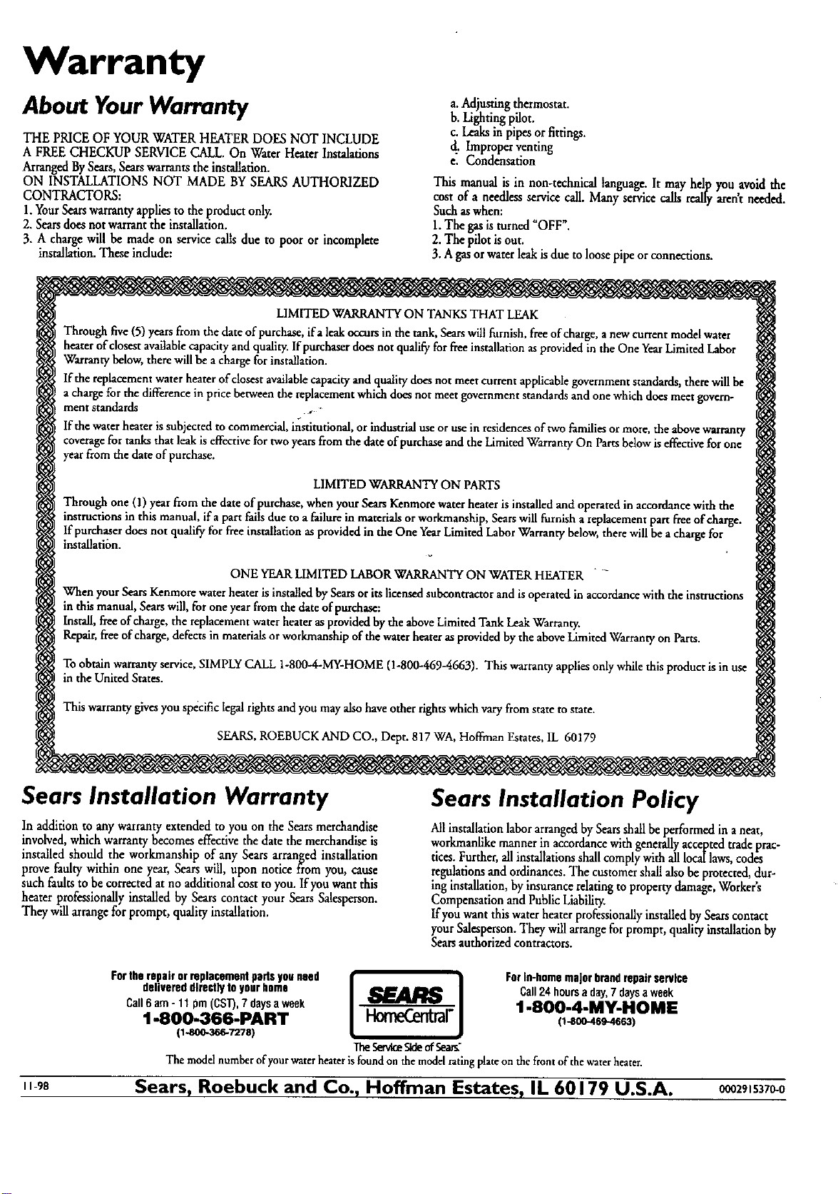
Warranty
About Your Warranty
THE PRICE OF YOUR WATER HEATERDOES NOT INCLUDE
A FREE CHECKUP SERVICECALL.On Water Heater Instalations
ArrangedBySears,Searswarrants theinstallation.
ON INSTALLATIONS NOT MADE BY SEARSAUTHORIZED
CONTRACTORS:
1.YourSearswarrantyappliesto the product only.
2. Searsdoesnotwarrantthe installation.
3. A chargewill be made on service callsdue to poor or incomplete
installation.Theseindude:
a.Adjusting thermostat.
b.Lightingpilot.
c. Leaksin pipes orfittings.
d. Improper venting
e. Condensation
This manualis in non-technicallanguage.It may help youavoid the
cost of a needlessservicecall. Manyservicecalls reallyarent needed.
Suchaswhen:
1.The gasis turned_OFF'.
2.Thepilot isout.
3.A gasorwaterleakisdueto loosepipeorconnections.
LIMITEDWARRANTYON TANKSTHAT LEAK
Throughfive(5)yearsfrom the dateofpurchase,ifa leakoccursinthe tank,Searswill furnish,freeofcharge,a newcurrentmodelwater
heaterofclosestavailableopacity and quality.If porchaserdoesnot qualifyfor freeinstallationasprovidedin the One YearLimitedLabor
Wasrantybelow,there willbe a chargeforinstallation.
lfthe replacementwaterheaterofdosest availablecapacityand qualitydoesnot meetcurrent applicablegovernmentstandards,therewillbe
a chargeforthe differencein pricebetweenthe replacementwhichdoesnotmeetgovernmentstandardsand onewhichdoesmeetgovern-
ment standards ,-
If thewater heaterissubjectedto commercial,institutional,orindustrialuseorusein residencesof twofamiliesormore,the abovewarranty
coveragefortanks that leakiseffectivefor twoyearsfrom the dateofpurchaseand theLimitedWarrantyOn Partsbelowiseffectivefor one
yearfrom the dateofpurchase.
LIMITEDWARRANTYON PARTS
Through one (1)year from the date of purchase,whenyourSearsKenmorewaterheateris installedand operatedin accordancewith the
instructionsin this manual, ifa part failsdue to afailurein materialsorworkmanship,Searswill furnish a replacementpart fleeofcharge.
If purchaserdoesnot qualify forfreeinstallationas providedin the One YearLimitedLabor Warrantybelow,therewillbe a chargefor
instalfation.
ONE YEARLIMITEDLABORWARRANTYON WATERHEATER " -
When yourSearsKenmorewaterheaterisinstalledbySearsor itslicensedsubcontractorand isoperatedin accordancewith the instsucxions
in this manual,Searswill,for one yearfromthe dateof purchase:
Install,freeofcharge,the replacementwaterheaterasprovidedby the aboveLimitedTankLeakWarranty.
Repair,freeof charge,defectsin materialsor workmanshipofthe waterheaterasprovidedbythe aboveLimitedWarrantyon Parts.
To obtain warranty service, SIMPLY CALL 1-800-4-MY-HOME (1-800-469-4663). This warranty applies only while this product is in use
in the United States.
This warrantygives you specific legal rightsand you may also have other rights which vary from state to state.
SEARS, ROEBUCK AND CO., Dept. 817 WA, Hoffman Estates,1L 60179
Sears Installation Warranty
In addition to any warranty extended to you on the Sears merchandise
involved, which warranty becomes effective the date the merchandise is
installed should the workmanship of any Sears arranged installation
prove faulty within one year, Sears will, upon notice from you, cause
such faults to be corrected at no additional cost to you. If you want this
heater professionally installed by Sears contact your Sears Salesperson.
They will arrange for prompt, quality installation.
Sears Installation Policy
AllinstallationlaborarrangedbySeatsshallbeperformedin aneat,
workmanlikemanner in accordancewithgenerallyacceptedtradeprac-
tices.Further,allinstallationsshallcomplywithalllocallaws,codes
regulationsand ordinances.The customershallalsobeprotected,dur-
inginstallation,by insurancerelatingto propertydamage,Worker's
Compensationand PublicLiability.
Ifyou wantthiswater heaterprofessionallyinstalledby Searscontact
yourSalesperson.Theywillarrangeforprompt, qualityinstallationby
Searsauthorizedcontractors.
Fortherepairorreplacementparisyouneed _. ]1 Forin-homemajorbrandrepairservice
delivereddirectlytoyourhome Call24hoursaday,7daysaweek
Call6am-110m(CST),7daysaweek 1-800-4-MY-HOME
1-800-366-PART _1_1 1,-8oo-4_-46_)
(1_0-366-7278) •
lhe SereneSideof5ee_"
The modelnumberofyourwaterheaterisfoundonthemodelratingplateonthefrontofthewaterheater.
_gs Sears, Roebuck and Co., Hoffman Estates, IL 60179 U.S.A. _zg_s37_0