Loading ...
Loading ...
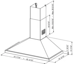
44" AGA Rangehood
Model # AMCHD44
3
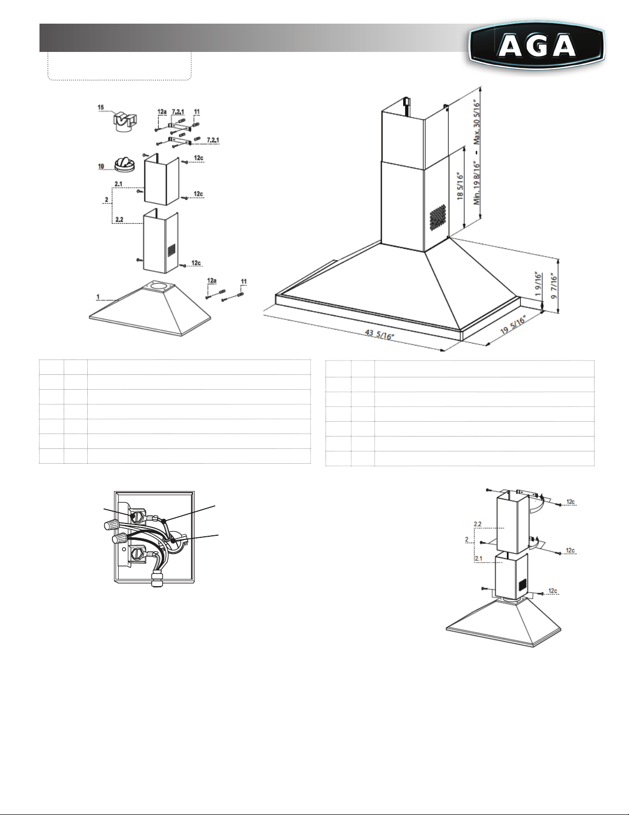
ELECTRICAL CONNECTION
• Remove the cover from the Field Wiring Compartment with a
Phillips screwdriver.
• Feed the Power Supply Cable through the electrical knockout.
Connect the Power Supply Cable to the rangehood cable.
Attach the Power Supply Cable grounding lead to the green
screw provided. Attach the White lead of the power supply
to the White lead of the rangehood with a twist-on type
wire connector. Attach the Black lead of the power supply
to the Black lead of the rangehood with a twist on type wire
connector.
• Replace the cover.
CHIMNEY ASSEMBLY
Upper Exhaust Chimney
• Slightly widen the two
sides of the upper
chimney and hook them
behind the brackets
7.2.1, making sure that
they are well seated.
• Secure the sides to the
brackets using the 4
screws 12c supplied.
Lower Exhaust Chimney
• Slightly widen the two sides of the chimney and hook
them between the upper chimney and the wall, making
sure that they are well seated.
• Fix the lower part laterally to the hood body using the 2
screws 12c supplied.
Dimensions
and Parts
Ref Qty
Product Components
1 1
Hood Body, complete with: Controls, Light, Blower,Filters
2 1
1 Telescopic Chimney comprising:
2.1 1
Upper Section
2.2 1
Lower Section
10 1
Damper
15 1
Air Outlet Connection
Ref Qty
Installation Components
7.2.1 2
Upper Chimney Section Fixing Brackets
11 6
Wall Plugs (if supplied)
12a 6
Screws 3/16" x 1 3/4"
12c 6
Screws 1/8" x 3/8"
Qty
Documentation
1
Instruction Manual
Specifi cations are subject to change without notice. Visit www.aga-ranges.com for the most up-to-date information.
EN
1
12
ELECTRICAL CONNECTION
• Remove the cover from the Field Wiring Com-
partment with a Phillips screwdriver.
• Feed the Power Supply Cable through the electrical
knockout. Connect the Power Supply Cable to the
rangehood cable. Attach the Power Supply Cable
grounding lead to the green screw provided. Attach
the White lead of the power supply to the White
lead of the rangehood with a twist-on type wire
connector. Attach the Black lead of the power sup-
ply to the Black lead of the rangehood with a twist-
on type wire connector.
• Replace the cover.
For the 36"
Knockout is located in the junction box on the lef
t
side of the hood facing the front approx. 9-3/8" from
the left to the right and 3-3/8" up from the bottom o
f
the hood.
For the 44" model
Knockout is located in the junction box on the Left
side of the hood facing the front approx. 13-3/8" from
the left to the right and 3-3/8" up from the bottom o
f
hood.
Chimney assembly
Upper exhaust Chimney
• Slightly widen the two sides of the upper chimney
and hook them behind the brackets 7.2.1, making
sure that they are well seated.
• Secure the sides to the brackets using the 4 screws
12c supplied.
Lower exhaust Chimney
• Slightly widen the two sides of the chimney and
hook them between the upper chimney and the
wall, making sure that they are well seated.
• Fix the lower part laterally to the hood body using
the 2 screws 12c supplied.