Loading ...
Loading ...
Loading ...
MAINTENANCE
ENGINE MAINTENANCE
Use thefollowingmaintenance sectionto keep
your unit in good operating condition. All the
maintenance information for the engine is in
the =Engine InstructionBook". Beforeyou start
the engine, read this book.
• Hard starting.
Engine smoking.
• Spark plug fouling.
• Oil or gas saturation of the air filter.
WARNING: Before you make an
inspection, adjustment (except
carburetor), or repair, stop the
engine and disconnect the wire
from the spark plug.
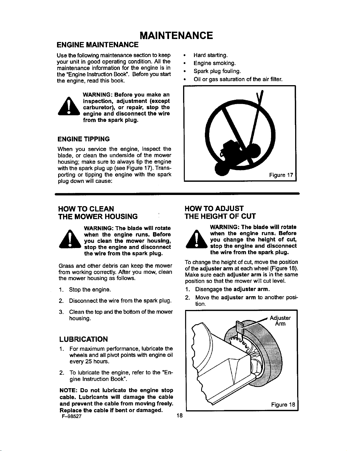
ENGINE TIPPING
When you service the engine, inspect the
blade, or clean the underside of the mower
housing; make sure to always tip the engine
with the spark plug up (see Figure 17). Trans-
porting or tipping the engine with the spark
plug down will cause:
Figure 17
HOW TO CLEAN
THE MOWER HOUSING
WARNING: The blade will rotate
_k when the engine runs. Before
you clean the mower housing,
stop the engine and disconnect
the wire from the spark plug.
Grass and other debris can keep the mower
from working correctly. After you mow, clean
the mower housing as follows.
1. Stop the engine.
2. Disconnect the wire from the spark plug.
3. Clean the top and the bottomof the mower
housing.
LUBRICATION
1. For maximum performance, lubricate the
wheels and all pivot points with engine oil
every 25 hours.
2. To lubricate the engine, refer to the "En-
gine Instruction Book".
NOTE: Do not lubricate the engine stop
cable. Lubricants will damage the cable
and prevent the cable from moving freely.
Replace the cable if bent or damaged.
F-98527
HOW TO ADJUST
THE HEIGHT OF CUT
WARNING: The blade will rotate
when the engine runs, Before
you change the heigh t of cut,
stop the engine and disconnect
the wire from the spark plug.
To change the heightof cut, move the position
of the adjuster arm at each wheel (Figure 18).
Make sure each adjuster arm is in the same
position sothat the mower will cut level.
1. Disengage the adjuster arm.
2. Move the adjuster arm to another posi-
tion.
Adjuster
Arm
18
Figure 18
Loading ...
Loading ...
Loading ...