
EnglishFrançaisEspañol
MODELS
RX09RMVJU
RX12RMVJU
RX15RMVJU
RX18RMVJU
RX24RMVJU
RX09RMVJU9
RX12RMVJU9
RX18RMVJU9
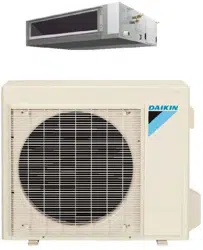
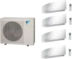
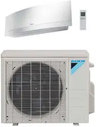
DAIKIN ROOM AIR CONDITIONER
INSTALLATION MANUAL
R410A Split Series
Installation manual
Manuel dinstallation
Manual de instalación
Manuel dinstallation
00_CV_3P500432-2B.indd 1 10/30/2018 11:15:19 AM
1 ■English
Contents
Safety Considerations .................................... 1
Accessories ..................................................... 3
Precautions for Selecting a Location ........... 3
Precautions on Installation ............................ 4
Outdoor Unit Installation Diagram ................ 4
Installation Space Requirements .................. 5
Outdoor Unit Installation ................................ 5
1. Installing the outdoor unit ............................................ 5
2. Drain work ................................................................... 6
3. Flaring the pipe end ..................................................... 6
4. Refrigerant piping ........................................................ 6
5. Pressure test and evacuating system .......................... 7
6. Rellingrefrigerant ...................................................... 8
7. Refrigerant piping work .............................................. 8
Wiring ............................................................... 9
Facility Setting
(cooling at low outdoor temperature) ........... 11
Pump Down Operation ................................... 11
Trial Operation and
Testing ........................... 12
1. Trial operation and testing ........................................... 12
2. Test items .................................................................... 12
Safety Considerations
Read these Safety Considerations for Installation carefully
before installing an air conditioner or heat pump. After completing
the installation, make sure that the unit operates properly during
the startup operation.
Instruct the user on how to operate and maintain the unit.
Inform users that they should store this installation manual with
the operation manual for future reference.
Always use a licensed installer or contractor to install this product.
Improper installation can result in water or refrigerant leakage,
electricshock,re,orexplosion.
Meanings of DANGER, WARNING, CAUTION, and NOTE
Symbols:
DANGER
...........
Indicates an imminently hazardous
situation which, if not avoided, will
result in death or serious injury.
WARNING
.........
Indicates a potentially hazardous
situation which, if not avoided, could
result in death or serious injury.
CAUTION
..........
Indicates a potentially hazardous
situation which, if not avoided, may
result in minor or moderate injury.
It may also be used to alert against
unsafe practices.
NOTE
................
Indicates situations that may result
in equipment or property-damage
accidents only.
DANGER
• Refrigerantgasisheavierthanairandreplacesoxygen.
Amassiveleakcanleadtooxygendepletion,especially
inbasements,andanasphyxiationhazardcouldoccur
leading to serious injury or death.
•
Do not ground units to water pipes, gas pipes, telephone
wires, or lightning rods as incomplete grounding can cause
a severe shock hazard resulting in severe injury or death.
Additionally, grounding to gas pipes could cause a gas leak
andpotentialexplosioncausingsevereinjuryordeath.
• If refrigerant gas leaks during installation, ventilate the
areaimmediately.Refrigerantgasmayproducetoxicgas
ifitcomesintocontactwithre.Exposuretothisgascould
cause severe injury or death.
• After completing the installation work, check that the
refrigerant gas does not leak throughout the system.
• Donotinstallunitinanareawhereammablematerials
arepresentduetoriskofexplosionsthatcancause
serious injury or death.
• Safely dispose all packing and transportation materials
in accordance with federal/state/local laws or ordinances.
Packing materials such as nails and other metal or
wood parts, including plastic packing materials used for
transportation may cause injuries or death by suffocation.
WARNING
• Onlyqualiedpersonnelmustcarryouttheinstallation
work. Installation must be done in accordance with this
installation manual. Improper installation may result in
waterleakage,electricshock,orre.
• When installing the unit in a small room, take measures
tokeeptherefrigerantconcentrationfromexceeding
allowablesafetylimits.Excessiverefrigerantleaks,inthe
event of an accident in a closed ambient space, can lead
tooxygendeciency.
• Useonlyspeciedaccessoriesandpartsforinstallation
work.Failuretousespeciedpartsmayresultinwater
leakage,electricshock,re,ortheunitfalling.
• Install the air conditioner or heat pump on a foundation
strong enough that it can withstand the weight of the unit.
Afoundationofinsufcientstrengthmayresultintheunit
falling and causing injuries.
• Take into account strong winds, typhoons, or earthquakes
when installing. Improper installation may result in the unit
falling and causing accidents.
01_EN_3P500432-2B.indd 1 10/30/2018 11:53:01 AM
2■English
• Make sure that a separate power supply circuit is provided
for this unit and that all electrical work is carried out by
qualiedpersonnelaccordingtolocal,state,andnational
regulations.Aninsufcientpowersupplycapacityor
improper electrical construction may lead to electric shock
orre.
• Makesurethatallwiringissecured,thatspeciedwires
areused,andthatnoexternalforcesactontheterminal
connections or wires. Improper connections or installation
mayresultinre.
• When wiring, position the wires so that the electrical
wiringboxcovercanbesecurelyfastened.Improper
positioningoftheelectricalwiringboxcovermayresultin
electricshock,re,ortheterminalsoverheating.
• Before touching electrical parts, turn off the unit.
• The circuit must be protected with safety devices in
accordance with local and national codes, i.e. a circuit
breaker.
•
Securely fasten the outdoor unit terminal cover (panel). If the
terminal cover/panel is not installed properly, dust or water
mayentertheoutdoorunitcausingreorelectricshock.
•
When installing or relocating the system, keep the refrigerant
circuitfreefromsubstancesotherthanthespecied
refrigerant (R410A) such as air. Any presence of air or other
foreign substance in the refrigerant circuit can cause an
abnormal pressure rise or rupture, resulting in injury.
• Do not change the setting of the protection devices. If the
pressure switch, thermal switch, or other protection device
is shorted and operated forcibly, or parts other than those
speciedbyDaikinareused,reorexplosionmayoccur.
CAUTION
• Donottouchtheswitchwithwetngers.Touchingaswitch
withwetngerscancauseelectricshock.
• Do not allow children to play on or around the unit to
prevent injury.
• Theheatexchangernsaresharpenoughtocut.Toavoid
injurywearglovesorcoverthenswhileworkingaround
them.
• Do not touch the refrigerant pipes during and immediately
after operation as the refrigerant pipes may be hot or
cold,dependingontheconditionoftherefrigerantowing
through the refrigerant piping, compressor, and other
refrigerant cycle parts. Your hands may suffer burns or
frostbite if you touch the refrigerant pipes. To avoid injury,
give the pipes time to return to normal temperature or, if
you must touch them, be sure to wear proper gloves.
•
Install drain piping to ensure proper drainage. Improper drain
piping may result in water leakage and property damage.
• Insulate piping to prevent condensation.
• Be careful when transporting the product.
• Do not turn off the power immediately after stopping
operation. Always wait for at least 5 minutes before turning
off the power. Otherwise, water leakage may occur.
• Do not use a charging cylinder. Using a charging cylinder
may cause the refrigerant to deteriorate.
• Refrigerant R410A in the system must be kept clean, dry,
and tight.
(a) Clean and Dry -- Foreign materials (including mineral
oils such as SUNISO oil or moisture) should be
prevented from getting into the system.
(b)
Tight -- R410A does not contain any chlorine, does not
destroy the ozone layer, and does not reduce the earth’s
protection again harmful ultraviolet radiation. R410A
can contribute to the greenhouse effect if it is released.
Therefore take proper measures to check for the tightness
of the refrigerant piping installation. Read the chapter
Refrigerant Piping Work and follow the procedures.
• Since R410A is a blend, the required additional refrigerant
must be charged in its liquid state. If the refrigerant is
charged in a state of gas, its composition can change and
the system will not work properly.
• The indoor unit is for R410A. See the catalog for indoor
models that can be connected. Normal operation is not
possible when connected to other units.
•
Remote controller (wireless kit) transmitting distance can be
shorterthanexpectedinroomswithelectronicuorescent
lamps (inverter or rapid start types). Install the indoor unit
farawayfromuorescentlampsasmuchaspossible.
• Indoor units are for indoor installation only. Outdoor units
can be installed either outdoors or indoors.
• Do not install the air conditioner or heat pump in the
following locations:
(a) Where a mineral oil mist or oil spray or vapor is
produced,forexample,inakitchen.
Plastic parts may deteriorate and fall off or result in
water leakage.
(b) Where corrosive gas, such as sulfurous acid gas, is
produced.
Corroding copper pipes or soldered parts may result in
refrigerant leakage.
(c) Near machinery emitting electromagnetic waves.
Electromagneticwavesmaydisturbtheoperationof
the control system and cause the unit to malfunction.
(d)
Whereammablegasmayleak,wherethereiscarbon
ber,orignitabledustsuspensionintheair,orwhere
volatileammablessuchasthinnerorgasolinearehandled.
Operatingtheunitinsuchconditionscancauseare.
• Take adequate measures to prevent the outdoor unit
from being used as a shelter by small animals. Small
animals making contact with electrical parts can cause
malfunctions,smoke,orre.Instructtheusertokeepthe
area around the unit clean.
NOTE
•
The outdoor unit should be positioned where the unit and power
supply wires (breaker panel to outdoor unit) are at least 10ft (3m)
away from any televisions or radios. (The unit may cause interference
with the picture or sound.) Depending on the radio waves, a distance
of10ft(3m)maynotbesufcienttoeliminatethenoise.
• Dismantling the unit, treatment of the refrigerant, oil and
additional parts must be done in accordance with the
relevant local, state, and national regulations.
•
Do not use the following tools that are used with
conventional refrigerants: gauge manifold, charge hose, gas
leakdetector,reverseowcheckvalve,refrigerantcharge
base, vacuum gauge, or refrigerant recovery equipment.
• If the conventional refrigerant and refrigerator oil are
mixedinR410A,therefrigerantmaydeteriorate.
• This air conditioner or heat pump is an appliance that
should not be accessible to the general public.
• Asdesignpressureis604psi,thewallthicknessofeld-
installed pipes should be selected in accordance with the
relevant local, state, and national regulations.
RN003-U
English
01_EN_3P500432-2B.indd 2 10/30/2018 11:53:01 AM
3 ■English
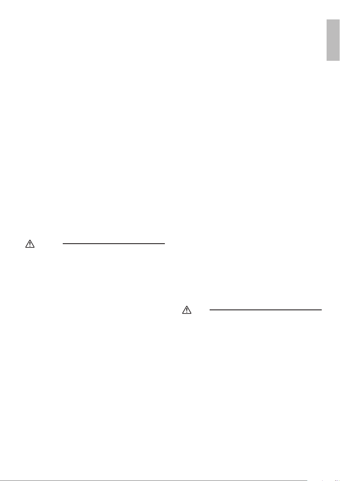
Accessories
1
Installation manual
A
This is at the bottom of the packaging.
1
Drain socket
B
4
6
09/12 class
15/18/24 class
1
2
3
09/12 class
15/18/24 class
Drain cap (1)
C
Drain cap (2)
D
Warranty
E
Precautions for Selecting a Location
1) Chooseaplacesolidenoughtobeartheweightandvibrationoftheunit,wheretheoperatingsoundwillnotbeamplied.
2) Choose a location where the hot air discharged from the unit or the operating sound will not cause a nuisance to the
neighbors of the user.
3) Avoid locations, such as near bedrooms, where the operating sound may cause disturbance.
4) Theremustbesufcientspacetocarrytheunitintoandoutofthesite.
5) Theremustbesufcientspaceforairpassageandnoobstructionsaroundtheairinletandtheairoutlet.
6) Thesitemustnotbepronetoammablegasleaksinthesurroundingarea.
7) In coastal areas or other places with a salty atmosphere or one containing sulfate gas, corrosion may shorten the life of the air
conditioner.
8) Sincewaterwillowfromthedrainoftheoutdoorunit,donotplaceundertheunitanythingwhichmustbekeptawayfrom
moisture.
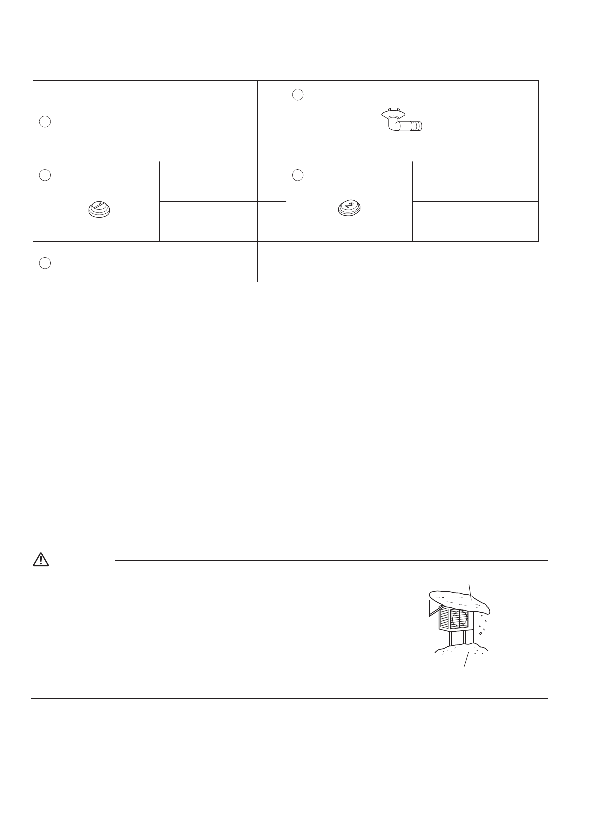
NOTE
Cannot be installed suspended from a ceiling or stacked.
CAUTION
When operating the air conditioner in a low outdoor ambient temperature, be sure to
follow the instructions described below.
• Topreventexposuretowind,installtheoutdoorunitwithitssuction side facing the
wall.
• Neverinstalltheoutdoorunitatasitewherethesuctionsidemaybeexposed
directly to wind.
• Topreventexposuretowind,itisrecommendedtoinstallabafeplateontheair
discharge side of the outdoor unit.
• In heavy snow areas, select an installation site where the snow will not affect the unit.
•Construct a large canopy.
•Construct a pedestal.
Install the unit high enough off
the ground to prevent burying
in snow.
01_EN_3P500432-2B.indd 3 10/30/2018 11:53:01 AM
4■English
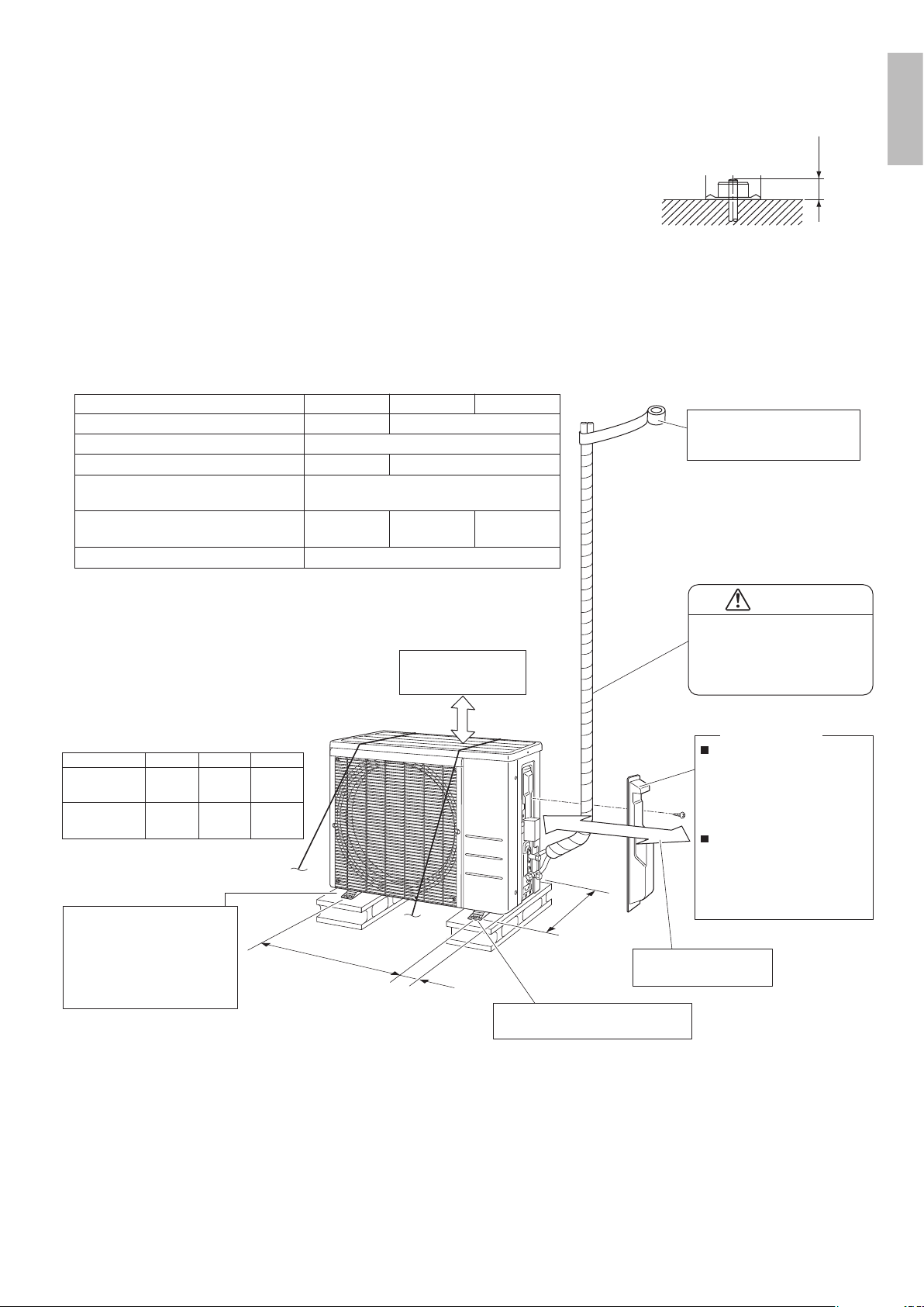
Precautions on Installation
• Check the strength and level of the installation surface so that the unit does not
cause any operating vibrations or noise after installation.
• Fixtheunitinplacesecurelyusingfoundationbolts,asinthegure.(Prepare4
sets of 5/16 inch (M8) or 3/8 inch (M10) foundation bolts, nuts and washers; all
separately available.)
• It is best to screw in the foundation bolts until their ends are 3/4 inch (20mm)
from the foundation surface.
3/4”
(20mm)
Outdoor Unit Installation Diagram
In sites with poor drainage,
use block bases for the
outdoor unit.
Adjust foot height until the unit
is level. Otherwise, water
leakage or pooling of water
may occur.
Appearance of outdoor units may differ from some models.
O.D. 3/8 inch
(9.5mm)
Gas pipe
Liquid pipe O.D. 1/4 inch (6.4mm)
0.21oz/ft (20g/m)
Max. allowable piping length
49-1/4ft (15m)
65-5/8ft (20m)
Max. allowable piping height
Additional refrigerant required for refrigerant
pipe exceeding 32.8ft (10m) in length.
*
Be sure to add the proper amount of additional refrigerant.
Failure to do so may result in reduced performance.
**The suggested shortest pipe length is 10ft (3m), in order to avoid
noise from the outdoor unit and vibration.
(Mechanical noise and vibration may occur depending on how
the unit is installed and the environment in which it is used.)
10ft (3m)
O.D. 1/2 inch
(12.7mm)
O.D. 5/8 inch
(15.9mm)
RX15/18∗RX09/12∗
65-5/8ft (20m)
98-1/2ft (30m)
Min. allowable piping length
X
(Foot bolt-hole centers)
(From unit’s side)
(Foot bolt-hole
centers)
Y
**
*
RX24∗
Allow 11-13/16” (300mm)
of work space below the
ceiling surface.
Where there is a danger of the unit
falling, use foot bolts, or wires.
18-1/2
inch
(470mm)
23-5/8
inch
(600mm)
12-1/8
inch
(308mm)
13-5/8
inch
(346mm)
3-13/16
inch
(97mm)
4-15/16
inch
(125mm)
15/18/24 class
09/12 class
X Y
Z
CAUTION
Keep the piping length between
10ft (3m) and 65-5/8ft (20m)
(for 09/12 class),
10ft (3m) and 98-1/2ft (30m)
(for 15/18/24 class).
9-13/16
”
(250mm) from wall
How to remove the stop
valve cover
1) Remove the screw on the
stop valve cover.
2) Slide the stop valve cover
downward to remove it.
1) Insert the upper part of
the stop valve cover into
the outdoor unit.
2) Tighten the screw.
How to attach the stop
valve cover
Stop valve cover
Wrap the insulation pipe with
finishing tape from bottom to
top.
Allow space for piping
and electrical servicing.
Z
English
01_EN_3P500432-2B.indd 4 10/30/2018 11:53:01 AM
5 ■English
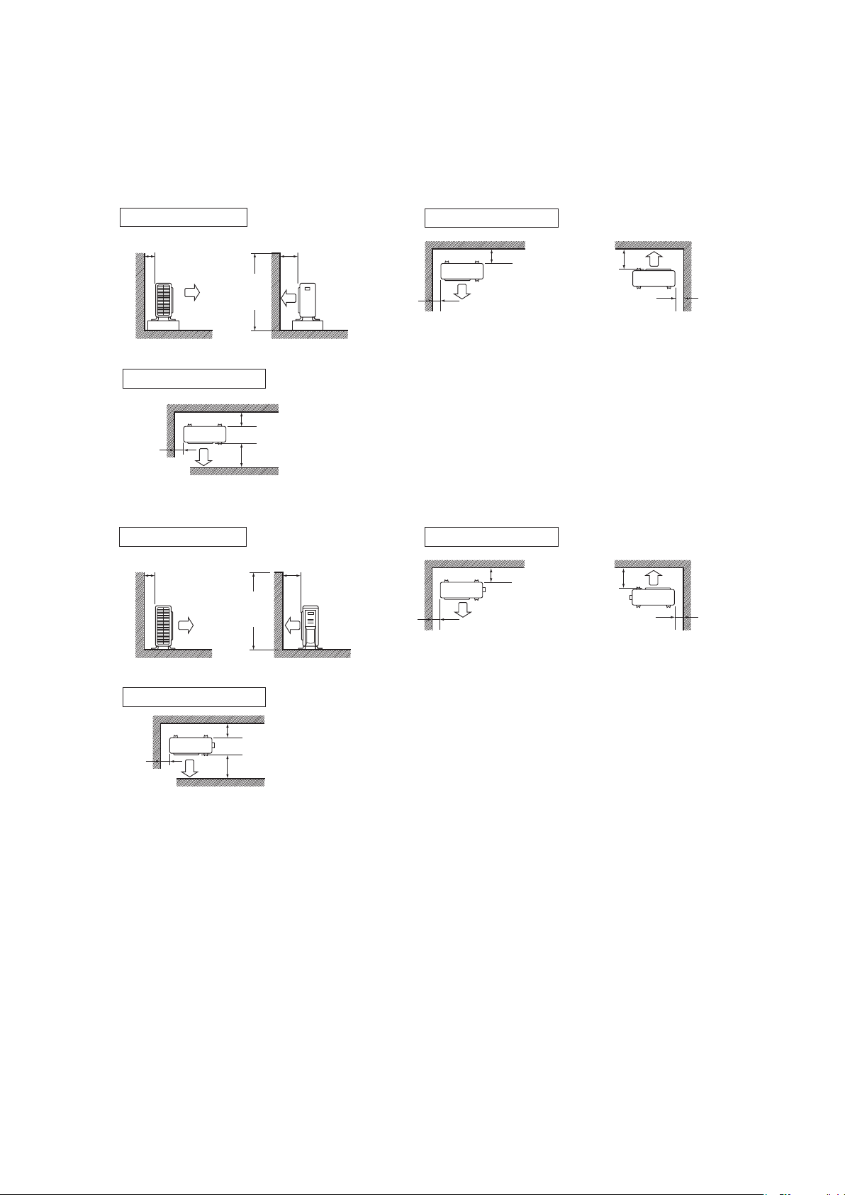
Installation Space Requirements
•
Position the unit on a horizontal surface. Any tilt in the unit should be 3° or less to the horizontal.
•
Whereawallorotherobstacleisinthepathoftheoutdoorunit’sintakeorexhaustairow,followtheinstallationspace
requirements below.
• For any of the below installation patterns, the wall height on the outlet side should be 47-1/4 inch (1200mm) or less.
More than
1-15/16 (50)
More than
1-15/16 (50)
More than
5-7/8 (150)
More than
3-15/16 (100)
More than
1-15/16 (50)
More than
3-15/16 (100)
Side view
47-1/4
(1200)
or less
Wall facing one side
Walls facing two sides
Top view
Top view
More than 5-7/8 (150)
More than
11-13/16 (300)
More than
1-15/16 (50)
Walls facing three sides
unit: inch (mm)
unit: inch (mm)
Top view
More than 3-15/16 (100)
More than
13-3/4 (350)
More than
1-15/16 (50)
Walls facing three sides
More than
3-15/16 (100)
More than
13-3/4 (350)
Side view
47-1/4
(1200)
or less
Wall facing one side
More than
1-15/16 (50)
More than
1-15/16 (50)
Top view
More than
3-15/16 (100)
Walls facing two sides
More than
13-3/4 (350)
09/12 class
15/18/24 class
Outdoor Unit Installation
1. Installing the outdoor unit
1)
When installing the outdoor unit, refer to “Precautions for Selecting a Location” and the “Outdoor Unit Installation Diagram”.
2) Ifdrainworkisnecessary,followtheproceduresonthenextpage.
01_EN_3P500432-2B.indd 5 10/30/2018 11:53:01 AM
6■English
2. Drain work
• Ifthedrainportiscoveredbyamountingbaseoroor
surface, place additional foot bases of at least 1-1/4
inch (30mm) in height under the outdoor unit’s feet.
• In cold areas, do not use a drain socket, drain caps
(1,2) and a drain hose with the outdoor unit. (Drain
water may freeze, impairing heating performance.)
1) Attach
C
drain cap (1) and
D
drain cap (2).
2) Attach
B
drain socket.
• When attaching
B
drain socket to the bottom
frame, make sure to connect the drain hose to the
drainsocketrst.
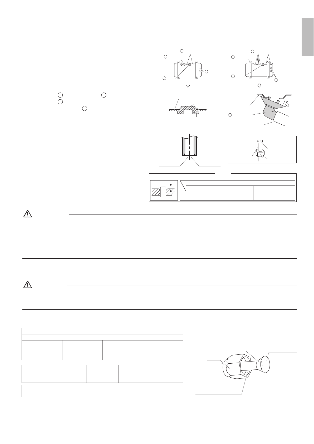
3. Flaring the pipe end
1) Cut the pipe end with a pipe cutter.
2) Remove burrs with the cut surface facing
downward,sothatthelingsdonotenterthe
pipe.
3) Putthearenutonthepipe.
4) Flare the pipe.
5) Checkthatthearinghasbeendonecorrectly.
Check
The flare's
inner surface
must be
flaw-free.
The pipe end must
be evenly flared in
a perfect circle.
Make sure that the
flare nut is fitted.
Set exactly at the position shown below.
Flaring
A
Die
A
0-0.020 inch
(0-0.5mm)
Clutch-type
Flare tool for R410A
0.039-0.059 inch
(1.0-1.5mm)
Clutch-type (Rigid-type)
0.059-0.079 inch
(1.5-2.0mm)
Wing-nut type (Imperial-type)
Conventional flare tool
Cut exactly at
right angles.
Remove burrs.
WARNING
• Donotapplymineraloiltotheare.
• Prevent mineral oil from getting into the system as this would reduce the service life of the units.
• Never use piping which has been used for previous installations. Only use parts which are delivered with this unit.
• Never install a dryer to this R410A unit in order to guarantee its service life.
• The drying material may dissolve and damage the system.
• Incompletearingmayresultinrefrigerantgasleakage.
4. Refrigerant piping
CAUTION
• Usethearenutxedtothemainunit.(Thisistopreventthearenutfromcrackingasaresultofdeteriorationovertime.)
• Topreventgasleakage,applyrefrigerationoilonlytotheinnersurfaceoftheare.(UserefrigerationoilforR410A.)
• Useatorquewrenchwhentighteningthearenutstopreventdamagetothearenutsandgasleakage.
• Alignthecentersofbotharesandtightenthearenuts3or4turnsbyhand,thentightenthemfullywithaspanneranda
torque wrench.
Do not apply refrigeration
oil to the outer surface.
Flare nut
Apply refrigeration
oil only to the inner
surface of the flare.
Do not apply refrigeration oil to
the flare nut to avoid tightening
with excessive torque.
Apply oil
Flare nut tightening torque
Gas side
3/8 inch (9.5mm)
1/2 inch (12.7mm)
24-1/8 –29-1/2lbf • ft
(32.7-39.9N • m)
36-1/2 –44-1/2lbf • ft
(49.5-60.3N • m)
5/8 inch (15.9mm)
45-5/8 –55-5/8lbf • ft
(61.8-75.4N • m)
10-1/2 –12-3/4lbf • ft
(14.2-17.2 N • m)
Liquid side
1/4 inch (6.4mm)
Service port cap tightening torque
8 –10-7/8lbf • ft (10.8-14.7N • m)
Width across flats
11/16 inch (17mm)
(14.2-17.2N • m)
10-1/2–12-5/8lbf • ft
3/4 inch (19mm)
(17.1-20.9N • m)
12-5/8–15-3/8lbf • ft
7/8 inch (22mm)
(21.6-27.4N • m)
16–20-1/4lbf • ft
1-1/16 inch (27mm)
(48-59.8N • m)
35-3/8–44-1/8lbf • ft
Valve cap
tightening torque
Bottom frame
Drain cap
Pinch the bottom
frame in.
Drain cap (1)
Drain cap (1)
Air outlet side
C
C
Drain cap (2)
D
Drain
socket
B
Drain cap (1)
Drain cap (2)
D
Drain cap (2)
Air outlet side
B
Drain
socket
C
D
09/12 class 15/18/24 class
Bottom frame
Drain socket
Hose (available commercially,
inner dia. 5/8 ” (16mm))
B
English
01_EN_3P500432-2B.indd 6 10/30/2018 11:53:02 AM
7 ■English
Outdoor Unit Installation
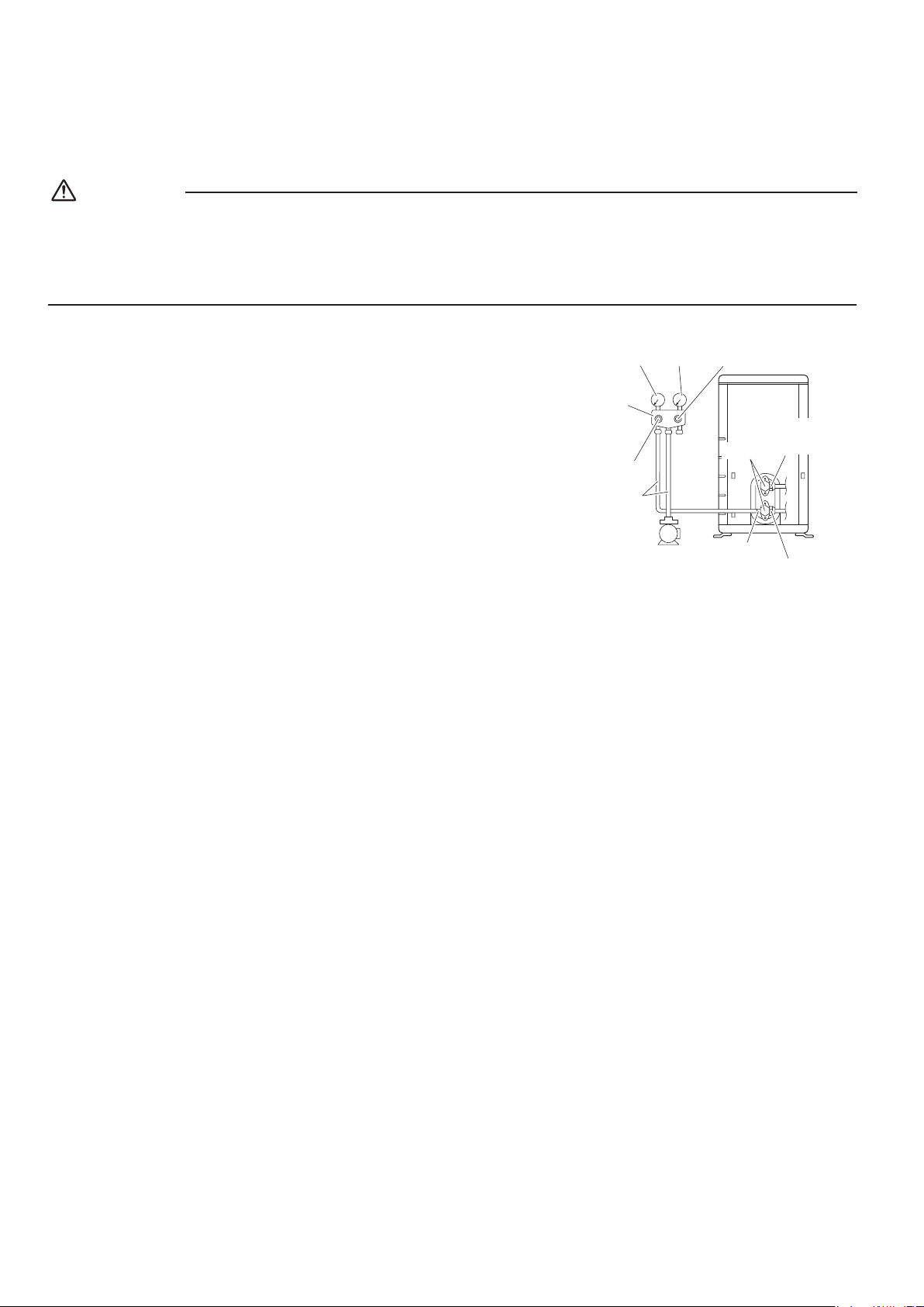
5. Pressure test and evacuating system
WARNING
• Make sure that air or any matter other than refrigerant (R410A) does not get into the refrigeration cycle.
• If refrigerant gas leaks should occur, ventilate the room as soon and as much as possible.
• R410A, as well as other refrigerants, should always be recovered and never be released directly into the environment.
• UseavacuumpumpforR410Aexclusively.Usingthesamevacuumpumpfordifferentrefrigerantsmaydamagethevacuum
pump or the unit.
• When piping work is complete, it is necessary to perform a pressure test
and evacuate system with a vacuum pump.
• If using additional refrigerant, purge the air from the refrigerant pipes and
indoor unit using a vacuum pump, then charge additional refrigerant.
• Useahexagonalwrench(3/16inch(4mm))tooperatethestopvalverod.
• All refrigerant pipe joints should be tightened with a torque wrench to the
speciedtighteningtorque.
Compound
pressure gauge
Pressure
meter
High-pressure
valve
Low-pressure
valve
Vacuum pump
Service port
Liquid
stop
valve
Valve caps
Gas stop valve
Charging
hoses
Gauge
manifold
1) Pressurize the liquid pipe and gas pipe from the service ports of each stop valve to 550psi (3.8MPa) (do not pressurize
more than 550psi (3.8MPa)) for 1 hour minimum, 24 hours recommended. If there is a pressure drop, check for leaks,
make repairs and perform the pressure test again.
2) Connect the gauge manifold's charging hose to the gas stop valve’s service port.
3) Fully open the gauge manifold’s low-pressure valve (Lo) and completely close its high-pressure valve (Hi).
(High-pressure valve will require no further operation.)
4) Evacuatesystemusingvacuumpumptobelow500micronsfor1hourminimum.
5) Close the gauge manifold’s low-pressure valve (Lo) and stop vacuum pump.
(Maintain this condition for 4-5 minutes to make sure that the compound pressure gauge pointer does not swing back.)*
1
6) Remove the valve caps from the liquid stop valve and gas stop valve.
7) Turntheliquidstopvalve’srod90°counter-clockwisewithahexagonalwrenchtoopenthevalve.
Close it after 5 seconds, and check for gas leakage.
Usingsoapywater,checkforgasleakagefromtheindoorunit’sareandoutdoorunit’sareandvalverods.
After the check is complete, wipe all soapy water off.
8) Disconnect the charging hose from the gas stop valve’s service port, then fully open the liquid and gas stop valves.
(Do not attempt to turn the valve rod further than it can go.)
9) Tightenthevalvecapsandserviceportcapsfortheliquidandgasstopvalveswithatorquewrenchtothespecied
torques.
Refer to “4. Refrigerant piping” on page 6 for details.
*
1
If the compound pressure gauge pointer swings back, the refrigerant may have water content or there may be a loose
pipe joint.
Check all pipe joints and retighten nuts as needed, then repeat steps 3) through 5).
01_EN_3P500432-2B.indd 7 10/30/2018 11:53:02 AM
8■English
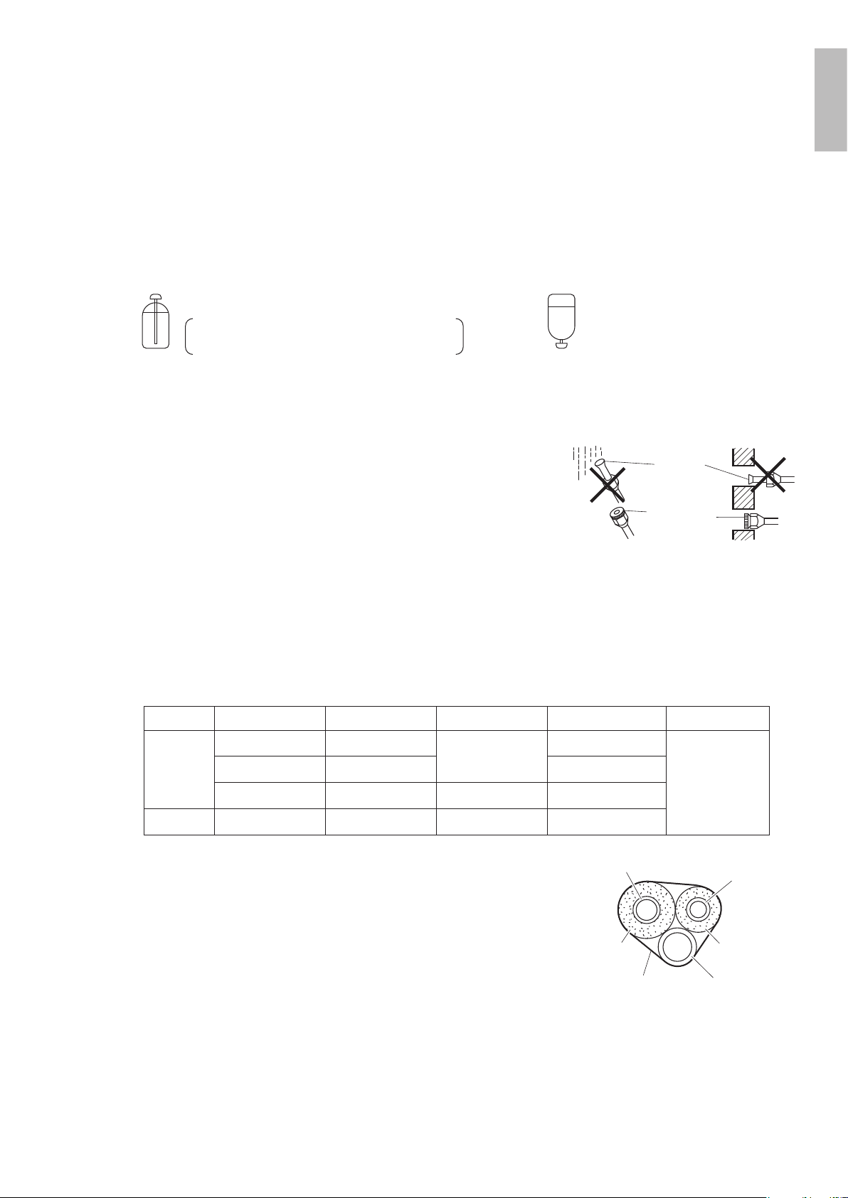
6. Relling refrigerant
Check the type of refrigerant to be used on the machine nameplate.
Precautions when adding R410A
Fill from the liquid pipe in liquid form.
R410Aisamixedrefrigerant,soaddingitingasformmaycausetherefrigerantcompositiontochange,preventingnormal
operation.
1) Beforelling,checkwhetherthecylinderhasasiphonattachedornot.(Itshouldhavesomethinglike“liquidllingsiphon
attached” displayed on it.)
Filling a cylinder with an attached siphon
Stand the cylinder upright when filling.
There is a siphon pipe inside, so the cylinder
need not be upside-down to fill with liquid.
Filling other cylinders
Turn the cylinder
upside-down when filling.
• Be sure to use the R410A tools to ensure pressure and to prevent foreign objects entering.
7. Refrigerant piping work
7-1. Cautions on pipe handling
• Protect the open end of the pipe from dust and moisture.
• All pipe bends should be as gentle as possible. Use a pipe bender for
bending.
7-2. Selection of copper and heat insulation materials
Whenusingcommercialcopperpipesandttings,observethefollowing:
• Insulation material: Polyethylene foam
Heat transfer rate: 0.041 to 0.052W/mK (0.024 to 0.030Btu/fth°F (0.035
to 0.045kcal/mh°C))
Be sure to use insulation that is designed for use with HVAC Systems.
• ACR Copper only.
• Be sure to insulate both the gas and liquid piping and observe the
insulation dimensions as below.
Wall
If no flare cap is
available, cover
the flare mouth
with tape to keep
dirt and water out.
Be sure to
place a cap.
Rain
Gas side
Piping size
O.D. 3/8 inch
(9.5mm)
O.D. 1/2 inch
(12.7mm)
O.D. 5/8 inch
(15.9mm)
O.D. 1/4 inch
(6.4mm)
1-3/16 inch (30mm)
or more
1-9/16 inch (40mm)
or more
1-15/16 inch (50mm)
or more
1-3/16 inch (30mm)
or more
0.031 inch (0.8mm)
(C1220T-O)
0.039 inch (1.0mm)
(C1220T-O)
0.031 inch (0.8mm)
(C1220T-O)
I.D. 15/32-19/32 inch
(12-15mm)
I.D. 9/16-5/8 inch
(14-16mm)
I.D. 5/8-13/16 inch
(16-20mm)
I.D. 5/16-13/32 inch
(8-10mm)
13/32 inch
(10mm) Min.
Minimum bend radius Piping thickness Thermal insulation size
Thermal insulation
thickness
Liquid side
• Use separate thermal insulation pipes for gas and liquid refrigerant pipes.
Gas pipe
Liquid pipe
Gas pipe
insulation
Liquid pipe
insulation
Finishing tape
Drain hose
English
01_EN_3P500432-2B.indd 8 10/30/2018 11:53:02 AM
9 ■English
Wiring
WARNING
• Donotusetappedwires,extensioncords,orstarburstconnections,astheymaycauseoverheating,electricshock,orre.
• Do not use locally purchased electrical parts inside the product. (Do not branch the power for the drain pump, etc., from the
terminalblock.)Doingsomaycauseelectricshockorre.
• The circuit must be protected with safety devices in accordance with local and national codes, i.e. a circuit breaker.
• Use an all-pole disconnection type circuit breaker with at least 1/8 inch (3mm) between the contact point gaps.
• When carrying out wiring, take care not to pull at the conduit.
• Donotconnectthepowerwiretotheindoorunit.Doingsomaycauseelectricshockorre.
• Do not turn on the circuit breaker until all work is completed.
1) Strip the insulation from the wire (3/4 inch (20mm)).
2) Connect the inter-unit wires between the indoor and outdoor units so that the terminal numbers match. Tighten the
terminal screws securely. It is recommended that a slot-head screwdriver be used to tighten the screws.
The screws are packed with the terminal block.
1
2
3
1 2 3
Follow local codes for wiring
and safety devices between
outdoor unit and power
source.
Ground
Firmly fix the wires with
the terminal screws.
Recommend using AWG14, stranded and insulated
wire for connections between indoor and outdoor units.
Local code always supersedes recommendation.
Outdoor unit
Indoor
unit
Power supply
60Hz 208-230V
Firmly fix the
wires with the
terminal screws.
L
1
L
2
Note: Take care to ensure that all wiring between
indoor unit and outdoor unit has a consistent
connection. Any splices can cause communication
errors.
RX09/12/15/18∗
20A
15A
RX24∗
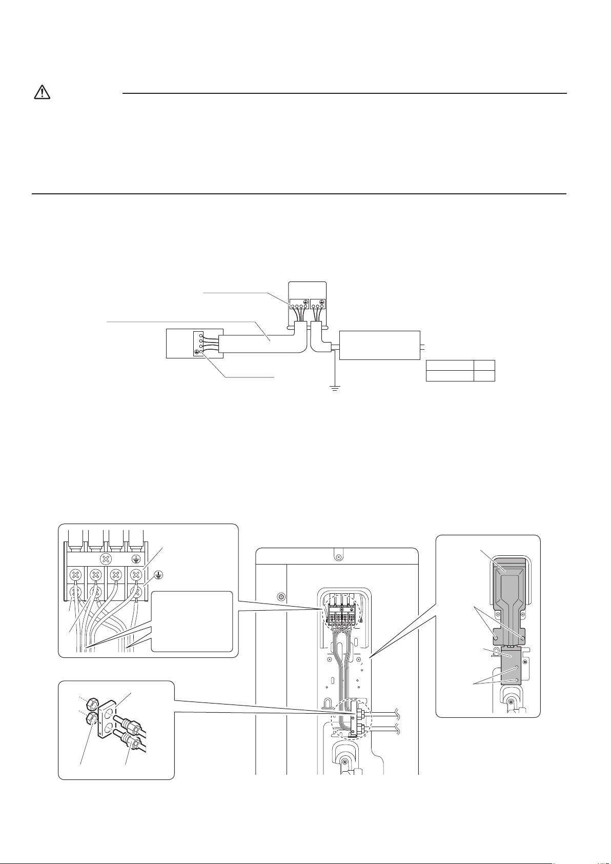
09/12 class
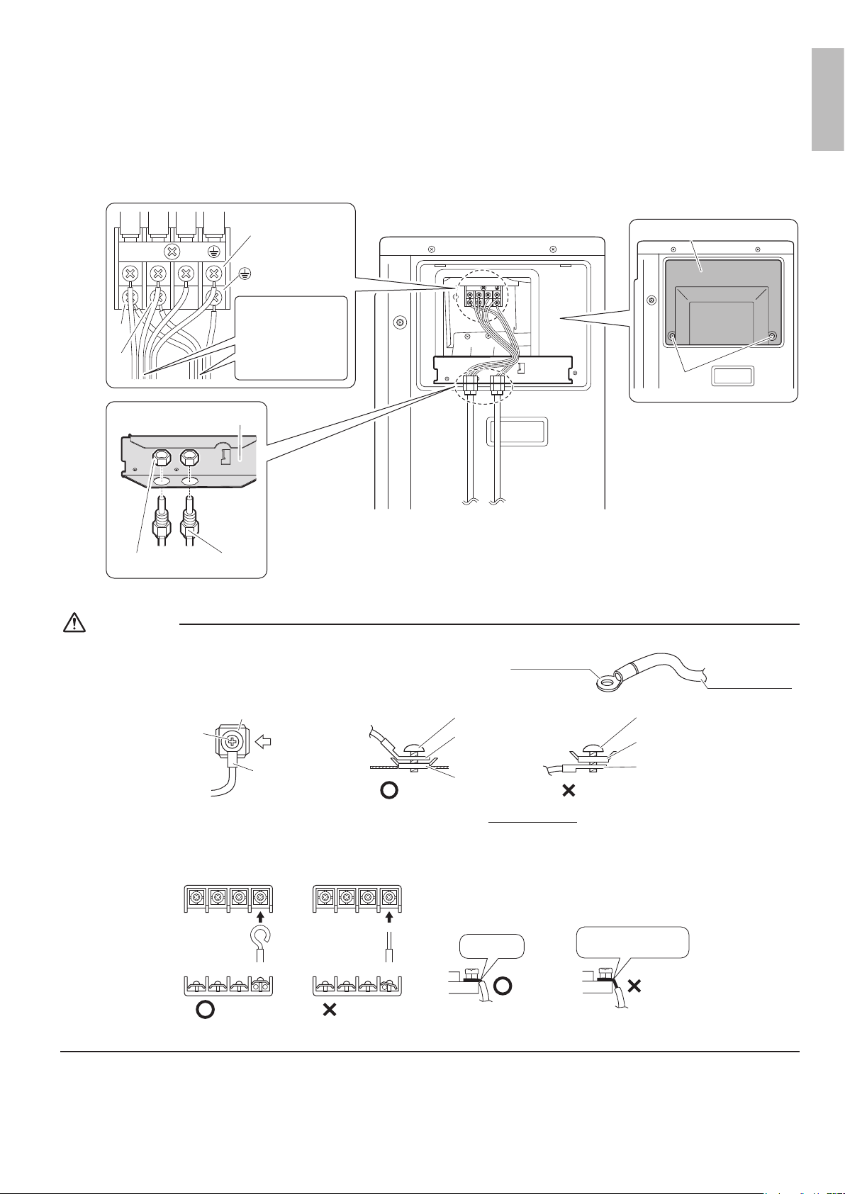
[Method of mounting conduit]
• Aprotectionplateisxedforprotectionfromthehigh-voltagesection.
1) Dismount the stop valve cover by removing the screw.
2) Dismount the protection plate by removing the 2 screws.
3) Dismount the conduit mounting cover by removing the 2 screws.
4) Pass wires through the conduit and secure them with a lock nut.
5) After completing the work, reattach the stop valve cover, the conduit mounting cover, and the protection plate to its
original position.
1
2
3
1
2
3
1
2
3
Screws
Conduit
mounting
cover
Screws
Protection plate
Power supply
terminal block
Shape wires so
that the protection
plate and conduit
mounting plate fit
securely.
Conduit
Lock nut
Conduit
mounting
plate
L
1
L
2
01_EN_3P500432-2B.indd 9 10/30/2018 11:53:03 AM
10■English
15/18/24 class
[Method of mounting conduit]
1) Dismount the service lid by removing the 2 screws.
2) Pass wires through the conduit and secure them with a lock nut.
3) After completing the work, reattach the service lid to its original position.
1
2
3
1
2
3
Power supply
terminal block
Shape wires so
that the protection
plate and conduit
mounting plate fit
securely.
Service lid
Screws
ConduitLock nut
Conduit mounting plate
L
1
L
2
CAUTION
Precautions to be taken for power supply wiring
• When using stranded wires, make sure to use the round crimp-style
terminal for connection to the power supply terminal block.
Stranded wire
Round crimp-style
terminal
Arrow view
Flat washer
Screw
Round
crimp-style
terminal
Good
Round crimp-
style terminal
Flat washer
Screw
Wrong
Flat washer
Round crimp-
style terminal
Screw
A
A
• When connecting the inter-unit wires to the terminal block using a single core wire, be sure to curl the end of the lead.
Improperworkmaycauseheatandres.
Strip wire end
to this point.
Excessive strip length
may cause electric shock
or current leakage.
Stripping wire at terminal block
Good Wrong
Good Wrong
English
01_EN_3P500432-2B.indd 10 10/30/2018 11:53:03 AM
11 ■English
Facility Setting
(cooling at low outdoor temperature)
This function is limited only for facilities (the target of air conditioning is equipment (such as computer)).
Never use it in a residence or ofce (the space where there is a human).
Cutting jumper 6 (J6)onthecircuitboardwillextendtheoperationrangeto14°F(–10°C).Installinganairdirection
adjustmentgrille(soldseparately)willfurtherextendtheoperationrangeto–4°F(–20°C).
In these cases, the unit will
stopoperatingiftheoutdoortemperaturefallsbelow–4°F(–20°C),restartingoncethetemperaturerisesabovethislevel.
1) Remove the top plate of the outdoor unit. (09/12 class: 3 screws, 15/18/24 class: 6 screws)
2) Remove the front plate. (09/12 class: 4 screws, 15/18/24 class: 8 screws)
3) Cut the jumper (J6) of the PCB inside.
CAUTION
• Iftheoutdoorunitisinstalledwheretheheatexchangeroftheunitisexposedtodirectwind,provideawindbreakwall.
• Intermittent noises may be produced by the indoor unit due to the outdoor fan turning on and off when using facility settings.
• Donotplacehumidiersorotheritemswhichmightraisethehumidityinroomswherefacilitysettingsarebeingused.
Ahumidiermightcausedewjumpingfromtheindoorunitoutletvent.
• Cutting jumper 6 (J6) sets the indoor fan tap to the highest position. Notify the user about this.
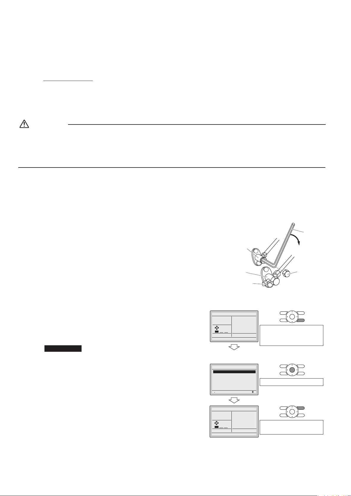
Pump Down Operation
In order to protect the environment, be sure to pump down when relocating or disposing of the unit.
1) Remove the valve cap from the liquid stop valve and gas stop valve.
2) Carry out forced cooling operation.
3) After5to10minutes,closetheliquidstopvalvewithahexagonalwrench.
4) After 2 to 3 minutes, close the gas stop valve and stop forced cooling operation.
5) Attach the valve cap once procedures are complete.
Gas
stop valve
Valve cap
Hexagonal
wrench
Close
Liquid
stop valve
Service port
Forced cooling operation
[For FFQ and FDMQ models]
Using the indoor unit’s remote controller
[For wired remote controller]
1) Set to COOL operation using the remote controller.
2) PressandholdtheCancelbuttonfor4secondsorlonger.
Service settings menu is displayed.
3) Select Test Operation in the service settings menu, and press
the Menu/OK button. Basic screen returns and “Test Operation” is
displayed at the bottom.
4) PresstheOn/Offbuttonwithin10seconds,andtheforcedcooling
operation starts.
• Forced cooling operation will stop automatically after about 15
minutes. To stop the operation, press the On/Off button.
Basic screen
1)
2)
Cool
Return Clean the filter
Set to
Cool
68F
Press and hold the Cancel
button for 4 seconds or
longer during backlight lit.
Service Settings
menu screen
3)
Setting
1/3
Service Settings
Test Operation
Maintenance Contact
Field Settings
Energy Saving Options
Prohibit Buttons
Min Setpoints Differential
Press the Menu/OK button.
4)
Set temperature
80°F
Cool
Test Operation
Press the On/Off button
(within 10 seconds).
01_EN_3P500432-2B.indd 11 10/30/2018 11:53:03 AM
12■English
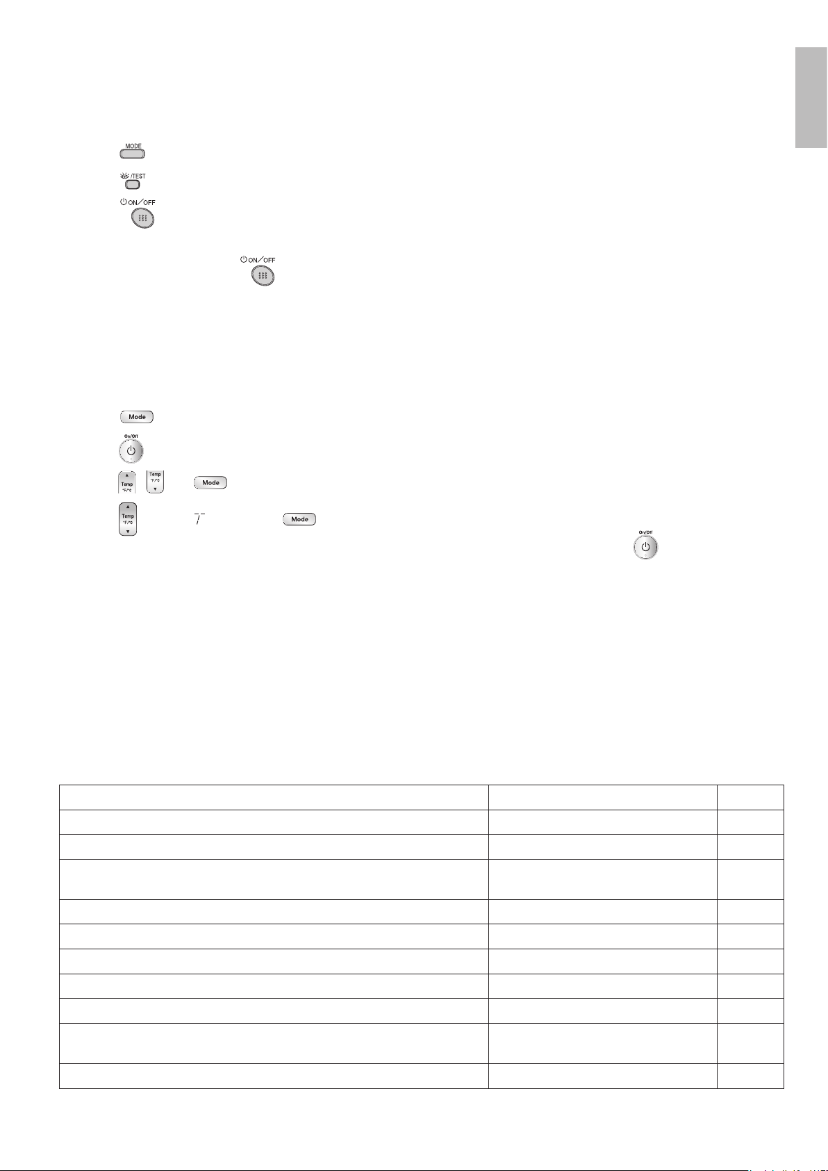
[For wireless remote controller]
1) Press
and select the COOL operation.
2) Press
twice. “Test” is displayed.
3) Press
within 10 seconds, and the forced cooling operation starts.
• Forced cooling operation will stop automatically after about 15 minutes.
To stop the operation, press
.
[For FTXR models]
Using the indoor unit ON/OFF switch
Press the indoor unit ON/OFF switch for at least 5 seconds. (The operation will start.)
• Forced cooling operation will stop automatically after about 15 minutes.
To stop the operation, press the indoor unit ON/OFF switch.
Using the indoor unit’s remote controller
1) Press
and select the COOL operation.
2) Press
to turn on the system.
3) Press
, and at the same time.
4) Press
, select “ ”, and press forconrmation.
• Forced cooling operation will stop automatically after about 30 minutes. To stop the operation, press
.
Trial Operation and
Testing
1. Trial operation and testing
Refer to the installation manual for the indoor unit.
2. Test items
Test items Symptom Check
Indoor and outdoor units are installed properly on solid bases. Fall, vibration, noise
No refrigerant gas leaks. Incomplete cooling/heating function
Refrigerantgasandliquidpipesandindoordrainhoseextensionare
thermally insulated.
Water leakage
Draining line is properly installed. Water leakage
System is properly grounded. Electricalleakage
Thespeciedwiresareusedforinter-unitwiring. No operation or burn damage
Indoor or outdoor unit’s air inlet or air outlet are unobstructed. Incomplete cooling/heating function
Stop valves are opened. Incomplete cooling/heating function
Check that the connector of the lead wires of the decoration panel is
connected securely.
Louvers do not move
Indoor unit properly receives wireless remote control commands. No operation
English
01_EN_3P500432-2B.indd 12 10/30/2018 11:53:04 AM

Two-dimensional bar code
is a manufacturing code.
3P500432-2B
M17B180B
(1810)
HT
00_CV_3P500432-2B.indd 2 10/30/2018 11:15:19 AM