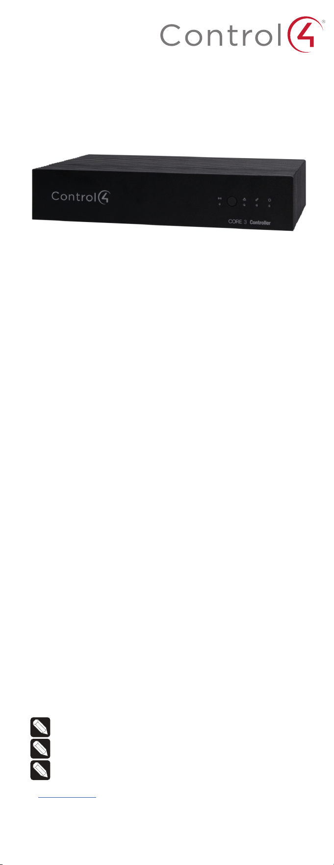
Control4 CORE 3 Controller
Installation Guide
Supported model
• C4-CORE3 Control4 CORE 3 Hub & Controller
Introduction
Designed for an exceptional multi-room entertainment experience, the Control4®
CORE 3 Controller is the perfect fusion of high resolution audio and smart automation for
those small to mid-sized projects.
The CORE 3 delivers a beautiful, intuitive, and responsive on-screen user interface with
the ability to create and enhance the entertainment experience for any TV in the house.
The CORE 3 can orchestrate a wide range of entertainment devices including Blu-ray
players, satellite or cable boxes, game consoles, TVs, and virtually any product with
infrared (IR) or serial (RS-232) control. It also features IP control for Apple TV, Roku,
televisions, AVRs, or other network-connected devices, as well as smart automation
control utilizing contact, relay, and secure wireless Zigbee and Z-Wave control for lights,
thermostats, smart locks, and more
For entertainment, the CORE 3 also includes a built-in music server that allows you to
listen to your own music library, stream from a variety of leading music services, or from
your AirPlay-enabled devices using Control4 ShairBridge technology.
Box contents
The following items are included in the CORE 3 controller box:
• CORE 3 controller
• AC power cord
• IR emitters (3)
• Rack ears (2)
• Rubber feet (2)
• External antennas (2, 1 for Zigbee and 1 for Z-Wave)
• Terminal block for contact and relay
Accessories available for purchase
• CORE 3 Wall-Mount Bracket (C4-CORE3-WM)
• Control4 3-Meter Wireless Antenna Kit (C4-AK-3M)
• Control4 Dual-Band Wi-Fi USB Adapter (C4-USBWIFI OR C4-USBWIFI-1)
• Control4 3.5 mm to DB9 Serial Cable (C4-CBL3.5-DB9B)
Requirements and specifications
Note: We recommend using Ethernet instead of Wi-Fi for the best network
connectivity.
Note: The Ethernet or Wi-Fi network should be installed before starting the
CORE 3 controller installation.
Note: The CORE 3 requires OS 3.3 or newer.
Composer Pro software is required to configure this device. See the Composer Pro User
Guide (ctrl4.co/cpro-ug) for details.
Warnings
Caution! To reduce the risk of electrical shock, do not expose this apparatus to
rain or moisture.
AVERTISSEMENT ! Pour réduire le risque de choc électrique, n’exposez pas cet
appareil à la pluie ou à l’humidité.
Caution! In an over-current condition on USB, the software disables the
output. If the attached USB device does not appear to power on, remove the
USB device from the controller.
AVERTISSEMENT ! Dans une condition de surintensité sur USB ou sortie de
contact le logiciel désactive sortie. Si le périphérique USB ou le capteur
de contact connecté ne semble pas s’allumer, retirez le périphérique du
contrôleur.
Specifications
Inputs / Outputs
Video out
1 video out—1 HDMI
Video
HDMI 2.0a; 3840x2160 @ 60Hz (4K); HDCP 2.2 and HDCP
1.4
Audio out
4 audio out—1 HDMI, 2 × 3.5 mm stereo audio, 1 digital coax
Digital signal processing
Digital coax in—Input level
Audio Out 1/2 (analog)—Balance, volume, loudness,
6-band PEQ, mono/stereo, test signal, mute
Digital coax out—Volume, mute
Audio playback formats
AAC, AIFF, ALAC, FLAC, M4A, MP2, MP3, MP4/M4A, Ogg
Vorbis, PCM, WAV, WMA
Audio in
1 audio in—1 digital coax audio in
High-resolution audio playback
Up to 192 kHz / 24 bit
Network
Ethernet
2 10/100/1000BaseT compatible ports—1 PoE+ in and
1 switch network port
Wi-Fi
Optional Dual-Band Wi-Fi USB Adapter
(2.4 GHz, 5 Ghz, 802.11ac/b/g/n/a)
Zigbee Pro
802.15.4
Zigbee antenna
External reverse SMA connector
Z-Wave
Z-Wave 700 series
Z-Wave antenna
External reverse SMA connector
USB port
1 USB 3.0 port—500mA
Control
IR out
6 IR out—5V 27mA max output
IR capture
1 IR receiver—front, 20-60 KHz
Serial out
3 serial out (shared with IR out 1-3)
Contact input
1 × 2-30V DC input, 12V DC 125mA max output
Relay
1 × relay ouput—AC: 36V, 2A max across relay; DC: 24V, 2A
max across relay
Power
Power requirements
100-240 VAC, 60/50Hz or PoE+
Power consumption
Max: 18W, 61 BTUs/hour
Idle: 12W, 41 BTUs/hour
Other
Operating temperature
32˚F ~ 104˚F (0˚C ~ 40˚C)
Storage temperature
4˚F ~ 158˚F (-20˚C ~ 70˚C)
Dimensions (H × W × D)
1.68 × 8.63 × 5.5” (42.9 × 220 × 140 mm)
Weight
2.1 lb (0.95 kg)
Shipping weight
3.5 lb (1.6 kg)
Additional resources
The following resources are available for more support.
• Control4 CORE series help and information: ctrl4.co/core
• Snap One Tech Community and Knowledgebase: tech.control4.com
• Control4 Technical Support: ctrl4.co/techsupport
• Control4 website: www.control4.com
• Ethernet—To connect using an Ethernet connection, connect the network cable
into the controller’s RJ-45 port (labeled ENET/POE+ IN) and into the network port
on the wall or at the network switch.
• Wi-Fi—To connect using Wi-Fi, first connect the unit to Ethernet, connect the
Wi-Fi adapter to the USB port, and then use Composer Pro System Manager to
reconfigure the unit for Wi-Fi.
5 Connect system devices. Attach IR and serial devices as described in “Connecting
the IR ports/serial ports” and “Setting up IR emitters.”
6 Set up any external storage devices as described in “Setting up external storage
devices” in this document.
7 If using AC power, connect the power cord to the controller’s power port and then
into an electrical outlet.
Connecting the IR ports/serial ports (optional)
The controller provides six IR ports, and ports 1, 2, and 3 can be reconfigured
independently for serial communication. If not used for serial, they can be used for IR.
Connect a serial device to the controller using the Control4 3.5 mm-to-DB9 Serial Cable
(C4-CBL3.5-DB9B, sold separately).
1 The serial ports support baud rates between 1200 to 115200 baud for odd and even
parity. The serial ports do not support hardware flow control.
2 See Knowledgebase article #268 (ctrl4.co/contr-serial-pinout) for pinout diagrams.
3 To configure a port for serial or IR, make the appropriate connections in your
project using Composer Pro. See the Composer Pro User Guide for details.
Note: The serial ports can be configured as straight-through or null with
Composer Pro. Serial ports by default are configured straight-through and
can be changed in Composer by selecting Null Modem Enabled (SERIAL 1, 2,
or 3).
Setting up IR emitters
Your system may contain third-party products that are controlled through IR commands.
1 Connect one of the included IR emitters to an IR OUT port on the controller.
2 Place the stick-on emitter end onto the IR receiver on the Blu-ray player, TV, or other
target device to emit IR signals from the controller to the target device.
Setting up external storage devices (optional)
You can store and access media from an external storage device, for example, a network
hard drive or USB memory device, by connecting the USB drive to the USB port and
configuring or scanning the media in Composer Pro.
Note: We support only externally powered USB drives or solid state USB sticks.
Self-powered USB drives are not supported.
Note: When using USB storage devices on an CORE 3 controller, you can use
only one partition with a 2 TB maximum size. This limitation also applies to the
USB storage on other controllers.
Composer Pro driver information
Use Auto Discovery and SDDP to add the driver to the Composer project. See the
Composer Pro User Guide (ctrl4.co/cpro-ug) for details.
OvrC setup and configuration
OvrC gives you remote device management, real-time notifications, and intuitive
customer management, right from your computer or mobile device. Setup is
plug-and-play, with no port forwarding or DDNS address required.
To add this device to your OvrC account:
1 Connect CORE 3 controller to the Internet.
2 Navigate to OvrC (www.ovrc.com) and log in to your account.
3 Add the device (MAC address and Service Tag numbers needed for authentication).
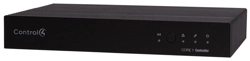
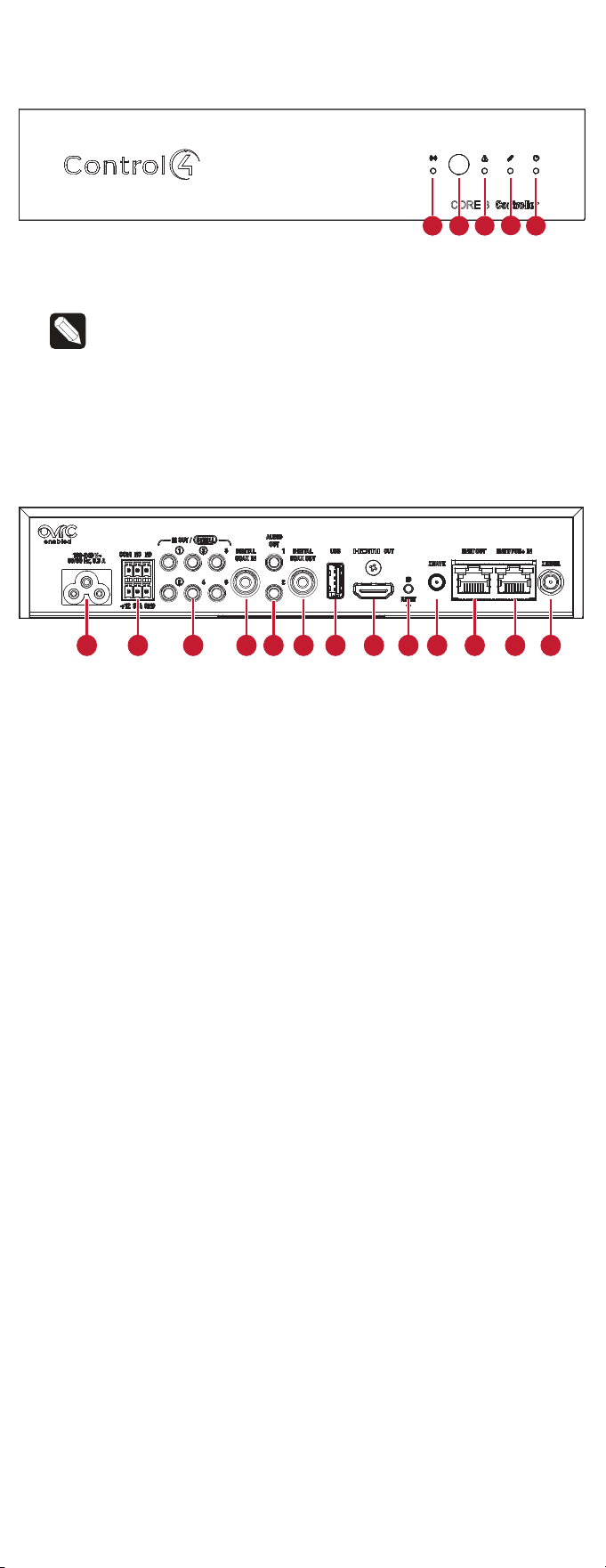
Front view
A Activity LED—The Activity LED shows when the controller is streaming audio.
B IR window—IR receiver for learning IR codes.
C Caution LED—This LED shows solid red, then blinks blue during the boot process.
Note: The Caution LED blinks orange during the factory restore process. See
“Reset to factory settings” in this document.
D Link LED—The LED indicates that the controller has been identified in a Control4
project and is communicating with Director.
E Power LED—The blue LED indicates that AC power is present. The controller turns on
immediately after power is applied to it.
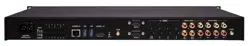
Back view
A Power port—AC power connector for an IEC 60320-C5 power cord.
B Contact and relay— Connect one relay device and one contact sensor device to the
terminal block connector. Relay connections are COM, NC (normally closed), and NO
(normally open). Contact sensor connections are +12, SIG (signal), and GND (ground).
C IR OUT/SERIAL—3.5 mm jacks for up to six IR emitters or for a combination of IR
emitters and serial devices. Ports 1, 2, and 3 can be configured independently
for serial control (for controlling receivers or disc changers) or for IR control. See
“Connecting the IR ports/serial ports” in this document for more information.
D DIGITAL COAX IN—Allows audio to be shared over the local network to other Control4
devices.
E AUDIO OUT 1/2—Outputs audio shared from other Control4 devices or from digital
audio sources (local media or digital streaming services).
F DIGITAL COAX OUT—Outputs audio shared from other Control4 devices or from
digital audio sources (local media or digital streaming services such).
G USB—One port for an external USB drive (such as a USB stick formatted FAT32). See
“Setting up external storage devices” in this document.
H HDMI OUT—An HDMI port to display navigation menus. Also an audio out over HDMI.
I ID button and RESET—ID button is pressed to identify the device in Composer Pro. The
ID button on the CORE 3 is also an LED that displays feedback useful during a factory
restore. The RESET pinhole is used to reset or factory restore the controller.
J ZWAVE—Antenna connector for the Z-Wave radio.
K ENET OUT—RJ-45 jack for Ethernet out connection. Acts as a 2-port network switch
with ENET/POE+ IN jack.
L ENET/POE+ IN—RJ-45 jack for a 10/100/1000BaseT Ethernet connection. Also can
power the controller with PoE+.
M ZIGBEE—Antenna connector for the Zigbee radio.
Installation instructions
To install the controller:
1 Ensure that the home network is in place before starting system setup. An Ethernet
connection to the local network is required for setup. The controller requires a
network connection to use all of the features as designed. After initial configuration,
Ethernet (recommended) or Wi-Fi can be used to connect the controller to web-
based media databases, communicate with other IP devices in the home, and
access Control4 system updates.
2 Mount the controller near the local devices you need to control. The controller
can be hidden behind a TV, mounted on a wall, installed in a rack, or placed on
a shelf. The CORE 3 Wall-Mount Bracket is sold separately and designed for easy
installation of the CORE 3 controller behind a TV or on the wall.
3 Attach antennas to the ZIGBEE and ZWAVE antenna connectors.
4 Connect the controller to the network.
A
CB
D
E
E
A B C D G H I J K L MF
Control4 CORE 3 Controller
Installation Guide
Supported model
• C4-CORE3 Control4 CORE 3 Hub & Controller
Introduction
Designed for an exceptional multi-room entertainment experience, the Control4®
CORE 3 Controller is the perfect fusion of high resolution audio and smart automation for
those small to mid-sized projects.
The CORE 3 delivers a beautiful, intuitive, and responsive on-screen user interface with
the ability to create and enhance the entertainment experience for any TV in the house.
The CORE 3 can orchestrate a wide range of entertainment devices including Blu-ray
players, satellite or cable boxes, game consoles, TVs, and virtually any product with
infrared (IR) or serial (RS-232) control. It also features IP control for Apple TV, Roku,
televisions, AVRs, or other network-connected devices, as well as smart automation
control utilizing contact, relay, and secure wireless Zigbee and Z-Wave control for lights,
thermostats, smart locks, and more
For entertainment, the CORE 3 also includes a built-in music server that allows you to
listen to your own music library, stream from a variety of leading music services, or from
your AirPlay-enabled devices using Control4 ShairBridge technology.
Box contents
The following items are included in the CORE 3 controller box:
• CORE 3 controller
• AC power cord
• IR emitters (3)
• Rack ears (2)
• Rubber feet (2)
• External antennas (2, 1 for Zigbee and 1 for Z-Wave)
• Terminal block for contact and relay
Accessories available for purchase
• CORE 3 Wall-Mount Bracket (C4-CORE3-WM)
• Control4 3-Meter Wireless Antenna Kit (C4-AK-3M)
• Control4 Dual-Band Wi-Fi USB Adapter (C4-USBWIFI OR C4-USBWIFI-1)
• Control4 3.5 mm to DB9 Serial Cable (C4-CBL3.5-DB9B)
Requirements and specifications
Note: We recommend using Ethernet instead of Wi-Fi for the best network
connectivity.
Note: The Ethernet or Wi-Fi network should be installed before starting the
CORE 3 controller installation.
Note: The CORE 3 requires OS 3.3 or newer.
Composer Pro software is required to configure this device. See the Composer Pro User
Guide (ctrl4.co/cpro-ug) for details.
Warnings
Caution! To reduce the risk of electrical shock, do not expose this apparatus to
rain or moisture.
AVERTISSEMENT ! Pour réduire le risque de choc électrique, n’exposez pas cet
appareil à la pluie ou à l’humidité.
Caution! In an over-current condition on USB, the software disables the
output. If the attached USB device does not appear to power on, remove the
USB device from the controller.
AVERTISSEMENT ! Dans une condition de surintensité sur USB ou sortie de
contact le logiciel désactive sortie. Si le périphérique USB ou le capteur
de contact connecté ne semble pas s’allumer, retirez le périphérique du
contrôleur.
Specifications
Inputs / Outputs
Video out
1 video out—1 HDMI
Video
HDMI 2.0a; 3840x2160 @ 60Hz (4K); HDCP 2.2 and HDCP
1.4
Audio out
4 audio out—1 HDMI, 2 × 3.5 mm stereo audio, 1 digital coax
Digital signal processing
Digital coax in—Input level
Audio Out 1/2 (analog)—Balance, volume, loudness,
6-band PEQ, mono/stereo, test signal, mute
Digital coax out—Volume, mute
Audio playback formats
AAC, AIFF, ALAC, FLAC, M4A, MP2, MP3, MP4/M4A, Ogg
Vorbis, PCM, WAV, WMA
Audio in
1 audio in—1 digital coax audio in
High-resolution audio playback
Up to 192 kHz / 24 bit
Network
Ethernet
2 10/100/1000BaseT compatible ports—1 PoE+ in and
1 switch network port
Wi-Fi
Optional Dual-Band Wi-Fi USB Adapter
(2.4 GHz, 5 Ghz, 802.11ac/b/g/n/a)
Zigbee Pro
802.15.4
Zigbee antenna
External reverse SMA connector
Z-Wave
Z-Wave 700 series
Z-Wave antenna
External reverse SMA connector
USB port
1 USB 3.0 port—500mA
Control
IR out
6 IR out—5V 27mA max output
IR capture
1 IR receiver—front, 20-60 KHz
Serial out
3 serial out (shared with IR out 1-3)
Contact input
1 × 2-30V DC input, 12V DC 125mA max output
Relay
1 × relay ouput—AC: 36V, 2A max across relay; DC: 24V, 2A
max across relay
Power
Power requirements
100-240 VAC, 60/50Hz or PoE+
Power consumption
Max: 18W, 61 BTUs/hour
Idle: 12W, 41 BTUs/hour
Other
Operating temperature
32˚F ~ 104˚F (0˚C ~ 40˚C)
Storage temperature
4˚F ~ 158˚F (-20˚C ~ 70˚C)
Dimensions (H × W × D)
1.68 × 8.63 × 5.5” (42.9 × 220 × 140 mm)
Weight
2.1 lb (0.95 kg)
Shipping weight
3.5 lb (1.6 kg)
Additional resources
The following resources are available for more support.
• Control4 CORE series help and information: ctrl4.co/core
• Snap One Tech Community and Knowledgebase: tech.control4.com
• Control4 Technical Support: ctrl4.co/techsupport
• Control4 website: www.control4.com
• Ethernet—To connect using an Ethernet connection, connect the network cable
into the controller’s RJ-45 port (labeled ENET/POE+ IN) and into the network port
on the wall or at the network switch.
• Wi-Fi—To connect using Wi-Fi, first connect the unit to Ethernet, connect the
Wi-Fi adapter to the USB port, and then use Composer Pro System Manager to
reconfigure the unit for Wi-Fi.
5 Connect system devices. Attach IR and serial devices as described in “Connecting
the IR ports/serial ports” and “Setting up IR emitters.”
6 Set up any external storage devices as described in “Setting up external storage
devices” in this document.
7 If using AC power, connect the power cord to the controller’s power port and then
into an electrical outlet.
Connecting the IR ports/serial ports (optional)
The controller provides six IR ports, and ports 1, 2, and 3 can be reconfigured
independently for serial communication. If not used for serial, they can be used for IR.
Connect a serial device to the controller using the Control4 3.5 mm-to-DB9 Serial Cable
(C4-CBL3.5-DB9B, sold separately).
1 The serial ports support baud rates between 1200 to 115200 baud for odd and even
parity. The serial ports do not support hardware flow control.
2 See Knowledgebase article #268 (ctrl4.co/contr-serial-pinout) for pinout diagrams.
3 To configure a port for serial or IR, make the appropriate connections in your
project using Composer Pro. See the Composer Pro User Guide for details.
Note: The serial ports can be configured as straight-through or null with
Composer Pro. Serial ports by default are configured straight-through and
can be changed in Composer by selecting Null Modem Enabled (SERIAL 1, 2,
or 3).
Setting up IR emitters
Your system may contain third-party products that are controlled through IR commands.
1 Connect one of the included IR emitters to an IR OUT port on the controller.
2 Place the stick-on emitter end onto the IR receiver on the Blu-ray player, TV, or other
target device to emit IR signals from the controller to the target device.
Setting up external storage devices (optional)
You can store and access media from an external storage device, for example, a network
hard drive or USB memory device, by connecting the USB drive to the USB port and
configuring or scanning the media in Composer Pro.
Note: We support only externally powered USB drives or solid state USB sticks.
Self-powered USB drives are not supported.
Note: When using USB storage devices on an CORE 3 controller, you can use
only one partition with a 2 TB maximum size. This limitation also applies to the
USB storage on other controllers.
Composer Pro driver information
Use Auto Discovery and SDDP to add the driver to the Composer project. See the
Composer Pro User Guide (ctrl4.co/cpro-ug) for details.
OvrC setup and configuration
OvrC gives you remote device management, real-time notifications, and intuitive
customer management, right from your computer or mobile device. Setup is
plug-and-play, with no port forwarding or DDNS address required.
To add this device to your OvrC account:
1 Connect CORE 3 controller to the Internet.
2 Navigate to OvrC (www.ovrc.com) and log in to your account.
3 Add the device (MAC address and Service Tag numbers needed for authentication).
Front view
A Activity LED—The Activity LED shows when the controller is streaming audio.
B IR window—IR receiver for learning IR codes.
C Caution LED—This LED shows solid red, then blinks blue during the boot process.
Note: The Caution LED blinks orange during the factory restore process. See
“Reset to factory settings” in this document.
D Link LED—The LED indicates that the controller has been identified in a Control4
project and is communicating with Director.
E Power LED—The blue LED indicates that AC power is present. The controller turns on
immediately after power is applied to it.
Back view
A Power port—AC power connector for an IEC 60320-C5 power cord.
B Contact and relay— Connect one relay device and one contact sensor device to the
terminal block connector. Relay connections are COM, NC (normally closed), and NO
(normally open). Contact sensor connections are +12, SIG (signal), and GND (ground).
C IR OUT/SERIAL—3.5 mm jacks for up to six IR emitters or for a combination of IR
emitters and serial devices. Ports 1, 2, and 3 can be configured independently
for serial control (for controlling receivers or disc changers) or for IR control. See
“Connecting the IR ports/serial ports” in this document for more information.
D DIGITAL COAX IN—Allows audio to be shared over the local network to other Control4
devices.
E AUDIO OUT 1/2—Outputs audio shared from other Control4 devices or from digital
audio sources (local media or digital streaming services).
F DIGITAL COAX OUT—Outputs audio shared from other Control4 devices or from
digital audio sources (local media or digital streaming services such).
G USB—One port for an external USB drive (such as a USB stick formatted FAT32). See
“Setting up external storage devices” in this document.
H HDMI OUT—An HDMI port to display navigation menus. Also an audio out over HDMI.
I ID button and RESET—ID button is pressed to identify the device in Composer Pro. The
ID button on the CORE 3 is also an LED that displays feedback useful during a factory
restore. The RESET pinhole is used to reset or factory restore the controller.
J ZWAVE—Antenna connector for the Z-Wave radio.
K ENET OUT—RJ-45 jack for Ethernet out connection. Acts as a 2-port network switch
with ENET/POE+ IN jack.
L ENET/POE+ IN—RJ-45 jack for a 10/100/1000BaseT Ethernet connection. Also can
power the controller with PoE+.
M ZIGBEE—Antenna connector for the Zigbee radio.
Installation instructions
To install the controller:
1 Ensure that the home network is in place before starting system setup. An Ethernet
connection to the local network is required for setup. The controller requires a
network connection to use all of the features as designed. After initial configuration,
Ethernet (recommended) or Wi-Fi can be used to connect the controller to web-
based media databases, communicate with other IP devices in the home, and
access Control4 system updates.
2 Mount the controller near the local devices you need to control. The controller
can be hidden behind a TV, mounted on a wall, installed in a rack, or placed on
a shelf. The CORE 3 Wall-Mount Bracket is sold separately and designed for easy
installation of the CORE 3 controller behind a TV or on the wall.
3 Attach antennas to the ZIGBEE and ZWAVE antenna connectors.
4 Connect the controller to the network.
A
CB
D
E
E
A B C D G H I J K L MF

Copyright 2022, Snap One, LLC. All rights reserved. Snap One and its respective logos are
registered trademarks or trademarks of Snap One, LLC (formerly known as Wirepath Home
Systems, LLC), in the United States and/or other countries. 4Store, 4Sight, Control4, Control4 My
Home, SnapAV, Mockupancy, NEEO, OvrC, Wirepath, and Wirepath ONE are also registered
trademarks or trademarks of Snap One, LLC. Other names and brands may be claimed as the
property of their respective owners. Snap One makes no claim that the information contained
herein covers all installation scenarios and contingencies, or product use risks. Information
within this specification subject to change without notice.
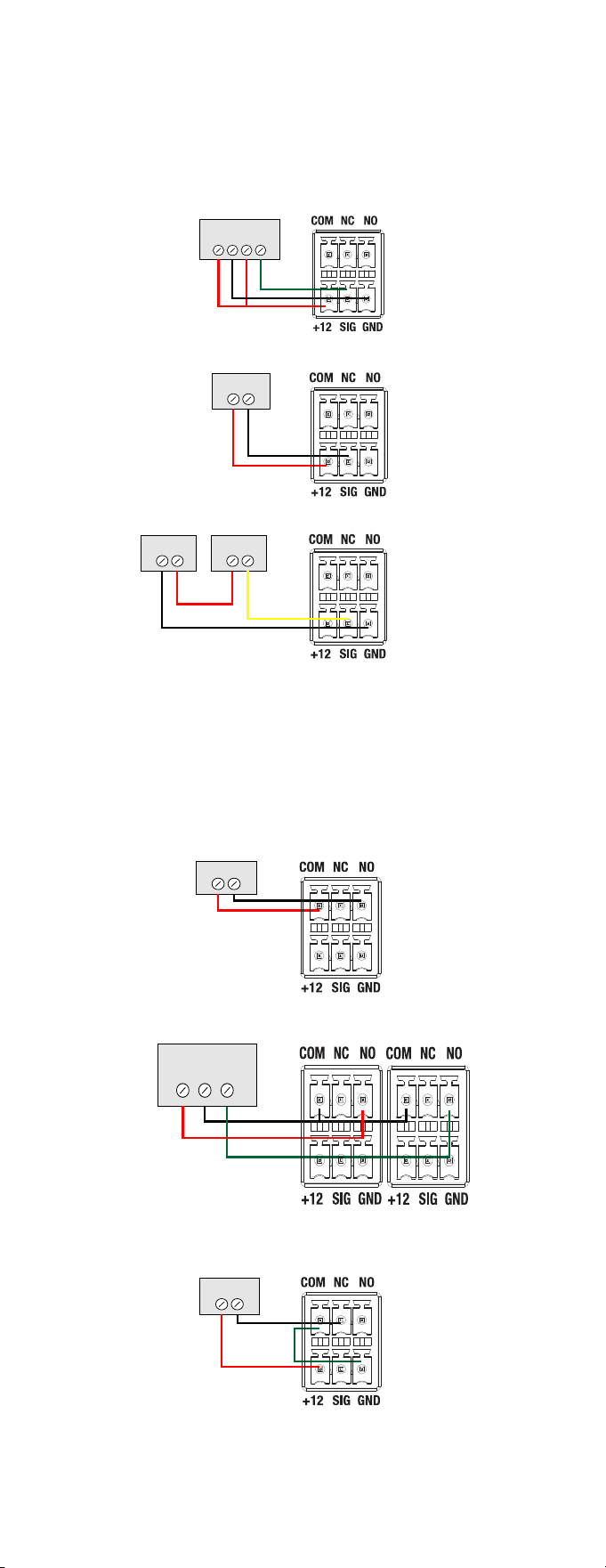
Connecting the contact port
The CORE 3 provides one contact port on the included pluggable terminal
block (+12, SIG, GRD). See the examples below to learn how to connect various
devices to the contact port.
Wire the contact to a sensor that also needs power (Motion sensor)
Wire the contact to a dry contact sensor (Door contact sensor)
Wire the contact to an externally powered sensor (Driveway sensor)
Connecting the relay port
The CORE 3 provides one relay port on the included pluggable terminal block.
See the examples below to learn now to connect various devices to the relay
port.
Wire the relay to a single-relay device, normally open (Fireplace)
Wire the relay to a dual-relay device (Blinds)
Wire the relay with power from the contact, normally closed (Amplifier trigger)
Motion Sensor
+12V 0V COM NO
Dry Contact
Driveway
Sensor
External
12V Power
Fireplace
Dual-Relay Blind
UP COM DOWN
Relay 1
Relay 2
12V Trigger
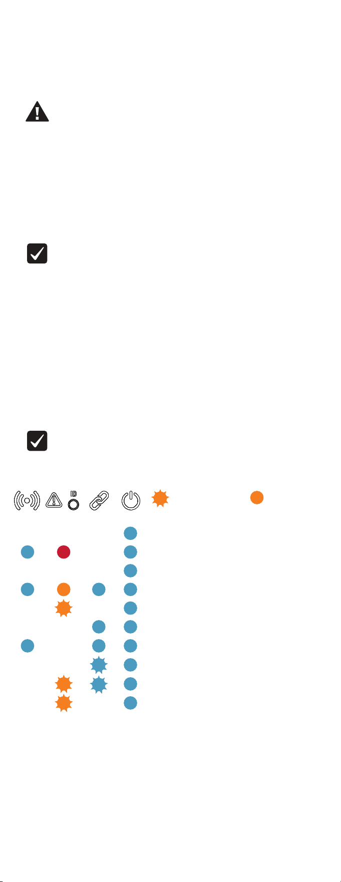
Troubleshooting
Reset to factory settings
Caution! The factory restore process will remove the Composer project.
To restore the controller to the factory default image:
1 Insert one end of a paper clip into the small hole on the back of the controller
labeled RESET.
2 Press and hold the RESET button. The controller resets and the ID button changes
to solid red.
3 Hold the button until the ID flashes double orange. This should take five to seven
seconds. The ID button flashes orange while the factory restore is running. When
complete, the ID button turns o and the device power cycles one more time to
complete the factory restore process.
Note: During the reset process, the ID button provides the same feedback as
the Caution LED on the front of the controller.
Power cycle the controller
1 Press and hold the ID button for five seconds. The controller turns o and back on.
Reset the network settings
To reset the controller network settings to the default:
1 Disconnect power to the controller.
2 While pressing and holding the ID button on the back of the controller, power on the
controller.
3 Hold the ID button until ID button turns solid orange and the Link and Power LEDs
are solid blue, and then immediately release the button.
Note: During the reset process, the ID button provides the same feedback as
the Caution LED on the front of the controller.
LED status information
Just powered on
Boot started
Boot complete
Network reset check
Factory restore underway
Connected to Director
Playing audio
Updating
Update error
No IP address
Activity Caution Link Power
—Flashing LED —Solid LED
200-00725-A
2022-05-31 DH
A
Pluggable terminal block connectors
For the contact and relay ports, the CORE 3 makes use of pluggable terminal
block connectors which are removable plastic parts that locks in individual
wires (included).
To connect a device to the pluggable terminal block:
1 Insert one of the wires required for your device into the appropriate
opening in the pluggable terminal block you reserved for that device.
2 Use a small flat-blade screwdriver to tighten the screw and secure the
wire in the terminal block.
Example: To add a motion sensor (see Figure 3), connect its wires
to the following contact openings:
• Power input to +12V
• Output signal to SIG
• Ground connector to GND
Note: To connect dry contact closure devices, such as doorbells,
connect the switch between +12 (power) and SIG (signal).
control4.com | 888.400.4070
More help
For the latest version of this document and to view additional materials, open the URL
below or scan the QR code on a device that can view PDFs.
Legal, Warranty, and Regulatory/Safety information
Visit snapone.com/legal for details.
MOST RECENT VERSION
ctrl4.co/core3-ig
MORE INFO ON CORE CONTROLLERS
ctrl4.co/core
Copyright 2022, Snap One, LLC. All rights reserved. Snap One and its respective logos are
registered trademarks or trademarks of Snap One, LLC (formerly known as Wirepath Home
Systems, LLC), in the United States and/or other countries. 4Store, 4Sight, Control4, Control4 My
Home, SnapAV, Mockupancy, NEEO, OvrC, Wirepath, and Wirepath ONE are also registered
trademarks or trademarks of Snap One, LLC. Other names and brands may be claimed as the
property of their respective owners. Snap One makes no claim that the information contained
herein covers all installation scenarios and contingencies, or product use risks. Information
within this specification subject to change without notice.
Connecting the contact port
The CORE 3 provides one contact port on the included pluggable terminal
block (+12, SIG, GRD). See the examples below to learn how to connect various
devices to the contact port.
Wire the contact to a sensor that also needs power (Motion sensor)
Wire the contact to a dry contact sensor (Door contact sensor)
Wire the contact to an externally powered sensor (Driveway sensor)
Connecting the relay port
The CORE 3 provides one relay port on the included pluggable terminal block.
See the examples below to learn now to connect various devices to the relay
port.
Wire the relay to a single-relay device, normally open (Fireplace)
Wire the relay to a dual-relay device (Blinds)
Wire the relay with power from the contact, normally closed (Amplifier trigger)
Motion Sensor
+12V 0V COM NO
Dry Contact
Driveway
Sensor
External
12V Power
Fireplace
Dual-Relay Blind
UP COM DOWN
Relay 1
Relay 2
12V Trigger
Troubleshooting
Reset to factory settings
Caution! The factory restore process will remove the Composer project.
To restore the controller to the factory default image:
1 Insert one end of a paper clip into the small hole on the back of the controller
labeled RESET.
2 Press and hold the RESET button. The controller resets and the ID button changes
to solid red.
3 Hold the button until the ID flashes double orange. This should take five to seven
seconds. The ID button flashes orange while the factory restore is running. When
complete, the ID button turns o and the device power cycles one more time to
complete the factory restore process.
Note: During the reset process, the ID button provides the same feedback as
the Caution LED on the front of the controller.
Power cycle the controller
1 Press and hold the ID button for five seconds. The controller turns o and back on.
Reset the network settings
To reset the controller network settings to the default:
1 Disconnect power to the controller.
2 While pressing and holding the ID button on the back of the controller, power on the
controller.
3 Hold the ID button until ID button turns solid orange and the Link and Power LEDs
are solid blue, and then immediately release the button.
Note: During the reset process, the ID button provides the same feedback as
the Caution LED on the front of the controller.
LED status information
Just powered on
Boot started
Boot complete
Network reset check
Factory restore underway
Connected to Director
Playing audio
Updating
Update error
No IP address
Activity Caution Link Power
—Flashing LED —Solid LED
200-00725-A
2022-05-31 DH
A
Pluggable terminal block connectors
For the contact and relay ports, the CORE 3 makes use of pluggable terminal
block connectors which are removable plastic parts that locks in individual
wires (included).
To connect a device to the pluggable terminal block:
1 Insert one of the wires required for your device into the appropriate
opening in the pluggable terminal block you reserved for that device.
2 Use a small flat-blade screwdriver to tighten the screw and secure the
wire in the terminal block.
Example: To add a motion sensor (see Figure 3), connect its wires
to the following contact openings:
• Power input to +12V
• Output signal to SIG
• Ground connector to GND
Note: To connect dry contact closure devices, such as doorbells,
connect the switch between +12 (power) and SIG (signal).
control4.com | 888.400.4070
More help
For the latest version of this document and to view additional materials, open the URL
below or scan the QR code on a device that can view PDFs.
Legal, Warranty, and Regulatory/Safety information
Visit snapone.com/legal for details.
MOST RECENT VERSION
ctrl4.co/core3-ig
MORE INFO ON CORE CONTROLLERS
ctrl4.co/core