Loading ...
Loading ...
Loading ...
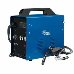
6. ASSEMBLING THE
WELDER
Make sure the power supply information on the
machine’s rating plate is compatible with the power
supply you intend to connect it to.
Stock nos.63669 & 70051.
These appliances are supplied with an approved plug
and cable for your safety.
A suitable plug must be fitted by a qualified
electrician.
Stock No.70050.
This appliance power wiring has insulation stripped in
preparation for wiring a 16A plug (not supplied).
It is designed for connection to a 16amp power supply
rated at 230V AC.
Because these appliances are constructed mostly of
metal parts, they are Class 1 machines; meaning, they
must have an earth connection in the power supply. This
is to prevent electrocution in the event of a failure.
Note: Remove the plug from the socket before carrying
out adjustment, servicing or maintenance.
Check that the electrical supply delivers the voltage and
frequency corresponding to the welding machine and
that it is fitted with a delayed fuse suited to the maximum
delivered rated current.
Note: The welding machines are set to the highest
voltage at the factory.
7. SETTING THE WELDER
7.1 GENERAL
This medium weight, portable welder requires no
special lifting instructions, however, it contains
dedicated circuitry and must be handled with care.
The welder is designed to weld with a filler wire feed
through the torch (MIG).
7.2 LOCATION
Locate the machine close to the correct power supply
and allow a 500mm air gap around to ensure sufficient
ventilation. There are two cooling fans located in the rear
of the machine housing which must be kept clear.
Equally, ensure no debris can be drawn into the
machine.
Make certain the location does not pose any hazards as
detailed in the safety instructions, before attempting to
start the machine.
Note: Refer to the rating label for energy input details.
Warning! Remove the plug from the socket before
carrying out adjustment, servicing or maintenance.
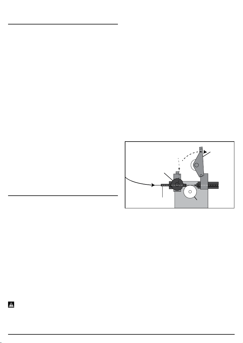
7.3 INSTALLING THE FILLER WIRE
– FIGS. 1 - 3
The welding machine is designed to accept the standard
size drums of wire (0.45kg).
The welding wire is flux-cored types this provides a
means of shielding the weld pool from the atmosphere.
Do not let the filler wire become uncoiled or tangled as
this will lead to problems with delivery to the welding
torch.
Select the filler wire suitable for the parent metal and
with a gauge to match the welder specification.
Note: If the welding machine is not regularly used,
remove the wire which is prone to rust and will cause
feed problems next time.
1. Open the top panel.
2. Unscrew the large plastic ring. Sit the reel on to the
hub (10). Refit the large plastic ring.
3. Fit the wire spool so that it feeds off the base of the
reel towards the wire drive unit (11).
4. Pull tensioner (11.1) forward off the tension arm
(11.2), the tension arm (11.2) will spring up out of the
way.
1
FIG.
(11.2)
(11.1)
(11.3)
(11.4)
5. The wire must sit in the appropriate groove for the
wire gauge. The groove size is etched on the side of
the roller. Remove nut to see the groove size that is
NOT in use. The drive roller (11.4) can be removed
from shaft, to change the groove size for appropriate
wire gauge. Unscrew and remove the retaining cap.
6. Pass the filler wire through the guide (11.3) and over
the top of the drive roller, make sure the wire is well
inside the torch liner before closing the arm (11.2)
and tensioner (11.1).
–
7
–
Loading ...
Loading ...
Loading ...