RSR - ELECTRIC
15 TRAY
ROTATING SINGLE RACK
BAKERY OVENS

ROTORBAKE Series Ovens - electric version - Page 2
C
ONTENTS
Declaration of Conformity 4
General Warning 6
Shipment 7
Unloading and moving 8
Checking 8
Storage and Out of Service 9
Dismantling 10
Technical specifications and identifying information 11,12,13
Electrical Specifications 14
Water connection 14
Local 15
Placement 16
Exploded Oven divided into two parts 17
Assembly oven divided into two parts 18
Electrical Connection 19
Water and Drainage Connection 20
Steam exhaust pipe 21
Air flow regulator 22
Start-up 23
Instructions for the User 24
Rotary rack 25
Operating Instructions 26
Control Panel - Extra digital model 27
Extra digital model operation 28
Control Panel10 programs Electronic model 31
10 programs Electronic model operation 32
Control Panel 100 programs Electronic model 35
100 programs Electronic model operation 36
Shutting off the oven 48
Cleaning and Care 49
Breakdown measures 49
Extended down-time measures 49
Annual maintenance 50
Maintenance gear motor 51
Malfunctions and causes 52
Requesting service 53
Spare parts order form 54
Spare parts water plan 55
Spare parts complete door 56
List of complete door spare parts 57
Spare parts motors and fan group 58
List of motors and fan spare parts 59
Spare parts automatic lift group 60
List of spare parts automatic lift group 61
Spare parts standard lift group 62

ROTORBAKE Series Ovens - electric version - Page 3
List of standard lift group spare parts 63
Spare parts lamp group 64
Legend of symbols 65
Digital control extra model electrical lay out 66
Digital control extra model electrical diagram
FROM
67
TO
71
10 Programs electronic model lay out 72
10 Programs electronic model electrical diagram
FROM
73
TO
76
100 Programs electronic model lay out 77
100 Programs electronic model electrical diagram
FROM
78
TO
81
Accessories 82
Notes 83

ROTORBAKE Series Ovens - electric version - Page 6
This manual must be delivered along with the equipment and accompany it throughout
its entire life span.
These instructions must be kept close to the equipment and in an easily accessible
place, to always allow convenient consultation.
Only qualified personnel may install, start and service the oven in compliance with
these manufacturer instructions and according to current regulations for each
instance.
No safety or other devices must be moved, removed, deactivated or interrupted as
this would void the manufacturer’s warranty
Qualified personnel should subject the equipment to maintenance from the
manufacturer at the scheduled intervals.
The oven must be used solely for the purpose for which it was designed, built and
protected, thus to bake all types of bread and bakery products having a maximum size
and weight compatible with the baking pans and chambers. Any other use shall be
deemed improper.
It is not recommended for use in baking products having high alcohol content.
Only properly trained personnel must use the oven.
The baking chamber and entire oven must be cleaned daily, not only to preserve its
appearance but also to ensure hygiene and proper functioning.
All connections (electrical power supply, gas and water supply for models that include
the latter) must be disconnected when the oven is not in use.
Deactivate the equipment in the event of a malfunction or breakdown.
Non-original spare parts cannot ensure the smooth functioning and safety of the oven.
Therefore, you may be certain that the manufacturer or the manufacturer itself of the
necessary quality only if you contact personnel authorizes both spare parts and
labour.
For versions with humidifier: For better operation and a longer oven life, the
manufacturer recommends including a water softener between the water mains and
the oven.
ROTORBAKE Series Ovens - electric version - Page 7
S
HIPMENT
T
RANSPORT
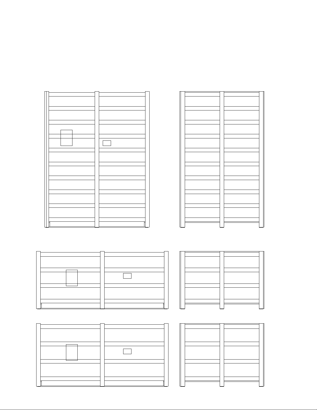
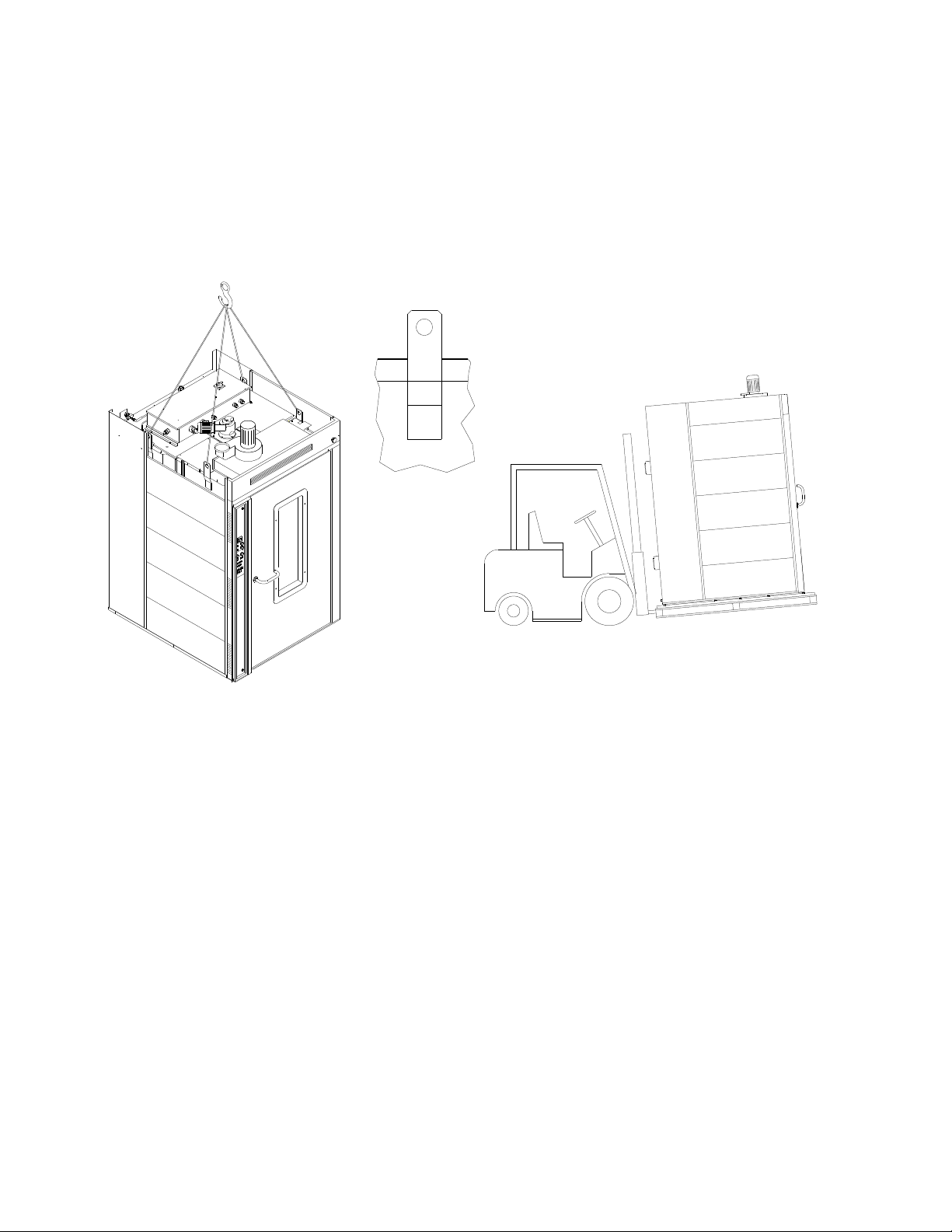
The oven in normally supplied packed in an open-top wooden cage resting on a pallet skid.
The individual parts are protected and placed inside the oven.
Packing and warning position
Side
Front
Address
Packing and warning position oven disassembled for closed container
Address
Address
ROTORBAKE Series Ovens - electric version - Page 8
U
NLOADING AND MOVING
The oven must be unloaded by means of a forklift, and moved internally by the same
means or via pallet changer when the oven is still resting on the skid.
Upon receipt, before unpacking, check whether the packing appears to be damaged: if so,
accept the goods with reservations and provide photographic evidence of any obvious
damage.
C
HECKING
Check all parts of the oven after unpacking in search of any damage.
If shipping damage is found, follow the supply contract for the necessary steps in order to
receive insurance coverage.

ROTORBAKE Series Ovens - electric version - Page 9
S
TORAGE AND
O
UT OF
S
ERVICE
S
TORAGE
The machine, as it is supplied, cannot be stacked on other ovens or on other goods without
providing adequate support or suitable covering to prevent damage of any kind.
The temperature in the place of storage should be between -10°C and 70°C; climatic conditions as
regards humidity must never be such as to cause condensation.
In general, the oven has a degree of protection equivalent to IP44.
O
UT OF SERVICE
When the machine is not in use for an extended period as in the case of summer holidays,
extraordinary maintenance, etc., proceed as follows:
- Disconnect the power and water supplies.
- Open the oven door slightly to allow some air to circulate inside and avoid the formation of
mould inside the oven. In providing the opening as described above, it may be advisable to install
a screen to keep mice out, with openings no larger than 5 mm.
ROTORBAKE Series Ovens - electric version - Page 10
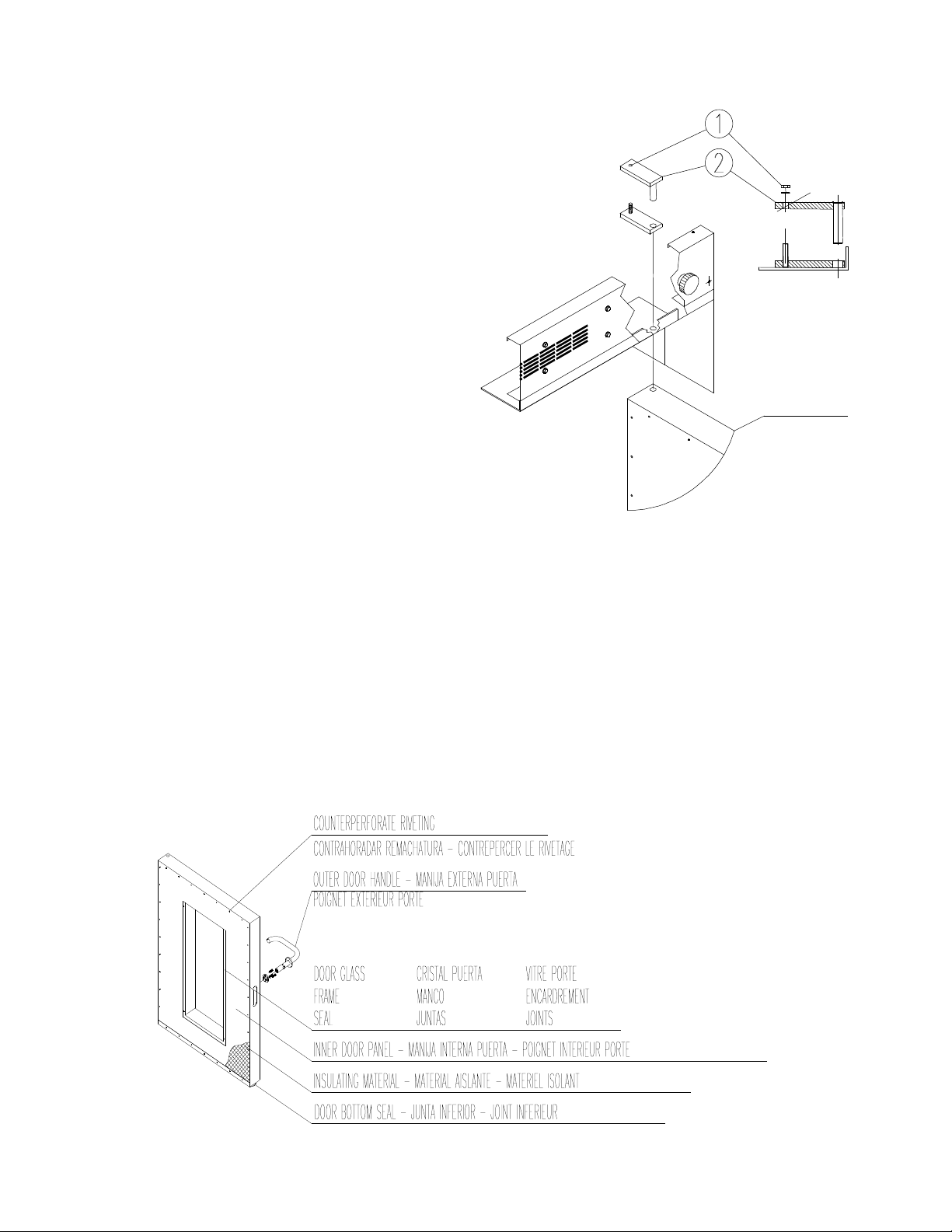
D
ISMANTLING
When the machine is stopped for demolition,
proceed as follows:
- The power water supply must be
completely disconnected by qualified
personnel.
- A company that is authorized for the disposal of
waste materials must perform demolition of the
oven. The company will carry out the procedure
of dismantling it, separating the materials
according to type and provide for their delivery to
their final destination.
-The insulating material contained in the wall
space inside the machine and in the access door
must be collected in sturdy plastic bags and
stored in special waste disposal facilities
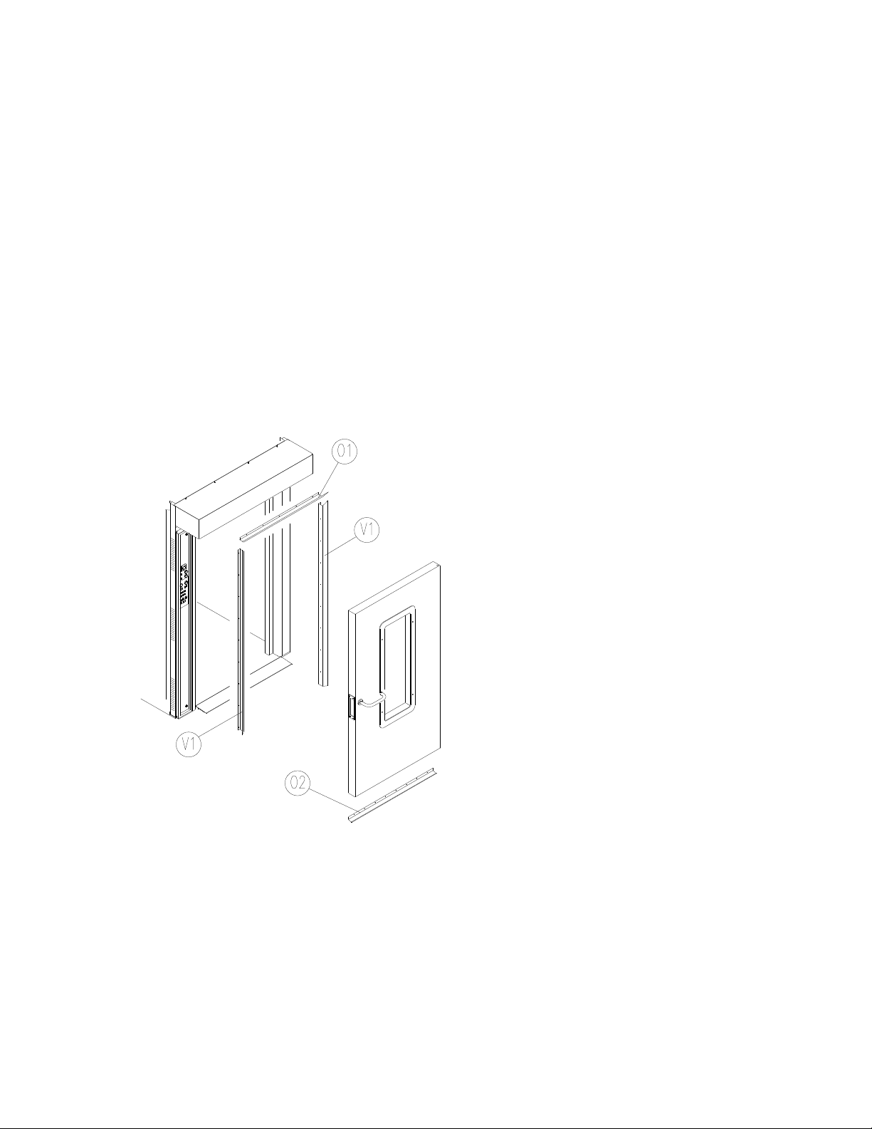
- To remove the door from its housing, unscrew
the bolt 1 and remove the plate 2.
- Unscrew the inside; remove the lower gasket; detach the frames and remove the gasket and glass
from the door.
- Detach the inside panel of the door and remove the insulating material.
The insulating material in the wall spaces of the machine may irritate the skin and
respiratory tract on contact.
We recommend wearing protective clothing including a mask and gloves.
DOOR

ROTORBAKE Series Ovens - electric version - Page 11
The essential technical specifications of the equipment are listed on the serial plate, and all
connections are marked on the oven as shown in the drawing below.
The model, ID and serial number must be indicated on all correspondence with the
manufacturer or service centre.
Serial Plate
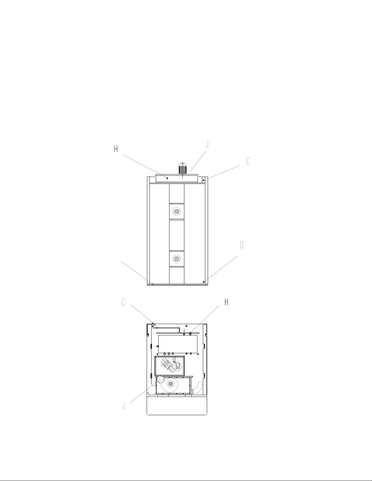
ROTORBAKE Series Ovens - electric version - Page 12
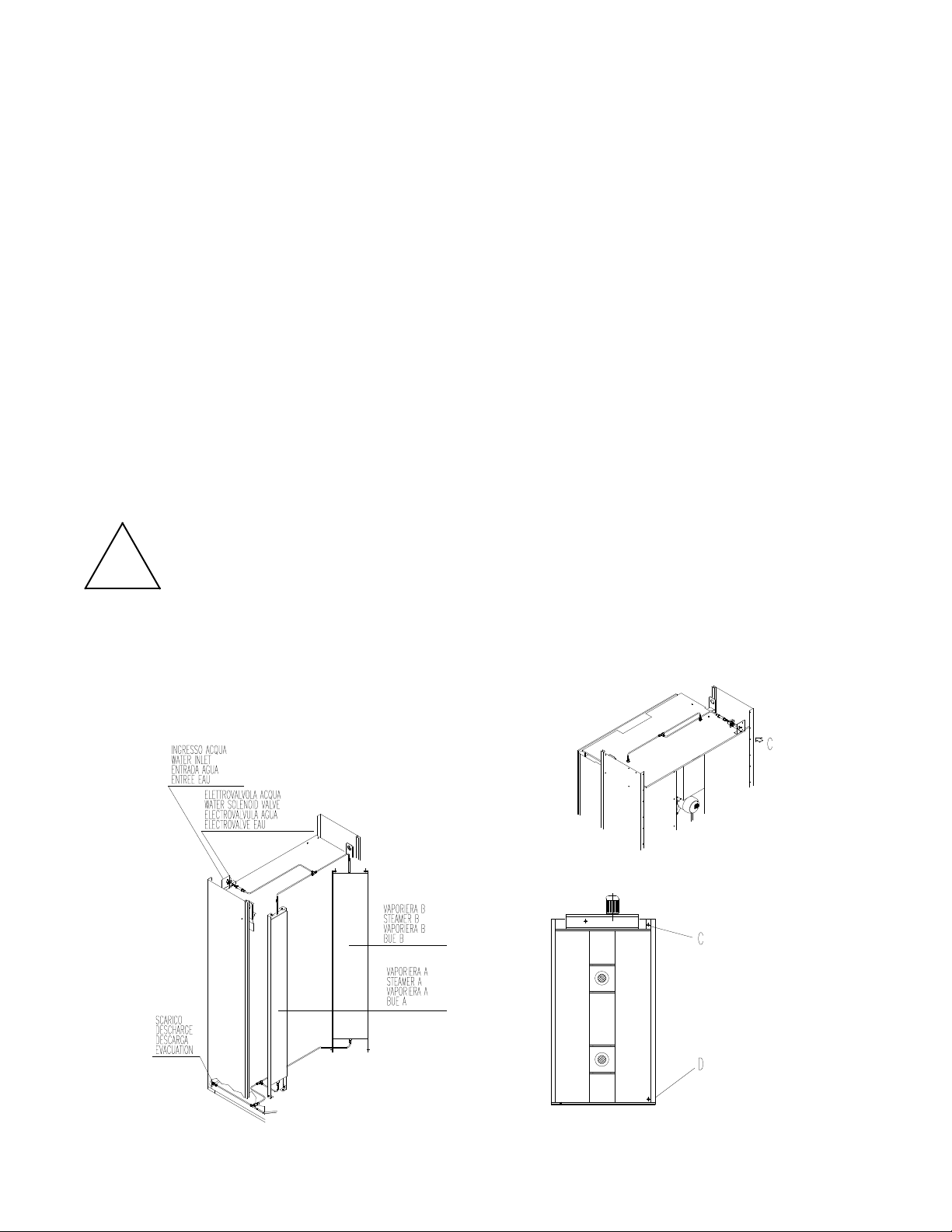
Layout of connections
C - Water inlet (¾”)
D -Water outlet (
1
/
2
”)
G - Equipotent terminal
H - Power cord inlet
J - Steam outlet
ROTORBAKE Series Ovens - electric version - Page 13
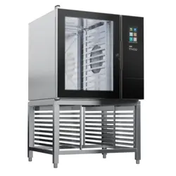
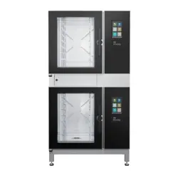
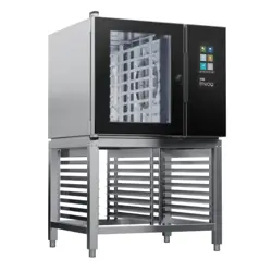
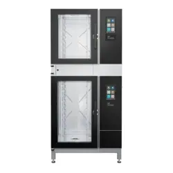
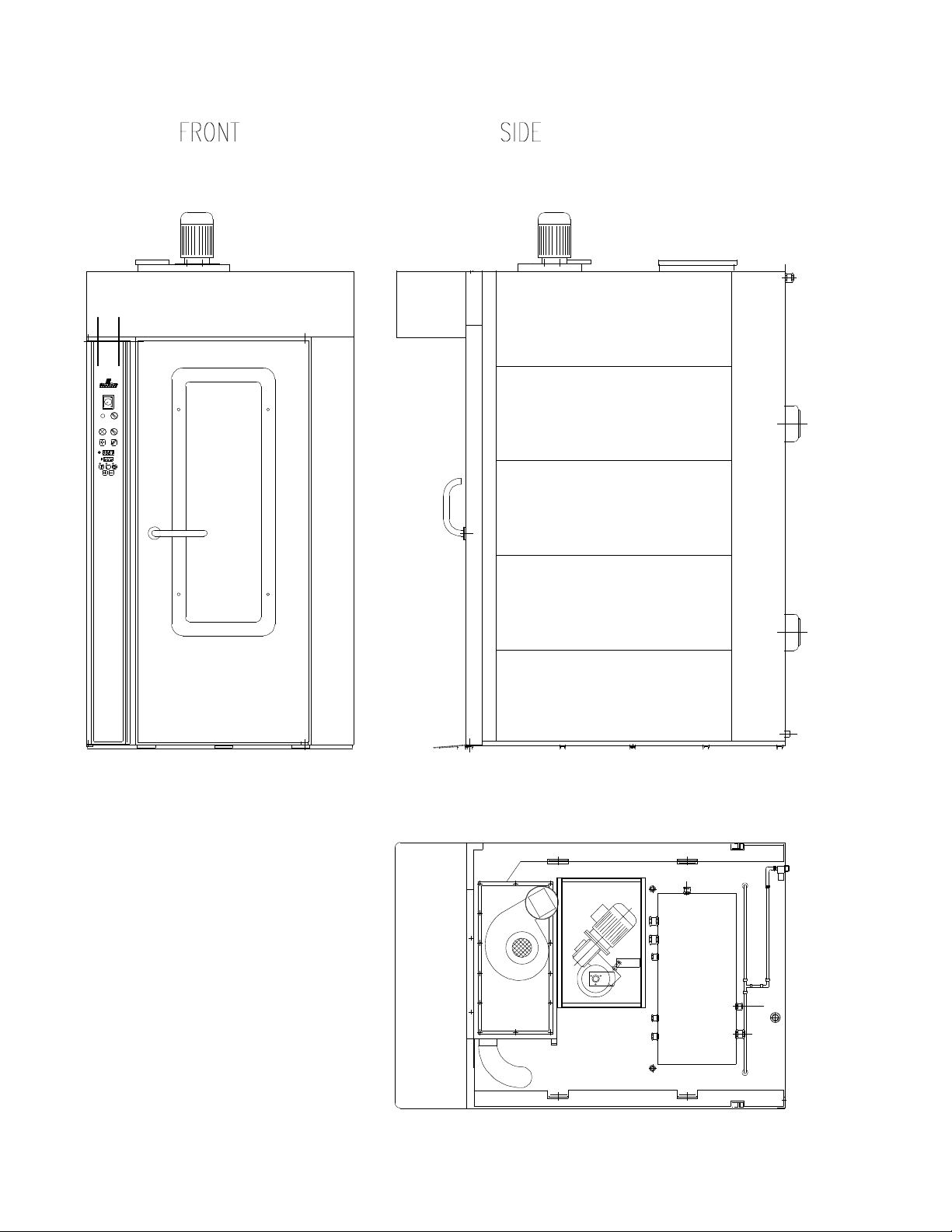
View of the equipments

ROTORBAKE Series Ovens - electric version - Page 14
Model
Rated voltage
ACV
Power cord
min. type H07 RN-F
minimum size
Rated voltage
kW
RotorBake E5 230 3 V
AC
50 H
Z
4x35 mm² 24
400 3N V
AC
50 H
Z
5x10 mm²
We recommend softened water with a hardness of 5°f. If the mains pressure does not fall
within the range indicated below, a pressure reducer must be installed upstream from the
oven.
Model Water drainage
fitting
Water inlet
fitting
Mains pressure
RotorBake E5
1/2
“
¾ “ 50 - 300 kPa
ROTORBAKE Series Ovens - electric version - Page 15
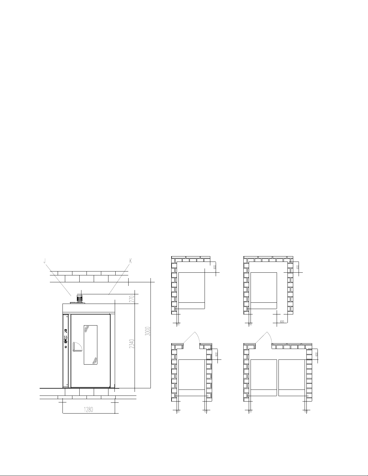
L
OCAL
The equipment must be positioned in a well-ventilated place, preferably under a ventilation
hood to ensure rapid evacuation of cooking fumes. Observe the free areas required by
current regulations for both the supply of combustion air and evacuation of any gas leaks.
The room temperature of the installation site must not fall below +5° C or rise above +40°
C; the air humidity must be between 40% and 75%. Other environmental conditions could
negatively affect equipment operation.
The oven has adjustable feet for leveling. Turning the feet as needed must eliminate any
unevenness of the floor or support surface. Check using a level or baking pan containing a
small amount of water.
There must be at least 10 cm between the back and walls of the oven and other equipment
or flammable walls. If these distances are reduced, or the oven is installed next to other
heating equipment (e.g., fryers), take special precautions such as radiation protection.
However, the manufacturer recommends a distance of 50 cm for convenient cleaning and
maintenance.
Make sure the equipment openings are not blocked or covered!
Fire regulations must be strictly observed and upheld.

ROTORBAKE Series Ovens - electric version - Page 16
!
!
Caution!
The following restrictions, technical rules and Directives must be observed and
complied with during placement and installation:
- Current legal restrictions;
- Regional building and fire codes;
- Accident-prevention regulations;
- Directives and instructions by the electrical power utility company;
- curent CEI instructions;
- Building directives on fireproofing technique requirements for ventilation systems;
- Any special local restrictions;
- Workplace restrictions;
- Kitchen safety rules;
- Ministry of the Interior Memo 68 dated 25.11.1959 and subsequent amendments
“Safety rules for mains-powered thermal systems”;
- Current regulations for flues and connections;
- Directives on kitchen ventilation systems.
Remove any protective film from the outer panels of the oven by peeling it off slowly,
making sure to remove any traces of glue. These may be removed using suitable products
such as stain-removal benzene.
ROTORBAKE Series Ovens - electric version - Page 17
E
XPLODED
O
VEN DIVIDED INTO TWO PARTS
ROTORBAKE Series Ovens - electric version - Page 18
A
SSEMBLY
O
VEN DIVIDED INTO TWO PARTS
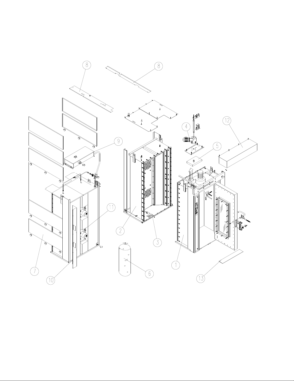
Remove all the material stowed inside the oven and make sure all the parts are in good
conditions.
Position the two parts“1 - 2” in vertical and lay a bead of high temperature sealing
compound “3” around the perimeter surface of both parts.
Position part “1” “2” together and all nuts and bolts and tighten.
Insert the first lateral side panel “7” and move it in the low position (make sure both central
locating bolts on top are aligned).
Fill the wall space in the oven structure with the insulating material contained in the bags
“6” starting from the bottom upwards, taking care to press it, to make it uniformly compact.
Repeat it and install the last panel “7” at the top.
Repeat it in the other side of the oven.
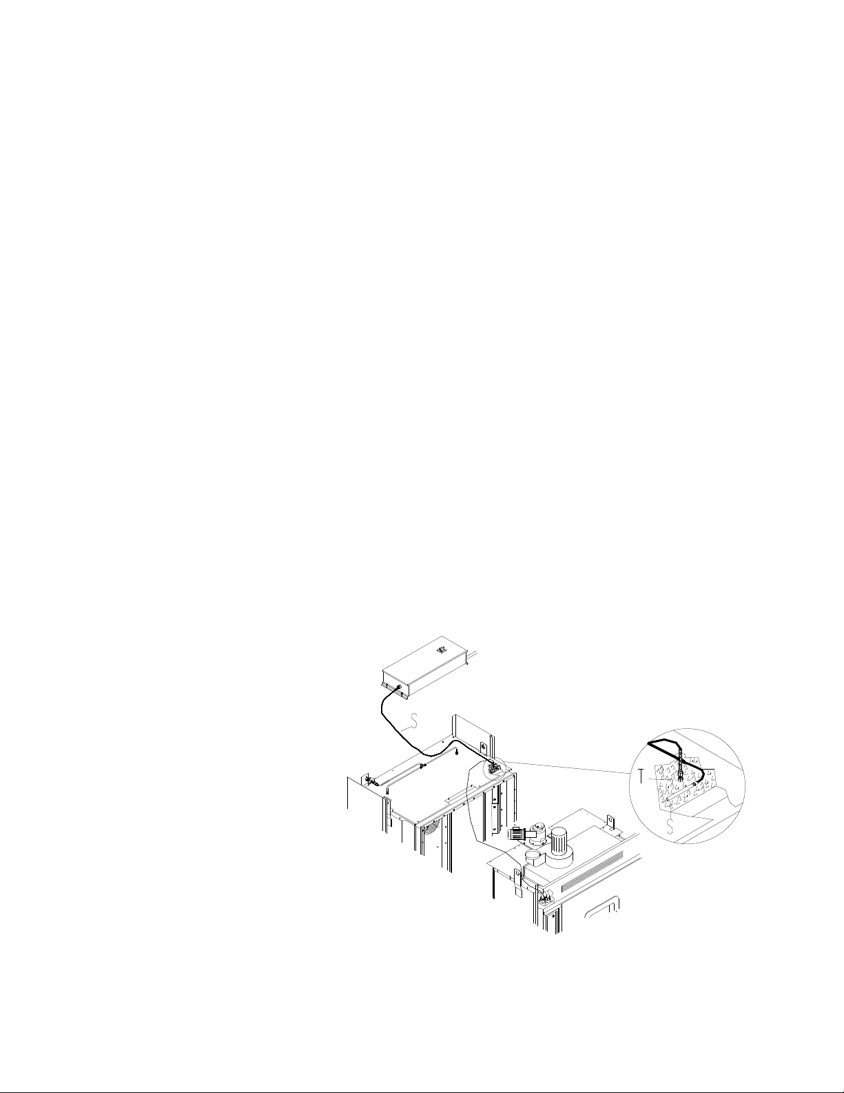
Screw the temperature probe “T” in its place and mount the high temperature probe “S”
under the insulating making sure it rests on top of the oven chamber.
Place the electric panel “9” outside on the oven, screw down and secure in position.
Mount electrical connection protection covers “10 – 11”.
Mount and screw the hood “12” at the front of the oven.
Place the door ramp in location slots “13” at base of front of oven.
T= Temperature Probe
S= High Temperature Probe
ROTORBAKE Series Ovens - electric version - Page 19
E
LECTRICAL
C
ONNECTION
!
Caution!
Only qualified personnel may carry out the electrical connection. Strict observance
of CEI specifications and regulations is required.
Check the oven setup, comparing the type of mains current and voltage available with the
levels shown on the serial plate. The electrical diagram is included in this manual.
The equipment may be connected to the mains only if a disconnect switch is included, with
at least 3 mm of open space between the contacts for each pole. The switch must be
located in an easily accessible position and close to the oven.
The connection cables must be at least type H07 RN-F. The minimum size and number of
wires may be found in the “Electrical specifications” table. Fixed connections require the
use of regulation cable channels.
Remove the terminal board cover, insert the cable in the holder and connect each wire to
the corresponding terminal. The plate near the terminal board indicates the correct
positions of phases and neutral.
Once the cable is connected to the terminal board, tighten the cable holder on the back of
the equipment and close the cover.
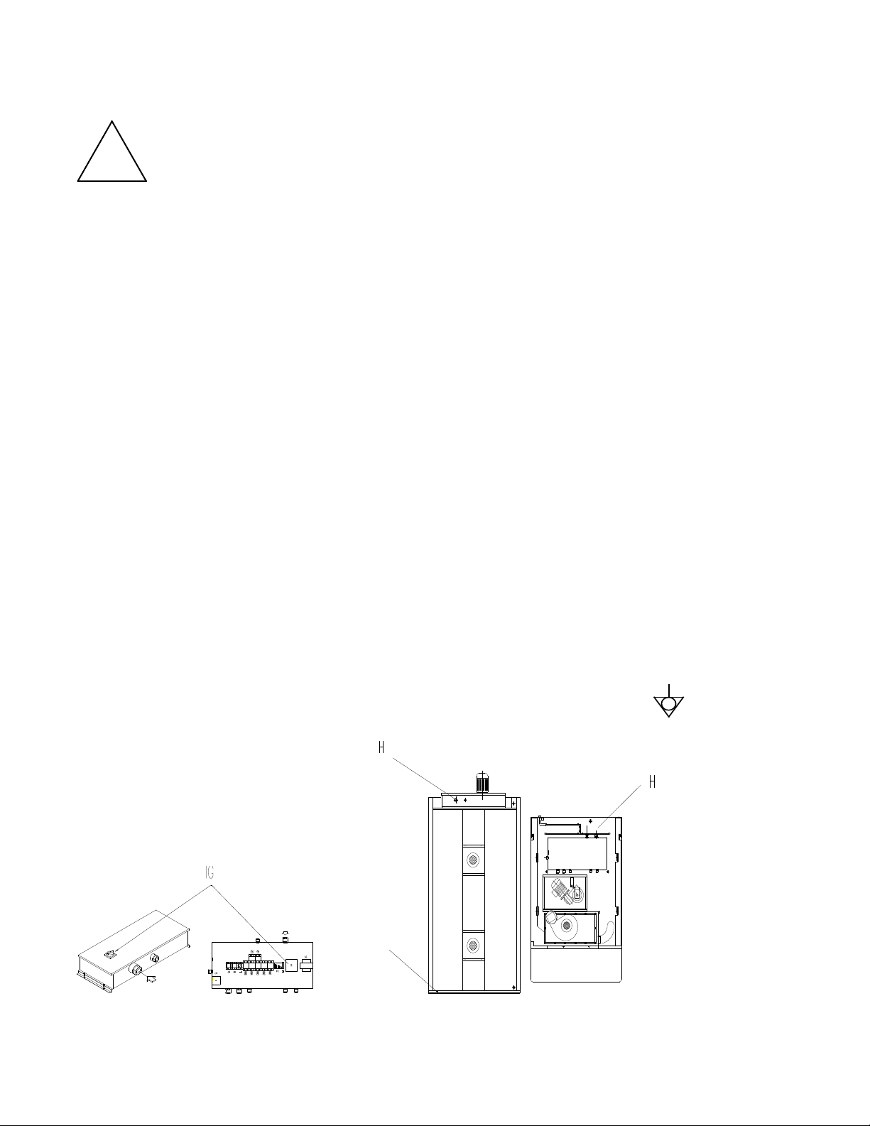
Electrical safety may be guaranteed only when the equipment is efficiently grounded as set
forth in current regulations.
The oven must also be included in an efficient equipotent system.
This connection is made using the special terminal marked with the symbol , located at
the back of the equipment.
G – Equipotent terminal
H – Power cord inlet
ROTORBAKE Series Ovens - electric version - Page 20
WATER AND DRAINAGE CONNECTION
Instant steam versions
A closure valve must be inserted between the equipment and the water mains. The
upstream water inlet must meet current regulations. The water inlet is located at the bottom
of the oven, and is duly marked.
Information about the permitted water pressure may be found in the paragraph “Water
connection”.
We recommend using softened water with a hardness level between 2 and 5° he.
We recommend a flexible hose to absorb small pressure peaks.
Run water through the pipes before making the connection.
Drainage takes place through a heat-resistant inflexible pipe (maximum length = 2 m).
Drainage water should lead to the drainage system by constant descent, and with a funnel
or siphon inserted. It is forbidden to reduce the diameter of the pipe.
!
Caution!
Incorrect drainage may lead to unpleasant odours in the cooking chamber!
C - Water inlet (¾’’)
D - Water outlet (½’')
ROTORBAKE Series Ovens - electric version - Page 21
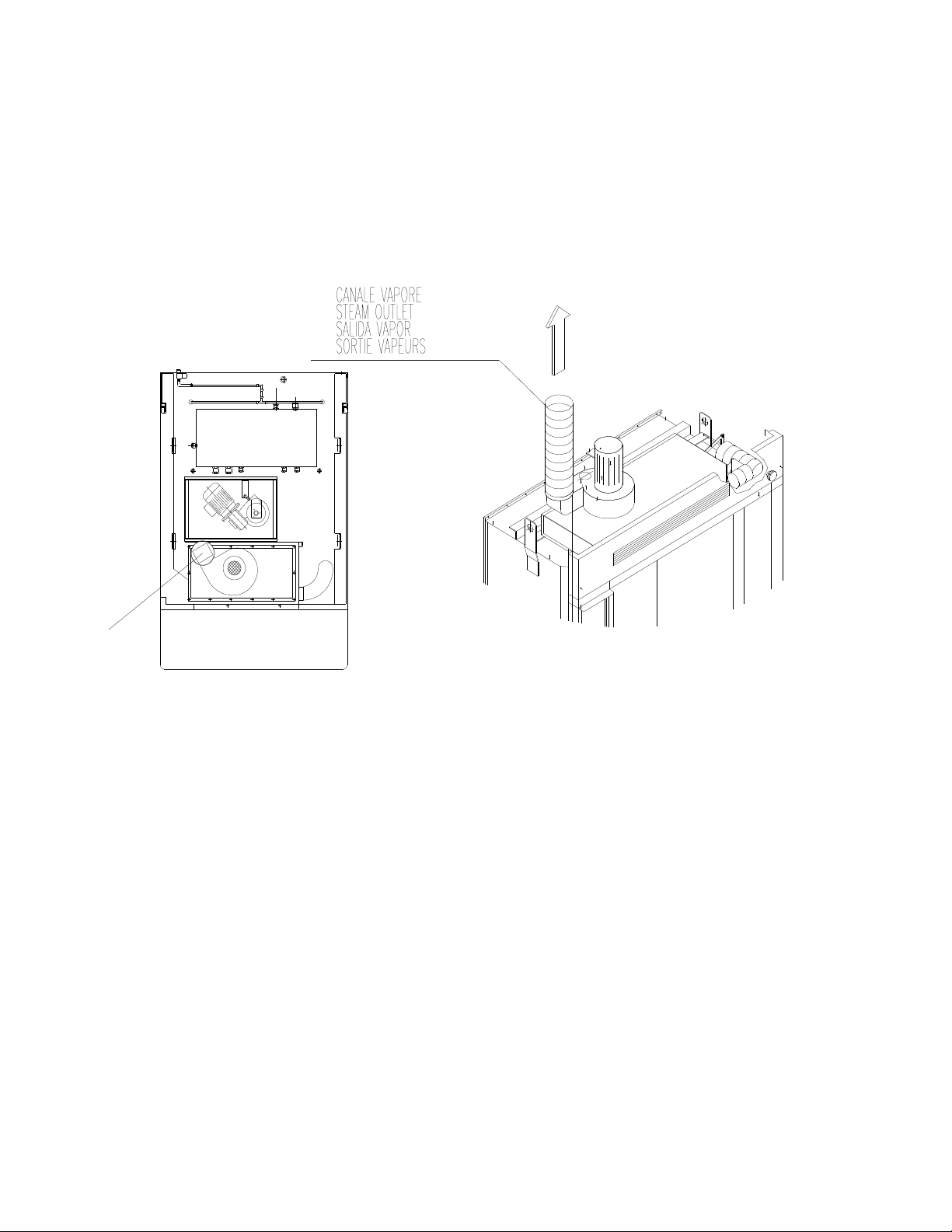
STEAM EXHAUST PIPE
The steam that is released from the baking chamber is vented into the atmosphere through
a special steam conduit. The steam conduit should be installed on the pressure opening of
the suction device.
At the base of each ascending tract of the chimney a collection chamber with a
condensation drainpipe must be constructed. There must be also an adequate opening for
inspection and cleaning.
J - Steam outlet
ROTORBAKE Series Ovens - electric version - Page 22
A
IR FLOW
A
DJUSTMENT
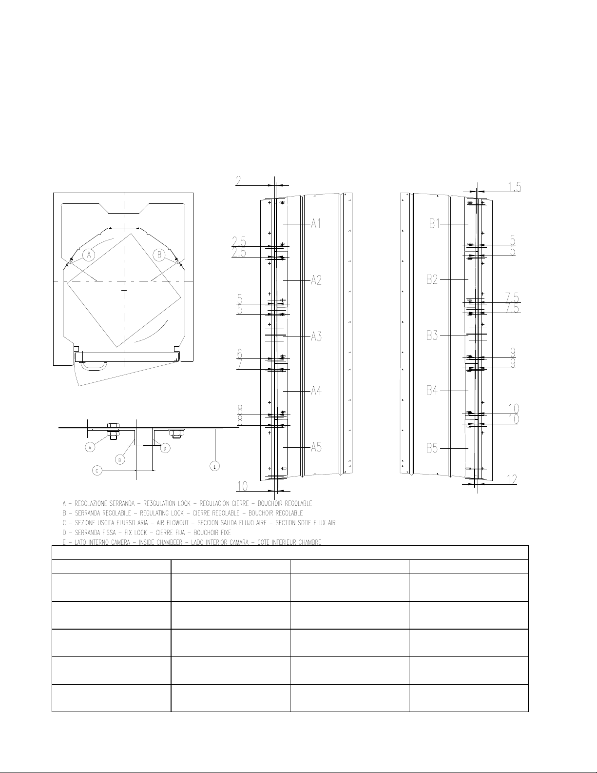
To ensure a more accurate distribution and more uniform baking, settle the air locks flow as
follow:
Turn the nuts M8 out that tighten the air locks “A – B” inside the oven.
Settle the openings of the air locks as shown in the table below.
Turn the nuts in as the opening shows in the table.
ADJUSTMENT AIR LOCKS
AIR LOCK“A” OPENING MM. AIR LOCK “B” OPENING MM.
A1
1 = 7
2 = 8
B1
1 = 7
2 = 8
A2
3 = 8
4 = 9
B2
3 = 8
4 = 9
A3
5 =9
6= 10
B3
5 = 9
6 = 10
A4
7 = 10
8 = 11
B3
7 = 10
8 = 11
A5
9 = 11
10 = 13
B3
9 = 11
10 = 13

ROTORBAKE Series Ovens - electric version - Page 23
S
TART
-
UP
PRELIMINARY STEPS
!
Caution!
Make sure that:
- All connections have been properly made;
- All protective covering has been completely removed;
- The baking pan guides are correctly mounted;
- The main power switch is on;
- For steam models: the water cut-off valve is open

ROTORBAKE Series Ovens - electric version - Page 24
USER INSTRUCTIONS
The oven may be delivered to the user only after all tasks and checks described in this
manual have been completed.
Explain to the user how the equipment works, especially in terms of safety, using the
instructions provided.
Point out to the user that any changes to the installation site that may affect the supply of
combustion air require that a specialized technician recheck its functions.
Recommend that the customer stipulate a maintenance contract with the customer service,
as this type of equipment requires at least one inspection per year.
ROTORBAKE Series Ovens - electric version - Page 25
ROTARY RACK
Insertion
- Make sure manual damper is closed.
- Set the timer on the steam control.
- Open the door completely.
- Ascertain that the steam suction fan goes on.
- Push rack into oven make sure rack is locked into position.
- Close and lock the door handle.
Removal
- A sound signal goes off at the end of the baking time.
- Start the removal procedure performing the following operations in the order listed:
- Open the manual steam vent.
- Unlock and open the door partially to allow any residual steam to be eliminated by the
suction unit.
- Holding the START button “T” down, rotate the cart to the extraction position.
- Open the door completely and, wearing heat resistant gloves, extract the rack.
- Close and lock the door.

ROTORBAKE Series Ovens - electric version - Page 26
O
PERATING
I
NSTRUCTIONS
USER SAFETY INSTRUCTIONS
!
Warning!
The equipment is ready to be started only when all connections are completed.
The equipment may operate safely only when the instructions below are carefully
followed.
The user may operate this equipment only after being duly instructed as to its use
and operation.
Remove covers and panel doors only using tools must not be removed for any
reason.
The equipment must not be used unsupervised!
The door becomes hot while the oven is working; use caution!
Proceed with caution when opening the door during operation and when the oven is
hot; hot steam may escape!
Protect the equipment from freezing.
Any work regarding installation, conversion to another type of gas, or repairs must be
carried out by qualified personnel and in compliance with current regulations.
Have specialized personnel from the manufacturer inspect the equipment at least
once a year. For this purpose, we recommend stipulating a maintenance contract.
The equipment must be cleaned daily. The equipment is not protected against
sprayed water; therefore, do not use water under pressure or direct sprays.
Note: The noise level for the work site is below 70 dB (A). This information is
essential for certain national safety regulations.
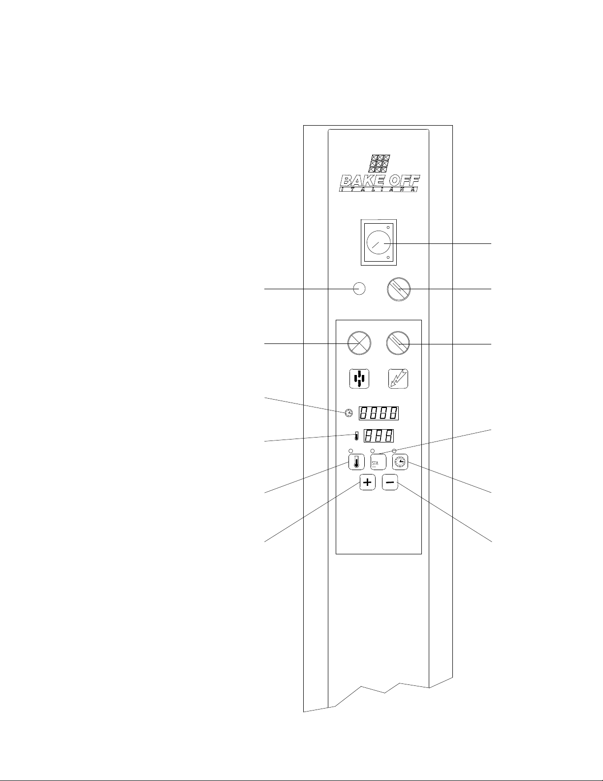
ROTORBAKE Series Ovens - electric version - Page 27
C
ONTROL
P
ANEL
E
XTRA
O
VEN
-
DIGITAL
M
ODEL
D - Fuse
E - Temperature setting
button
F - Water button for instant steam
G - Main switch
H - Digital timer
L - Hood vent switch
M - “Start” button
N - Baking time setting button
O - Digital thermostat
P - Decrease button
Q - Increase button
R - Steam timer
R
L
N
P
M
D
F
H
O
E
Q
G

ROTORBAKE Series Ovens - electric version - Page 28
Extra Model with Digital Controls
Setting the Temperature:
After turning on the oven using the main switch G, press the button E to set the
temperature regulator set point. The corresponding indicator lamp on top of the button
lights when activated.
The temperature display O will begin to flash, indicating the pre-set set point. Adjust by
pressing the + (Q) and - (P) buttons; press the E key once again to save.
Setting the Baking Time:
Press the N key to set the baking time set point, expressed in minutes and seconds.
The baking time display H will begin to flash in the minutes section, indicating the pre-set
set point. Adjust by pressing the + (Q) and - (P) buttons; press the N key once again to
save.
The baking time display H will begin to flash in the seconds section, indicating the pre-set
set point. Adjust by pressing the + (Q) and - (P) buttons; press the N key once again to
save.
Preheating:
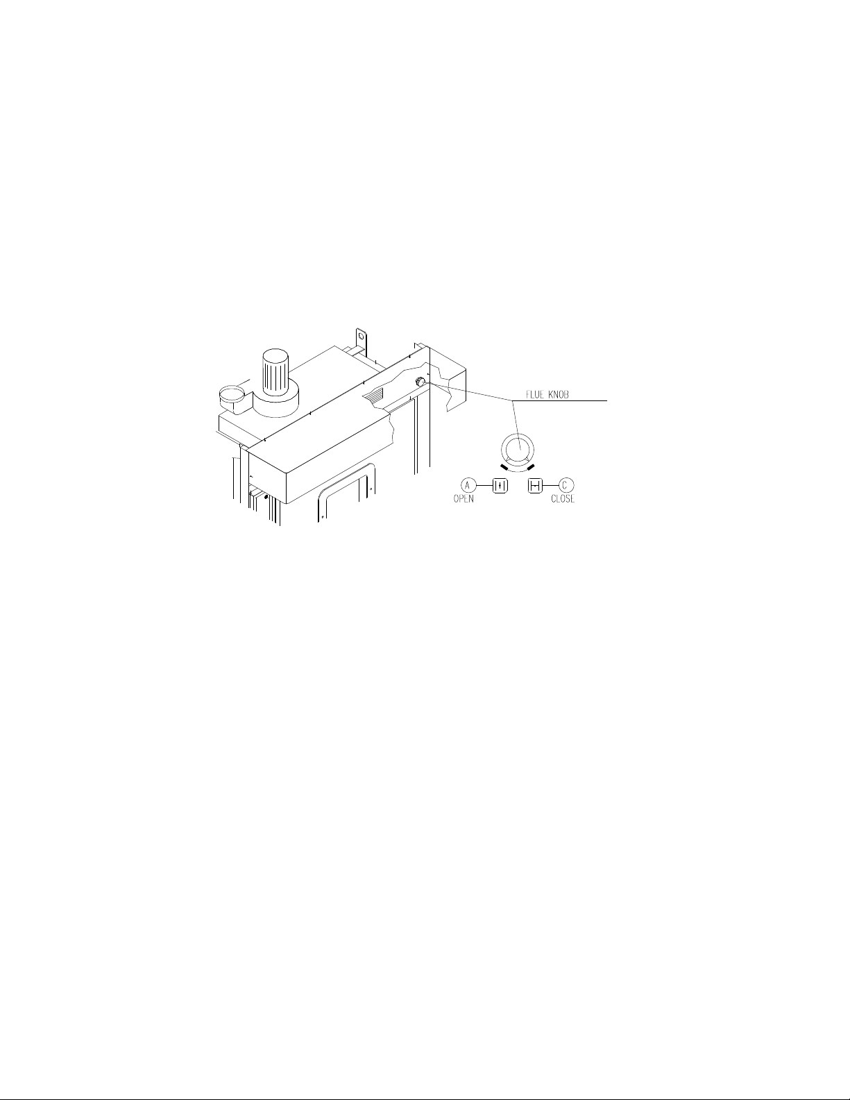
Set the flue valve knob B to the closed position C. Set the desired temperature as
described above. Hold the START key M down for at least 3 seconds, and the oven will
begin preheating.
BREAD BAKING:
(Baguettes, Buns, Bread products from 60 to 300 g)
Preheat the oven until it reaches the set preheating temperature (250°/260°).
Check the display O to make sure the oven has reached temperature, and then insert the
products in the oven.
When the door is opened, the oven immediately locks all functions to allow the operator to
insert the product in the baking chamber.
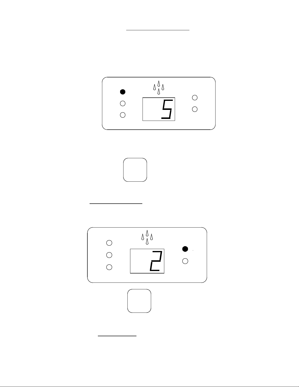
Once the product has been placed in the oven, make sure the door is properly closed, then
set the steam timer R according to the needs of the product to be baked, and press the
steam button F.
At this point the oven will automatically cease functioning for approximately 40 seconds
after the button is released, to allow proper steam distribution. It will then start again
automatically.
Set the temperature and the baking time (185°/200° - 18’/22’ depending on the type and
size of the bread) as indicated above, then start the baking timer by briefly pressing the
START button M. The LED indicator will flash and the timer will begin counting down.
When the timer shows 5 minutes of baking time remaining, turn the flue valve B to the open
position A to evacuate the baking steam from the chamber.

ROTORBAKE Series Ovens - electric version - Page 29
When baking is complete, the timer will beep a few times until you shut it off by briefly
pressing the START button M.
!
Warning!
The oven does not AUTOMATICALLY cease all functions at the end of the baking
time!
NOTE:
Opening the oven door stops all functions.
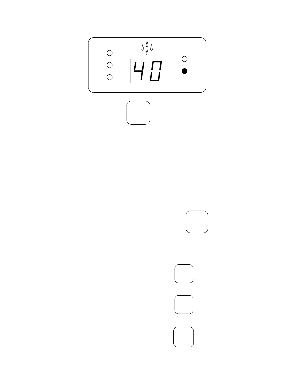
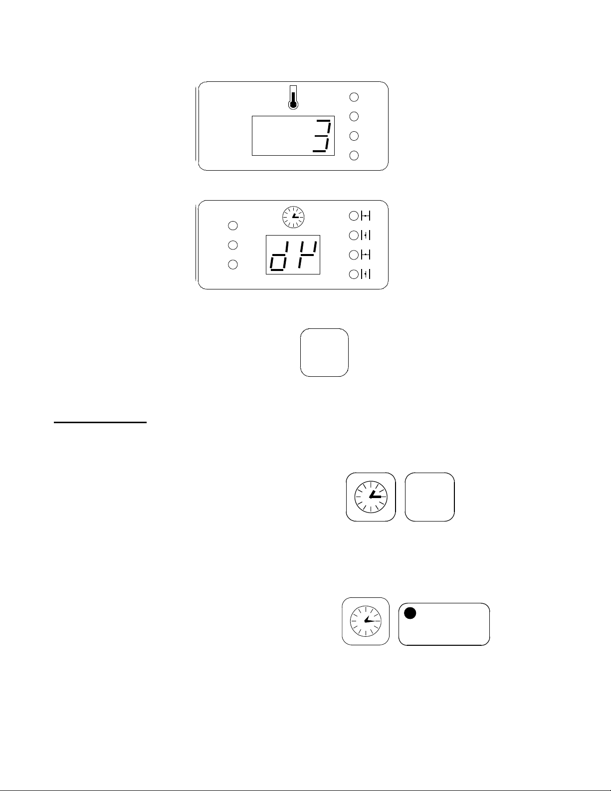
!
Warning!
In order to stop all oven functions completely, hold down the START button M for at
least 3 seconds. The following will appear:
Display (H), Timer -------------------------------------------------------------------------
Display (O), Temperature ----------------------------------------------------------------
PASTRY BAKING:
Preheat the oven until it reaches the set preheating temperature (approximately 20° above
the product baking temperature).
Check the display O to make sure the oven has reached temperature, and then insert the
products in the oven.
When the door is opened, the oven immediately locks all functions to allow the operator to
insert the product in the baking chamber.
Once the product has been placed in the oven, make sure the door is properly closed, then
set the temperature and baking time (170°/185° - 15’/18’ depending on the type and size of
the products) as indicated above, then start the baking timer by briefly pressing the START
button M. The LED indicator will flash and the timer will begin counting down.
When baking is complete, the timer will beep a few times until you shut it off by briefly
pressing the START button M.
!
Warning!
The oven does not AUTOMATICALLY cease all functions at the end of the baking
time!
NOTE:
Opening the oven door stops all functions.
00-00
-- -- --

ROTORBAKE Series Ovens - electric version - Page 30
!
Warning!
In order to stop all oven functions completely, hold down the START button M for at
least 3 seconds. The following will appear:
Display (H), Timer -------------------------------------------------------------------------
Display (O), Temperature ----------------------------------------------------------------
Stopping the Oven Prematurely:
Should you wish to stop a baking process already in progress, hold down the Start button
(M) for at least 3 seconds.
AUTOMATIC TIMED PREHEATING:
One of the features of the digital-control Extra model is the possibility to preheat the oven
at a set time, for example, to allow the operator to find the oven ready to use and at the
correct working temperature when he arrives at work.
The first step is to adjust the clock: hold down the N button for at least 6 seconds. The
display H will begin to flash in the hours portion, indicating the pre-set set point. Use the +
(Q) and - (P) keys to change the time. Save by pressing the N key once again. The minutes
will now be flashing, indicating the pre-set set point. Use the + (Q) and - (P) keys to change
the time. Save by pressing the N key once again.
Stop all oven functions entirely by holding down the START button M for at least 3
seconds.
To set the starting time for automatic preheating, hold down the + (Q) and - (P) buttons
simultaneously for at least 3 seconds. The display H will begin to flash in the hours
portion, indicating the pre-set set point. Use the + (Q) and - (P) keys to change the time.
Save by pressing the N key once again. The minutes will now be flashing, indicating the
pre-set set point. Use the + (Q) and - (P) keys to change the time. Save by pressing the N
key once again. Set the preheating temperature as described above.
Now, briefly press the start key M. The corresponding indicator LED R will begin flashing,
indicating that the automatic preheating function is working properly
When the set time arrives, the oven will start and bring itself to the preheating temperature.
Then you may insert the product, set the desired temperature and baking times, and briefly
press the start key M to start the baking time countdown.
00-00
-- -- --
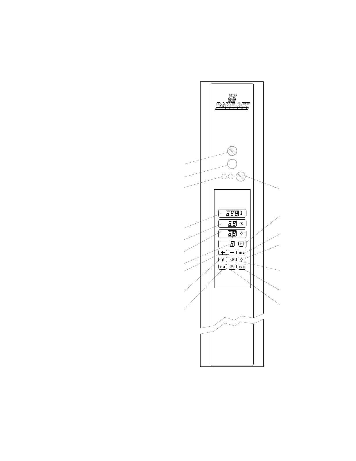
ROTORBAKE Series Ovens - electric version - Page 31
C
ONTROL
P
ANEL
E
XTRA
O
VEN
- 10 P
ROGRAMS
E
LECTRONIC
M
ODEL
A
- R
ACK
rotation button
B - Flue knob
D - 6,3 A fuse
F - Temperature display
G - Main switch
H - Timer
I - Steam injection display
L - Program display
N - Program button
O - Increase button
P - Memory button
Q - Steam regulator button
R - Temperature regulator button
S - Start button
T - Time regulator button
U - Stop button
Z - On - Off button
B
A
D
F
H
I
O
R
U
Z
S
T
Q
P
N
G
L

ROTORBAKE Series Ovens - electric version - Page 32
OPERATION AND FUNCTIONS OF THE 10 PROGRAMS EXTRA OVEN
THE OVEN:
The BAKE OFF 10 PROGRAMS EXTRA MODEL oven is designed to simplify the baking
of different items such as breads of all kinds, confectionery, pizza, etc.
Using computerized technology, it is able to memorize 10 programs for baking the same
number of different products, optimising all the parameters, which may vary while baking is
in progress.
Once all the programs to be used have been set, the operator has only to recall the number
of the program required and start baking.
Using an internal clock, the oven is also able to start baking at a preset time, so that the
operator can find the oven ready at the required temperature when he arrives at work.
INFORMATION ABOUT PROGRAMS
Before setting the definitive baking programs, users are advised to read the whole section
relating to use of the oven.
In each program, all the parameters essential for baking must be set: baking time, baking
temperature and steam injection time.
HOW TO SET PROGRAMS
Make sure that all oven connection procedures have been carried out correctly, then term
the main switch G, and turn on the oven’s computerized control by pressing the on - off
key:
First select the baking program to be set by pressing the program key N ; the relative
number will start to flash on the program display L, modify this number using the (+) key O,
and the (-) key M, then confirm the setting by pressing the Enter key P.
Then memorize the baking temperature of this program by pressing the Temperature key
R; the relative display F, will start to flash, modify the baking temperature using the (+) key
O, and the (-) key M, then confirm the setting by pressing the Enter key P.
The next step is to memorize the baking time, indicated in minutes, by pressing the Time
key T, the relative display H, will start to flash, modify the baking time using the (+) key O,
and the (-) key M, then confirm the setting by pressing the Enter key P.
To conclude, memorize the steam injection time, indicated in sencods, by pressing the
Steam key Q, followed by the (+) key O, and the (-) key M, then confirm the setting by
pressing the Enter key P.

ROTORBAKE Series Ovens - electric version - Page 33
BAKING
Turn the main switch G, and turn on the oven’s computerized control by pressing the on -
off key:
Select the baking program for the product to be baked by pressing the program key N; the
relative number will start to flash on the Program display L, modify this number using the
(+) key O, and the (-) key M, then confirm the setting by pressing the Enter key P.
Press the Start key S, to begin an automatic phase, which will bring the oven to the
preheating temperature, 50 degrees higher than the temperature set in the baking program.
On completion of this phase, a buzzer will inform the operator that the oven is ready to start
baking.
When the door is opened the oven will switch off, allowing the operator to place the product
inside.
Once the product is in the oven, the operator has only to check that the door is properly
closed; the oven will continue automatically until baking is complete.
To vary the programmed temperature temporarily during the baking, simply press the
Temperature key R, modify using the (+) key O, and the (-) key M, then confirm by
pressing the Enter key P.
Note that the variation made in this way will only be active for the baking cycle in progress
and will not be memorized in the baking program selected.
!
Warning!
At the end of the baking time the oven does not stop its functions
AUTOMATICALLY!
!
At the end of the baking time, the oven will sound a beeper until you give the baking end
command by pressing the Stop key U, or by simply opening the oven door.
Baking in accordance with the program you selected previously is now complete, but a new
temporary “baking time” can be set to further prolong baking.
If this is required, press the Time key T, and the relative display H, obviously showing zero,
start to flash; modify the baking time using the (+) key O, and the (-) key M, then confirm
by pressing the Enter key P.
This function is only available within 60 second after the end of the programmed baking
and is indicated by flashing of the led on the Stop key U.

ROTORBAKE Series Ovens - electric version - Page 34
AUTOMATIC TIMED PREHEATING
One of the features of the 10 Programs Extra Electronic model ovens is that the oven can
be preheated at a preset time, so that the operator can find the oven already at the
required temperature when he arrives at work.
First the clock has to be set.
Press key T for at least 5 seconds, the display H will start to flash on the hour figure,
indicating the existing set point, use the (+) key O, and the (-) key M to modify the setting
and then memorize the hours by pressing the Enter key P; the minutes will now start to
flash, indicating the existing set point; use the (+) key O, and the (-) key M to modify the
setting and then memorize the minutes by pressing the Enter key P again.
To conclude, the display will flash indicating the day of the week with a number (e.g.
Monday = 1, Tuesday = 2 .....) modify using the (+) key O, and the (-) key M, then confirm
by pressing the Enter key P.
Stop all oven functions by pressing the Stop key U.
To set the starting time for automatic preheating, press the Enter key P, and the Clock key
T, in that order, the display H will start to flash on the hour figure, indicating the existing set
point, using the (+) key O, and the (-) key M, to modify the setting end then memorize the
hours by pressing the Enter key P.
The minutes will now start to flash, undemanding the existing set point, using the (+) key O,
and the (-) key M, to modify the setting end then memorize the hours by pressing the Enter
key P again.
The display H will mow show the number of days’ delay before the timed start-up (e.g.
today = 1, tomorrow = 2 ......); to modify use the (+) key O, and the (-) key M, then confirm
the setting by pressing the Enter key P.
To allow use of this function, the oven must continue to receive power and the main switch
G must be left turned to ON.
Then select the baking program to be carried out at start-up, as explained previously, and
press the clock key T and the Start key S, in that order.
If this function has been set correctly, the led on the Start key S will flash and the Time
display H and the Steam display I will switch off, while the temperature and the program set
will continue to be displayed on the displays F and L respectively.
When the preset time is reached, the oven will come into operation and heat to the
preheating temperature; to start the baking program as such, simply open the door and
place the product inside.
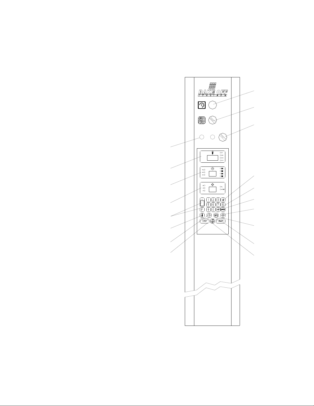
ROTORBAKE Series Ovens - electric version - Page 35
CONTROL PANEL
E
XTRA
O
VEN
- 100 P
ROGRAMS
E
LECTRONIC
M
ODEL
A
- Temperature display
B - Timer display
C - Steam display
D - Fuse
E - Miscellaneous program display
F - Temperature regulator button
G - Main switch
H - Regulator baking time button
L - Switch hood
M - Set button
N - Stop button
P - Enter button
Q - Water button
R - Programming keyboard
S - Flue fume regulator
T - Rack rotation button
U - Start button
V - On-Off button
T
L
G
R
M
P
Q
S
U
V
D
A
B
C
E
F
H
N

ROTORBAKE Series Ovens - electric version - Page 36
"# $%&& ! '
The Oven:
The BAKE OFF 100 PROGRAMS MODEL is an oven designed to facilitate and maximize
baking various products, such as all kinds of breads, pastries, pizza, etc.
Its computerized technology allows it to memorize up to 100 programs for baking the same
number of different products, maximizing all of the parameters that may change for baking
each.
Once all useful programs have been set, the operator need only call up the corresponding
program number and bake.
The oven uses an internal clock, and may therefore be started at a pre-set time so that, for
example, the operator can find the oven at temperature upon arriving at work.
Information about the Programs:
Before setting the final baking programs, it is best to read the entire paragraph about using
the oven.
Each program is divided as follows:
SP
OVEN PREHEATING
SP1
INITIAL BAKING PHASE
SP2
SECOND BAKING PHASE
SP3
FINAL BAKING PHASE
The time, baking temperature and any steam injections at the start of each phase may be
programmed for each baking phase.
Each program also controls 2 timed open-close phases of the flue valve to evacuate
baking steam.
How to Set Up the Programs:
Make sure that the oven has been properly connected, then turn the main switch G and
turn on the computerized oven control by pressing the key:
ROTORBAKE Series Ovens - electric version - Page 37
Setting up a program:
Choose the program to set:
Press the following keys consecutively:
Press the number of the program to be saved:
Then the key:
This will take you to the set point of the selected program, whose number will be flashing
on the program display.
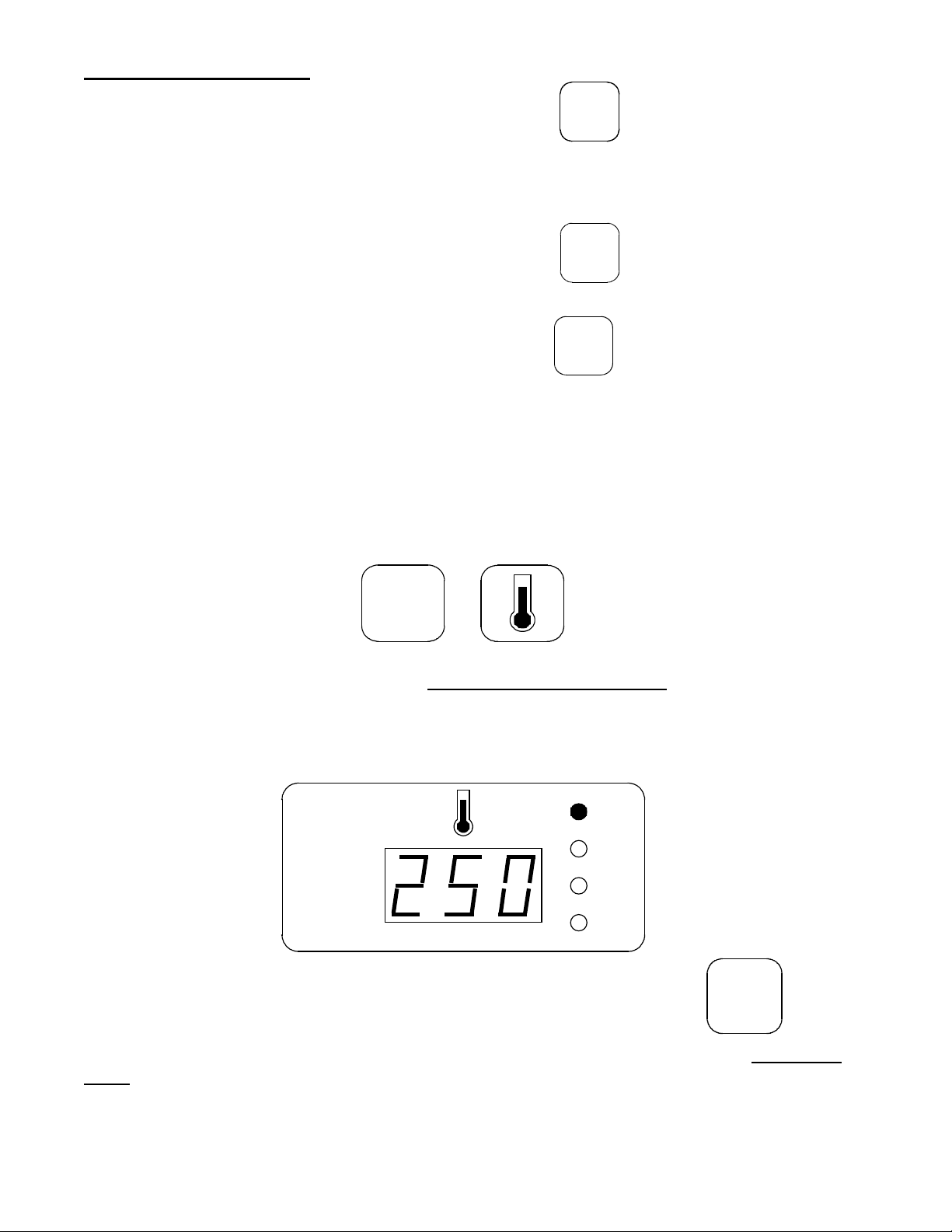
EXAMPLE:
The first parameters to be saved are those for the baking temperature.
Therefore, press the keys:
to enter the temperature set point.
The first temperature to enter is for the SP phase (oven preheating), which is usually 50
degrees above the ideal baking temperature.
Then enter the temperature on the numerical keypad; e.g., 250°. The flashing SP LED will
show this. Make sure that the temperature display reads:
then save the preheating temperature using the key:
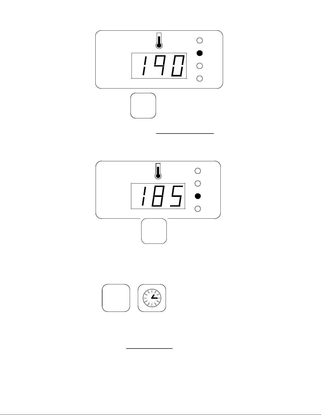
Once this step is complete, you may move on to set the SP1 temperature of the first baking
stage, e.g. 190°.
Make sure that the temperature display reads:
ROTORBAKE Series Ovens - electric version - Page 38
then save using the key:
You may now set the SP2 temperature of the second baking stage
, e.g. 185°.
Make sure that the temperature display reads:
then save using the key:
Perform the same steps for the third stage.
Now save the parameters for the baking times;
press the keys:
to enter the baking time set point.
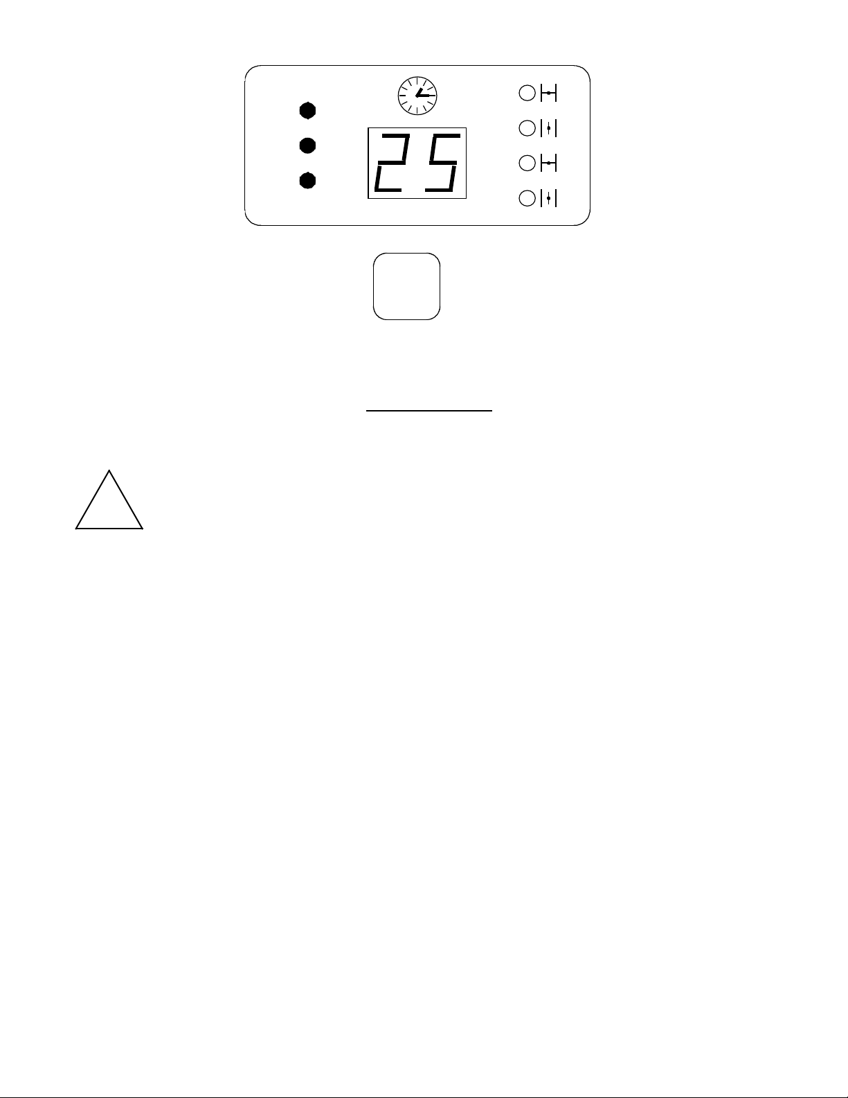
The first parameter to be set is the total baking time, indicated by flashing LEDs tc1, tc2,
tc3, e.g. 25 minutes.
Make sure the time display reads:
ROTORBAKE Series Ovens - electric version - Page 39
then saving using the key:
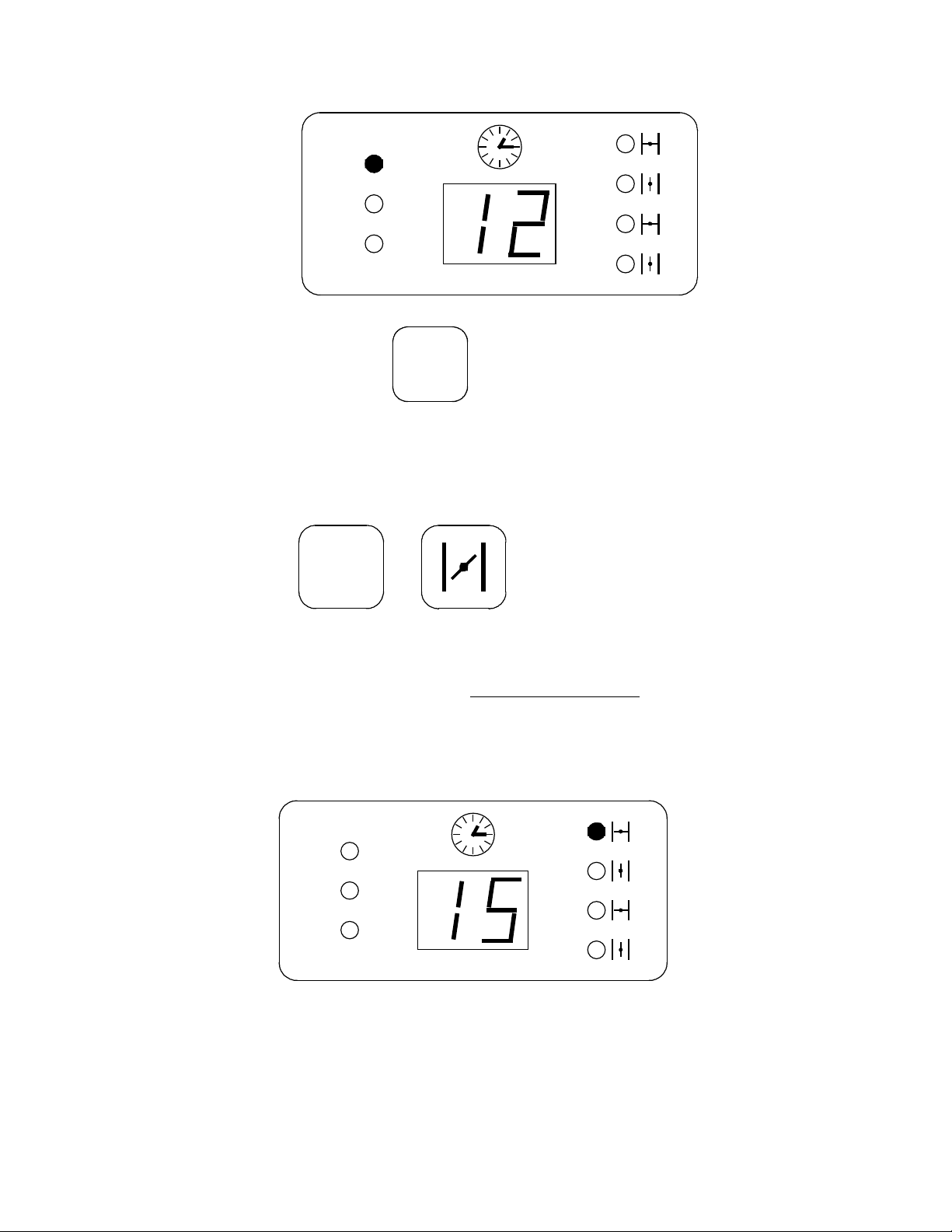
Now move on to set the duration of the first baking stage
, e.g. 12 minutes
!
Warning!
The sum of the three baking stages must obviously match the previously set total
baking time.
ROTORBAKE Series Ovens - electric version - Page 40
Make sure the time display reads:
then saving using the key:
Perform the same steps for the remaining baking times.
Now move on to save the parameters concerning the steam flue opening;
press the keys:
to enter the flue control set point.
The first parameter to be set is the one for the first flue closing time
, which begins at the
start of baking. E.g.: if you wish for the flue to remain closed for 15 minutes when baking
begins, set the set-point as follows:
Make sure the time display reads:
(If you want the flue to remain open when baking begins, set this parameter to = 0)
ROTORBAKE Series Ovens - electric version - Page 41
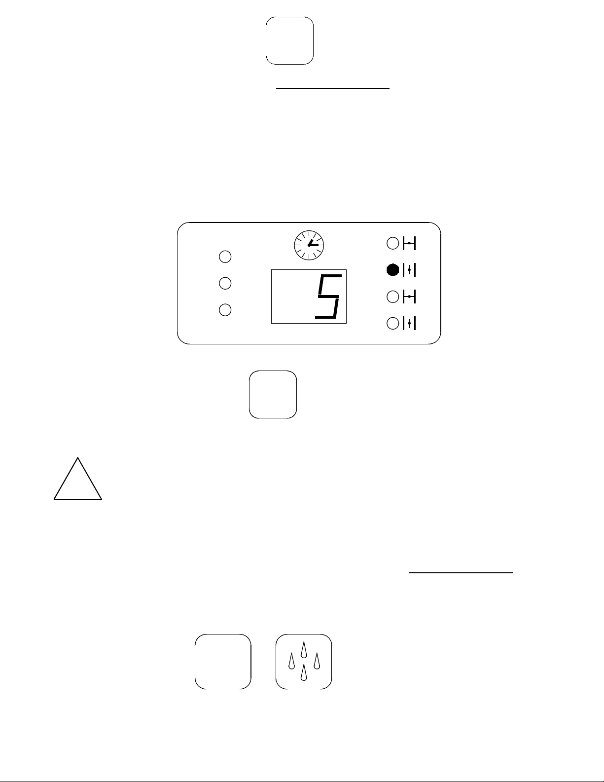
then saving using the key:
Now move on to set the parameter for the first flue opening time
, which begins at the end of
the previous stage.
E.g.: I want the flue to remain open for 5 minutes:
Make sure the time display reads:
then saving using the key:
Perform the same steps for the remaining open-close flue cycle
!
Warning!
The sum of the two-cycle duration must obviously be the same as the previously set
total baking time.
If you wish to control only one flue open-close cycle, the sum of the first two parameters will
equal the previously set total baking time.
Then move on to save the parameters concerning steam injections;
press the keys:
to enter the steam injection control set point.
ROTORBAKE Series Ovens - electric version - Page 42
The first parameter to be set is for the first steam injection time
, which begins at the start of
the first baking stage, and is measured in seconds.
E.g.: 5 seconds.
Make sure the steam display reads:
then save by pressing:
Now move on to set the number of injections lasting 5 seconds.
E.g.: 2.
Make sure that the steam display reads:
then save by pressing:
YES, You may now set the fan pause time to allow steam to form correctly (BAKE OFF
recommends always leaving this parameter at 40 seconds).
ROTORBAKE Series Ovens - electric version - Page 43
Make sure that the steam display reads:
then save by pressing:
Perform the same steps for the remaining steam injections.
(If you wish to control a single steam injection, set the second and third injection time
parameters to 0 in the remaining steam injection cycles)
When the last parameter of the steam injection set point is saved, the entire program is
automatically saved as well.
PROGRAMMED BAKING
Make sure that the oven has been properly connected, then turn the main switch G and
turn on the computerized oven control by pressing the key:
Recall and save the desired baking program
Press the following keys consecutively:
The program number to call up is:
then save by pressing:
ROTORBAKE Series Ovens - electric version - Page 44
to start the program, press:
When these steps are completed, the oven begins the program starting with preheating,
after which the oven will beep intermittently.
The oven is now ready to begin baking; insert product.
As soon as the door is closed again, the baking stages will automatically begin using the
parameters set in the program. This will be confirmed when by the lighted LED:
!
Warning:
One or more parameters may be changed for any baking stage in progress; the
change will be effective only for the current baking session and is not saved to the
program.
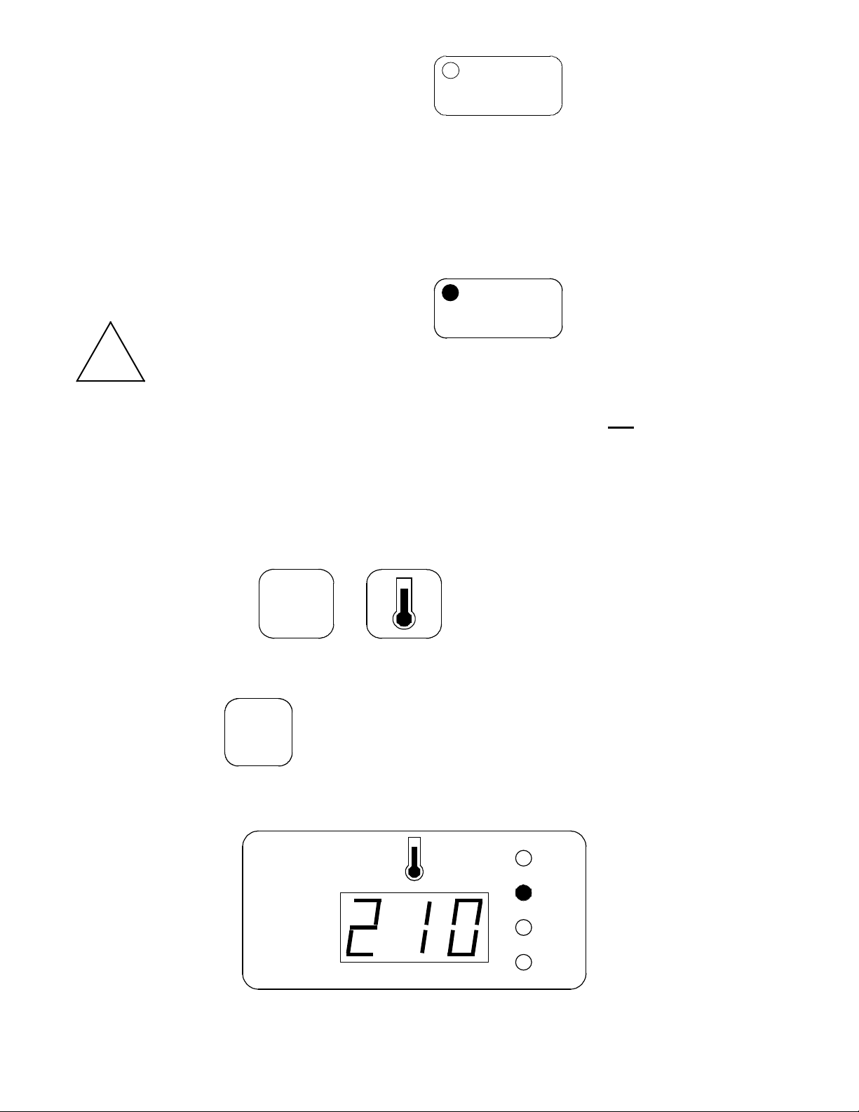
Example: While baking with program number 5, you wish to change the temperature during
the first baking stage from 190 to 210 degrees:
Press the keys:
Press the keys: to prevent changing the SP temperature for the
preheating stage
Enter 210 on the numerical keypad, and make sure that the temperature display reads:
then save by pressing:

ROTORBAKE Series Ovens - electric version - Page 45
When baking is finished, the oven will beep a few times and stop working to allow the
operator to remove the product from the baking chamber.
!
Warning:
If the product needs more baking time, within one minute will be possible, using the
same process done previously
set temporarily the time in minutes in order to extend the baking.
AUTOMATIC TIMED STARTING
One of the features of the BAKE OFF electronic model is automatic timed starting, which
allows for example the operator to find the oven already at temperature upon arriving at
work.
In order to use the oven taking advantage of this function, it must be powered and have the
main switch set to ON. The computerized control may be turned off using the key:
How to set the clock:
Example: Wednesday, 6:13 p.m. (18,13 on a 24-hour clock)
First, press the following keys consecutively:
Then enter 18 on the numerical keypad; make sure that the displays read:
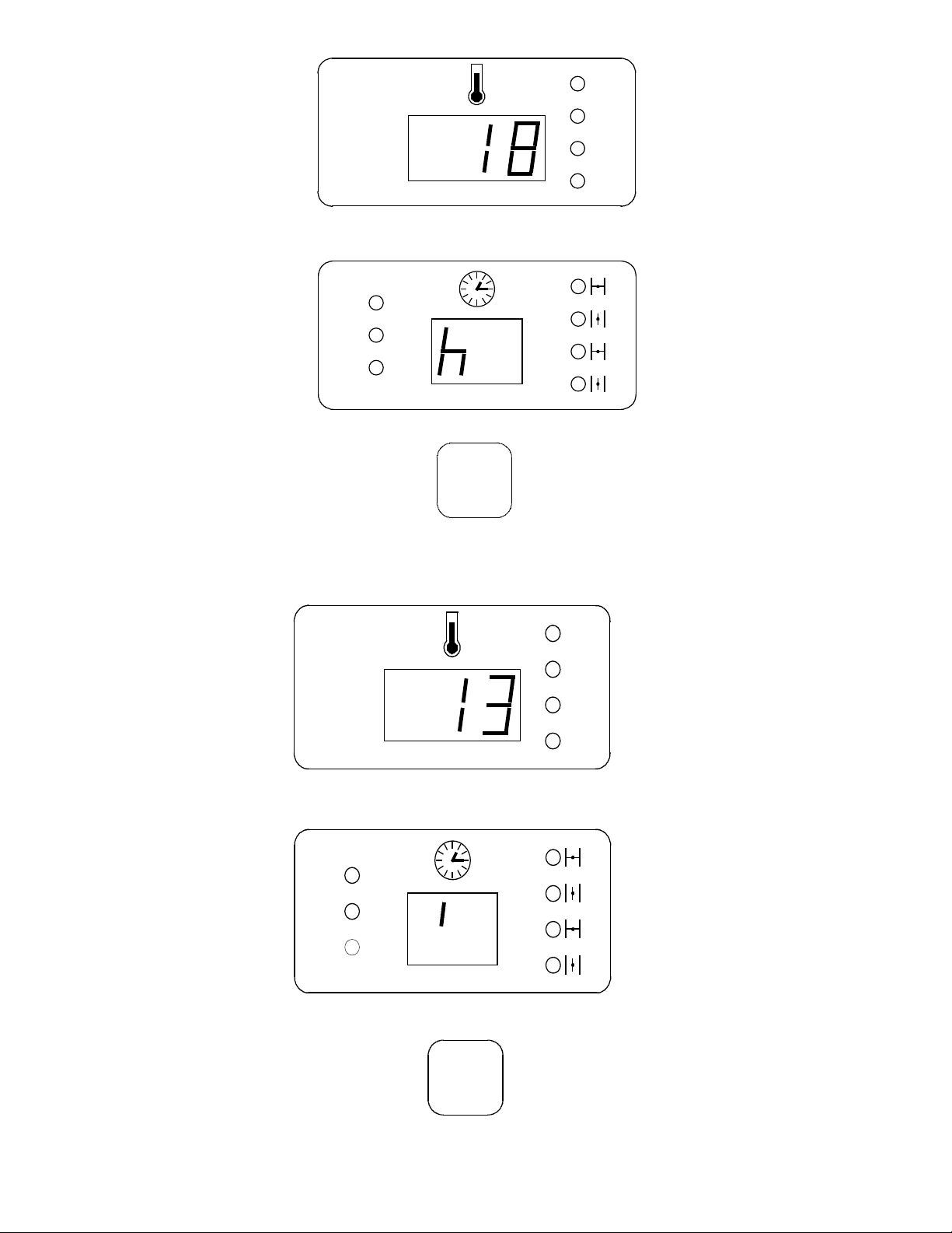
ROTORBAKE Series Ovens - electric version - Page 46
then save the hour by pressing
Enter 13 on the numerical keypad; make sure that the displays read:
then save the minutes by pressing:
ROTORBAKE Series Ovens - electric version - Page 47
(The day of the week is indicated by a number: Monday = 1, Tuesday = 2, etc.)
Enter the number 3 on the numerical keypad; make sure that the displays read:
then save the day by pressing:
Delayed start:
Call up and save the desired baking program as described previously. Then press the
following keys consecutively:
set and save the hour, minutes and day as described above.
Press the following keys consecutively:
The correct working of the function Start delayed is because of the lighting of the led on the
key start.
Now, the oven will begin the set program at the set time, even if the computerized control is
turned off.

ROTORBAKE Series Ovens - electric version - Page 48
S
HUTTING OFF THE
O
VEN
S
TANDARD
D
IGITAL
M
ODEL
The oven must be turned off
after baking. Turn the k
nob
G
to the OFF position and
the knob H to 0.
E
XTRA
10P
ROGRAMS
M
ODEL
Deactivate the oven after
baking by pressing the start
keys, turn the knob G
and
main switch to the OFF
position.
E
XTRA
100P
ROGRAMS
M
ODEL
After baking, turn off the
oven and turn the knob G
to
the OFF position.

ROTORBAKE Series Ovens - electric version - Page 49
C
LEANING AND
C
ARE
!
Warning!
The equipment must never be cleaned using a high-pressure cleaner or
direct water spray.
Cut off power to the oven when cleaning.
Clean the equipment only when cool.
Do not use cold water on the warm glass of the door.
The oven must be cleaned daily!
The outer steel surface of the oven may be cleaned using a damp cloth, with common
household cleansers if needed, then dried. We do not recommend using scratchy, abrasive
or corrosive products, which could damage the surfaces. Additional care may be taken by
using products specifically developed for cleaning steel. In this case, follow the label
instructions for the product.
We recommend using specific oven cleaning products for cleaning the baking chamber.
Here again, follow the manufacturer’s directions for using the product.
Hazardous cleaning products must not be used for any reason.
B
REAKDOWN
M
EASURES
Should a breakdown occur despite proper use of the oven, shut off the oven, close all
connections and call an authorized technician from the customer service centre.
E
XTENDED
DOWNTIME M
EASURES
Whenever the equipment is to remain unused for prolonged periods (seasonal closing,
vacation, etc.), we recommend cleaning it according to the instructions above and drying it
immediately. Disconnect all electrical devices, and shut all upstream cut-off valves.
ROTORBAKE Series Ovens - electric version - Page 50
Annual Maintenance
At least once a year the oven must be subjected to careful maintenance, to be performed
by the authorized customer service center.
This periodic maintenance must include the following points:
- Functional check of available devices
- Connector cable grounding check
- Water connection check (filling and drainage).
- Lubricate the gear motor
- Clean the door gaskets
- Replace lamps for inside light
Any parts must be replaced solely by personnel authorized by the manufacture or trained
and prepared for this purpose.
All spare parts must be requested directly from the manufacturer!
ROTORBAKE Series Ovens - electric version - Page 51
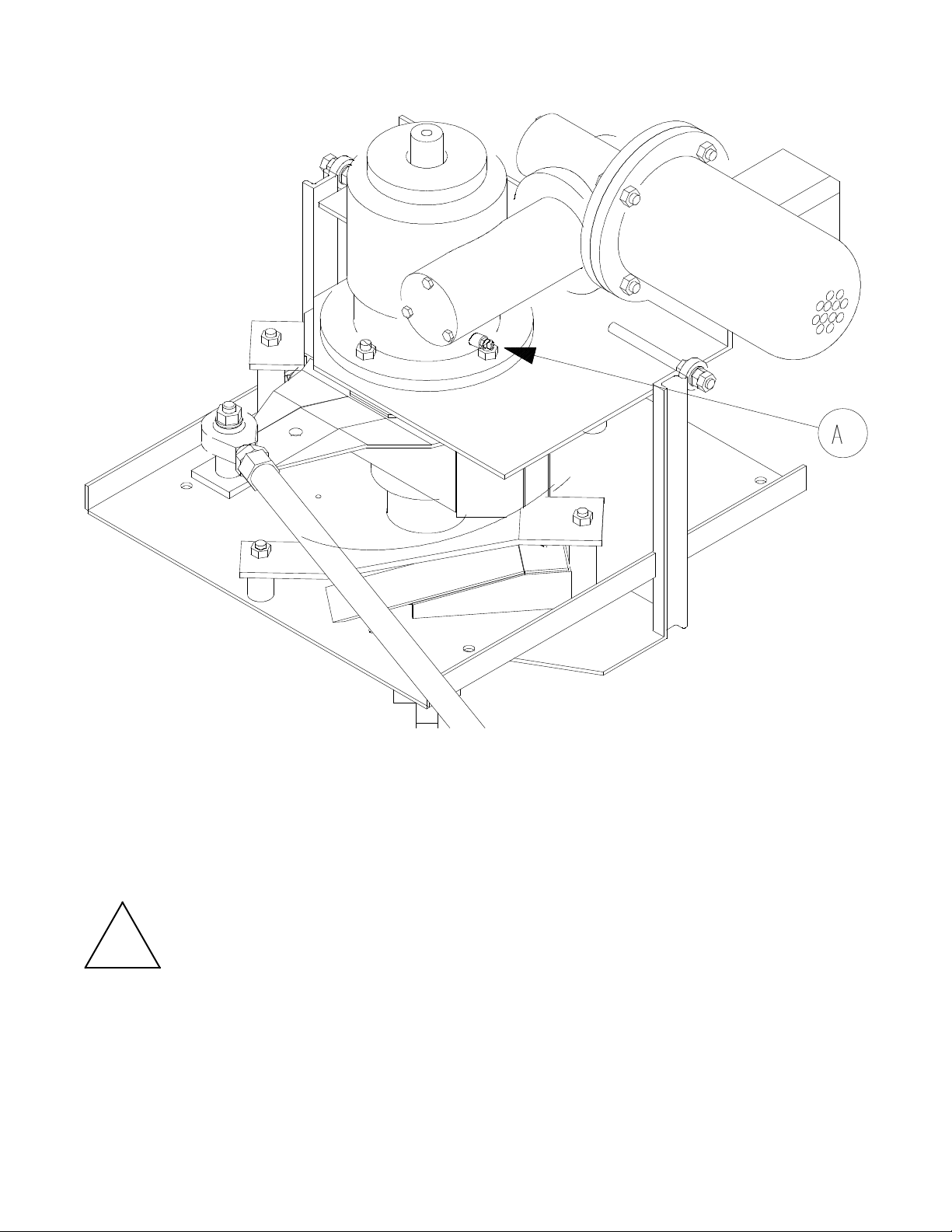
MAINTENANCE GEAR MOTOR (AUTOMATIC LIFT MODEL)
To avoid eventual damages at lifting and rotation rack group, we advise to supply the
lubrification of the bearing of the gear motor at least once a mounth.
The lubrification is made introducing grease for bearings ( high temperature resistant)
inside the ring shape part of the gear motor using the suitable grease box put at the bottom
of it ( “A”point ).
!
Warning
!
In case of malfunction of the rack rotation during the baking, you can do the lubrification.

ROTORBAKE Series Ovens - electric version - Page 52
M
ALFUNCTION CAUSES
QUALIFIED PERSONNEL
Qualified personnel must perform any operations on the electronic components of the
machine only, with excellent knowledge of the operation of the electrical parts and of the
precautions to be taken in handling them so as to avoid injury to him or others.
R
ACK
The cart does not stop or does not rise if the overload cut out on the control panel has been
tripped or the limit switch on the door handle is broken or out of place.
AIR RECYCLE FAN
The air recycle fan does not start if the overload cut-out on the control panel has been
tripped or the limit switch on the door handle is broken or out of place
S
TEAM PRODUCTION
The steam production is out of order if:
- The overload cutout on the control panel has been tripped.
- The suction unit is revolving counter clockwise
- The suction grid is clogged
- The drain pipe is clogged
I
NSUFFICIENT MOISTENING
- Not enough water in the humidifier, due to low water supply pressure or obstruction in
the humidifier hydraulic circuit.
- The temperature in the baking chamber is too low.
W
ATER LEAK
- Foreign bodies in the water intake solenoid
H
OT AIR FLOW LEAK WITH DOOR CLOSED
- Worn sealing gaskets
U
NEVEN BAKING
- The suction unit is revolving counter clockwise
- The air locks regulating air flow are not correctly oriented
D
ULL AND ROUGH BREAD
- Not enough moisture

ROTORBAKE Series Ovens - electric version - Page 53
R
EQUESTING SERVICE
For the malfunction causes contact the requesting service.
O
VEN SERVICE
- If the cause of the malfunction is attributed to the oven, contact the authorized retailer
you purchased it from. Our authorized retailers are able to supply information about
most of the products they handle and should be able to provide consultation service on
any problem you may have with the oven.
Any service calls should be arranged on the basis of the seriousness of the problem. In
cases of ordinary maintenance the service call will be scheduled on a mid-term basis.
ROTORBAKE Series Ovens - electric version - Page 54
Photocopy this form, fill it out and mail or fax it to:
BAKE OFF ITALIA S.R.L. Via
Castelbolognesi 6 - Zona PMI
I 44044 Cassana FE
Customer: _____________ VAT _________Phone ___________________________
Address ______________________ City ____________ State/Province __________
Postal Code ____________ Country ______________________________________
Model: _____________ ID Code _______________ Serial ______________________
(This information appears on the serial plate)
Drawing Code Description Qty
Place and date: _______________ Stamp and signature:
ROTORBAKE Series Ovens - electric version - Page 55
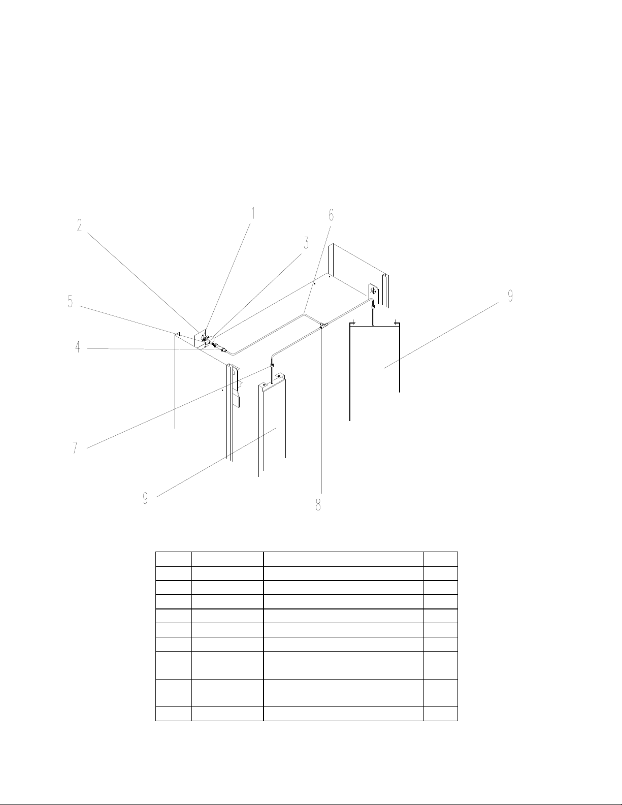
S
PARE PARTS AND
D
RAWINGS
WATER SYSTEM
Pos.
Code Description No.
1 M4x15 screw 2
2 566418031 Solenoid valve support 1
3 120800005 24 V “L.F.” Solenoid valve 1
4 Hose clamp 2
5 Rubber hose 1
6 385500002 Fired copper pipe 3
7 373000007
∅
8 bulkhead fitting
(art. 10465-8)
2
8 373000003 8x¼” T-fitting (art. 10240) 1
9 590518030 Steamer 280 2
ROTORBAKE Series Ovens - electric version - Page 56
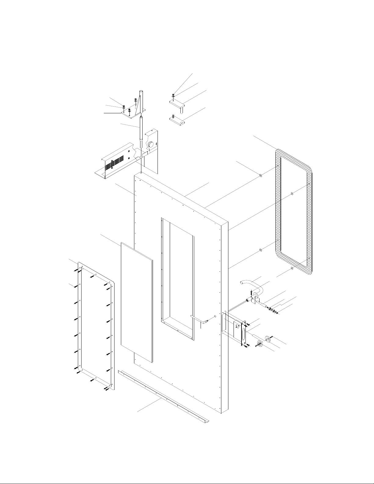
COMPLETE DOOR ASSEMBLY
24
23
22
21
4
3
2
1
5
5
7
8
9
10
12
13
11
16
17
18
15
14
20
19
25
26
27
28

ROTORBAKE Series Ovens - electric version - Page 57
COMPLETE DOOR ASSEMBLY
CODES
Pos.
Code Description Nr.
1 M4x13 self-threading screw 20
2 513016021 Glass frame 1
3 391516020 1097x385x10 Glass 1
4 562318030 Inside door panel 1
5 579118030 Outside door 1
6 308200001 Glass holder bushing 4
7 391518030 External glass 1160x448x6 1
8 747118030 Handle lever mechanism 1
9 M6x30 Allen screw 1
10 644118030 Bearing pin 1
11 331616000 609 ZZ SKF Bearing 2
12 Ø 8x21 Flat washer 2
13 M8 Nut 1
14 TSVP M6x20 Screw 4
15 588518030 Holding box 1
16 TE M5X10 Screw 4
17 629316020 Ring-nut 2
18 Ø6 Flexible washer 2
19 551618032 Internal handle 1
20 531818030 Gasket 1
21 664118300 Door pin 1
22 764818162 Door pin plate 1
23
∅8 Flexible washer
4
24 M8 nut 4
25 Fix plate 1
26 Hinge pin 1
27
∅8 Flexible washer
1
28 M8 Nut 1
ROTORBAKE Series Ovens - electric version - Page 58
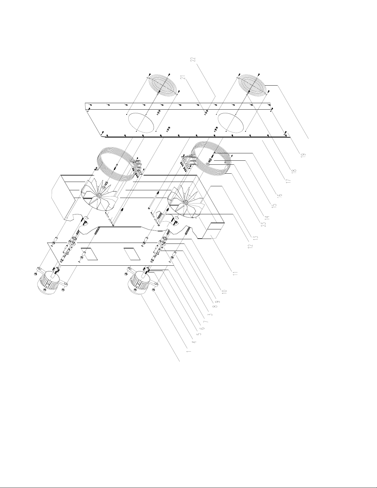
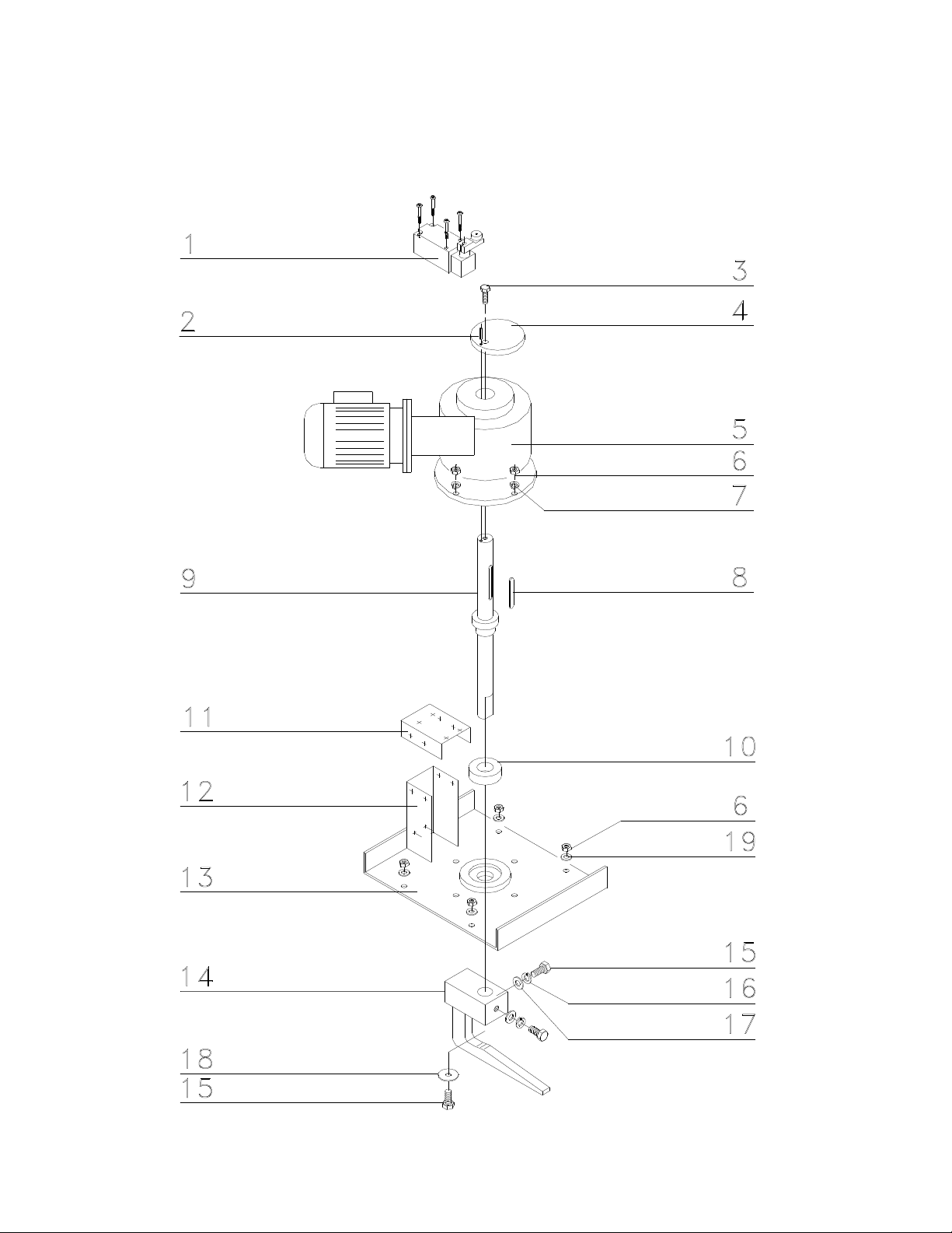
MOTOR ASSEMBLY

ROTORBAKE Series Ovens - electric version - Page 59
MOTOR ASSEMBLY
CODE
Pos. Code Description Nr.
1 M12 Nut 16
2 353000010 1088 HP 0,5 Motor type 2
3 615700001 Plate spacer 8
4 M5 Nut 6
5
∅5,3x10 Flat washer
6
6
∅5,1 Flexible grower washer
6
7 564018041 Motor plate 1
8 615700000 Flange spacer 6
9 625300000 Insulation flange 2
10 303000000
∅24 Teflon ring
2
11 773618030 Baking chamber 1
12 515718040 Central conveyor spacer 4
13 591500009 300x105 Straight-blade fan 2
14
∅13x55 Flat washer
2
15 393000001 Fan holding screw 2
16 M6x55 Screw 2
17 513018031 Central conveyor 1
18 M4x12 Self-threading screws 8
19 M4x12 Self-threading screws 26
20 531616020 Fan grid 2
21
∅8 Flat washer
4
22 M8 Nut 4
23 373500016 Heating element 2
ROTORBAKE Series Ovens - electric version - Page 60
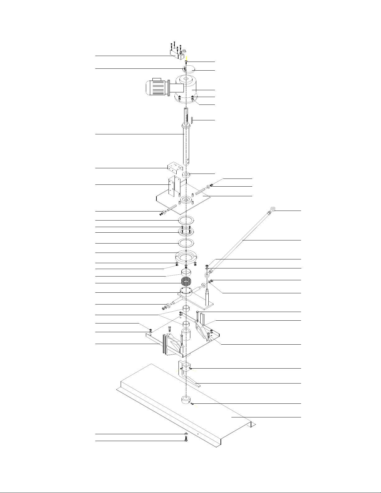
AUTOMATIC LIFT GROUP
33
35
25
29
13
6
21
20
6
34
19
13
30
32
27
30
31
28
26
25
25
24
24
16
16
17
18
15
12
11
9
1
2
8
13
14
10
6
23
22
7
6
5
4
3
36

ROTORBAKE Series Ovens - electric version - Page 61
AUTOMATIC LIFT GROUP
CODES
Pos. Code Description Nr.
1 124500001 FD 538 “PIZZATO” limit 1
2
∅4x20 Flange plug
1
3 M8x25 Allen screw 1
4 510518037 Gear motor cams 1
5 353000011 CRMI 40/50 Gear motor 1
6 M8 Nut 14
7
∅8 Flexible washer
4
8 8x5x60 Key 1
9 602618162 Gear motor shaft 1
10 331616000 40-68-19 Bearing 1
11 581018031 Limit stand 1
12 581018031 Limit stand 1
13
∅8 Flat washer
10
14 764818160 Reducer lift group plate 1
15 609 ZZ “SKF” Bearing 2
16 Roller 2
17 M5x10 Allen screws 4
18 629318301 Ring-nut 1
19 “IGUS” GSM-6065-30 Bearing 1
20 731618300 Lift group 1
21 15-32-7 Bearings 2
22 M16 Ball joint 2
23 583018300 Clevis 1
24 M10 Nut 3
25
∅10 Flat washer
4
26 T.E. M6x60 Screws 2
27 564818300 Cams plate 2
28 T.E. M6x30 Screw 2
29 76481861 Lift fix plate 1
30 M10x30 Thread grains 2
31 728418300 Automatic lift hook 1
32 735818300 Cart merry-go-round 1
33 629318300 Ring-nut 1
34 Bearing spacer 1
35 Screw T.E. M10x20 1
ROTORBAKE Series Ovens - electric version - Page 62
STANDARD LIFT GROUP

ROTORBAKE Series Ovens - electric version - Page 63
STANDARD LIFT GROUP
CODES
Pos. Code Description Nr.
1 124500001 FD 538 “PIZZATO” limit 1
2
∅4x20 Flexible plug
1
3 M8x25 Allen screw 1
4 510518037 Gear motor cams 1
5 353000011 CRMI 40/50 Gear motor 1
6 M8 Nut 8
7
∅8 Flexible washer
4
8 8x5x60 Key 1
9 602618030 Gear motor shaft 1
10 331616000 40-68-19 Bearing 1
11 581018031 Limit stand 1
12 581018031 Limit stand 1
13 564018030 Reducer group plate 1
14 728418030 Cart lift hook 1
15 T.E. M10x25 Screw 3
16
∅10 Flexible washer
2
17
∅10 Flat washer
2
18
∅10x28 Flat washer
1
19
∅8 Flat washer
4
ROTORBAKE Series Ovens - electric version - Page 64
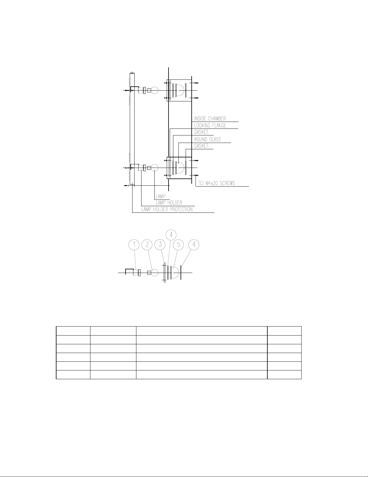
LAMP GROUP
Code Description Nr.
1 166400006 Ceramic lamp holder 2
2 146600011 24V 5J60W300° Lamp 2
3 325300000 Round crystals flange 2
4 331800007 Round crystals gasket 4
5 313300000 Round crystals light 2
ROTORBAKE Series Ovens - electric version - Page 65
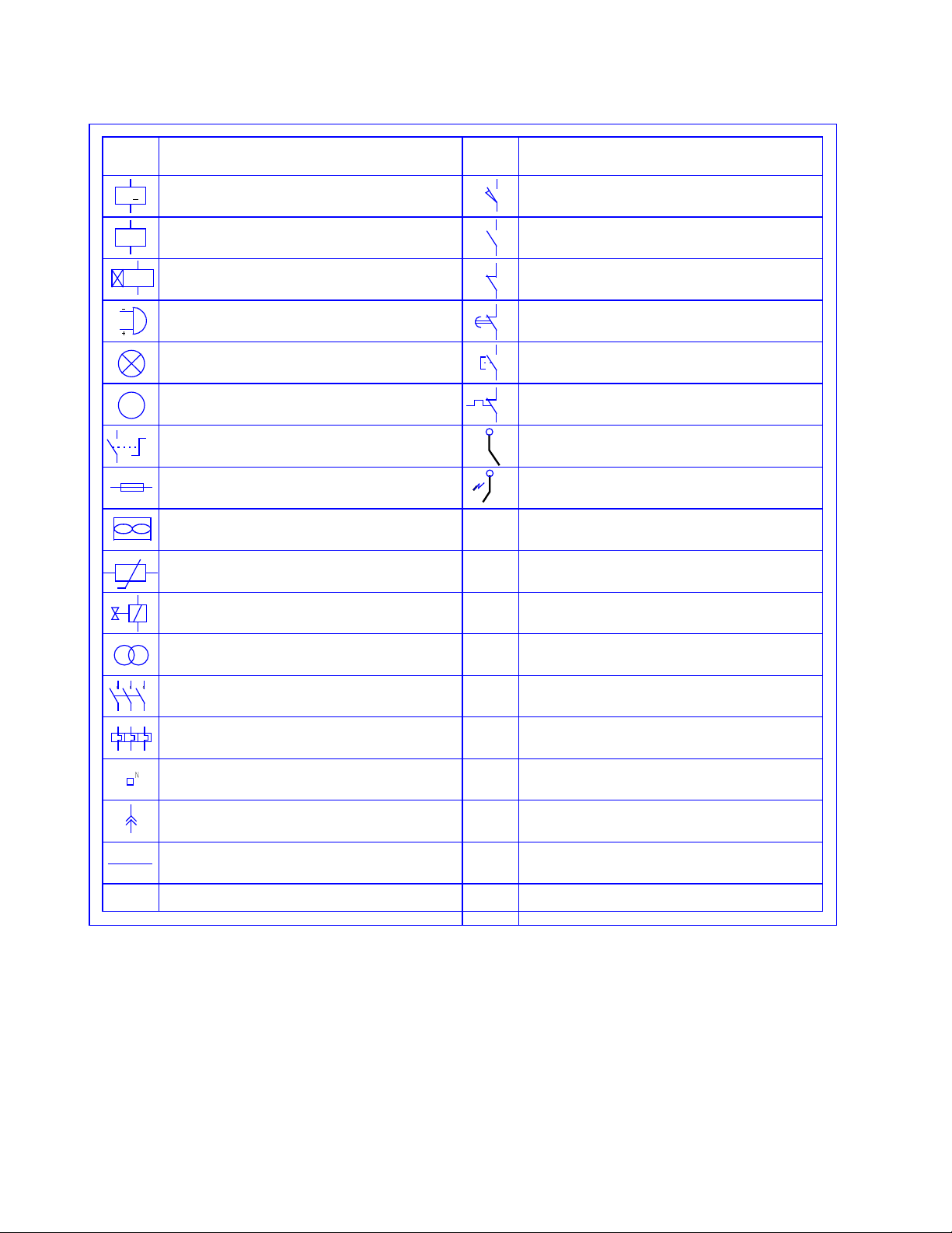
L
EGEND OF
S
YMBOLS
FLAME LIGHTER
NORMALLY - CLOSED THERMAL CONTACT
NORMALLY - OPEN CONTACT
DESCRIPTION
NORMALLY - OPEN CONTACT
NORMALLY - CLOSED CONTACT
DELAYED - CLOSURE CONTACT
BUTTON - CONTROL CONTACT
DESCRIPTION
CONTATCT AND/OR RELAY
BURNER ELECTRODE
ROTARY SWITCH
VENTILATION FAN
FUSE
BUZZER
LAMP
MOTOR
M
K
EH
SYMBOL
TIMER
KT
FLAME DETECTOR
SYMBOL
TERMINAL
TEMPERATURE PROBE
CONNECTOR TERMINAL
VOLTAGE TRANSFORMER
SINGLE - POLE WIRE
CONTACT
THERMAL RELAY
SOLENOID VALVE
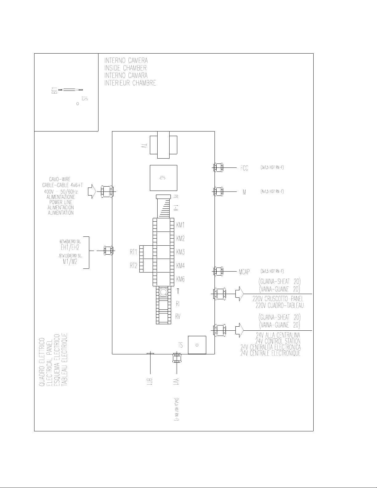
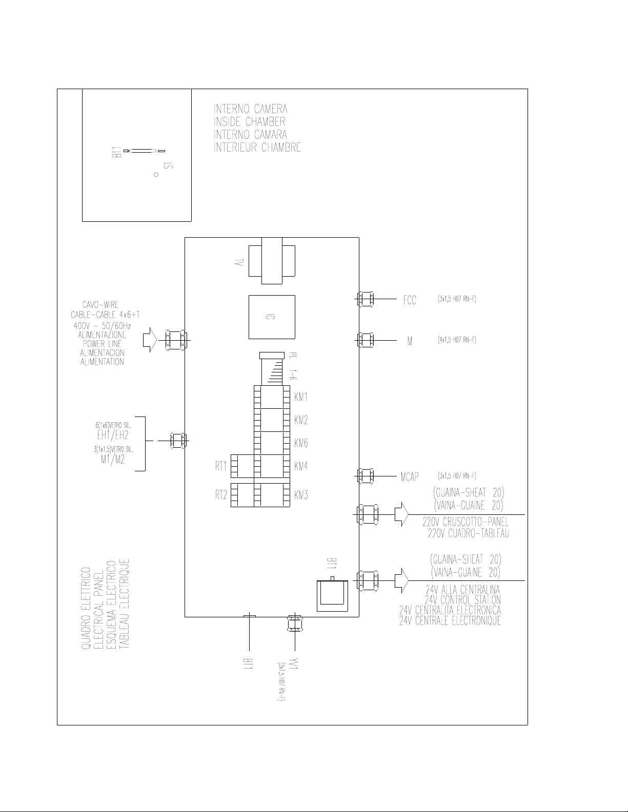
ROTORBAKE Series Ovens - electric version - Page 66
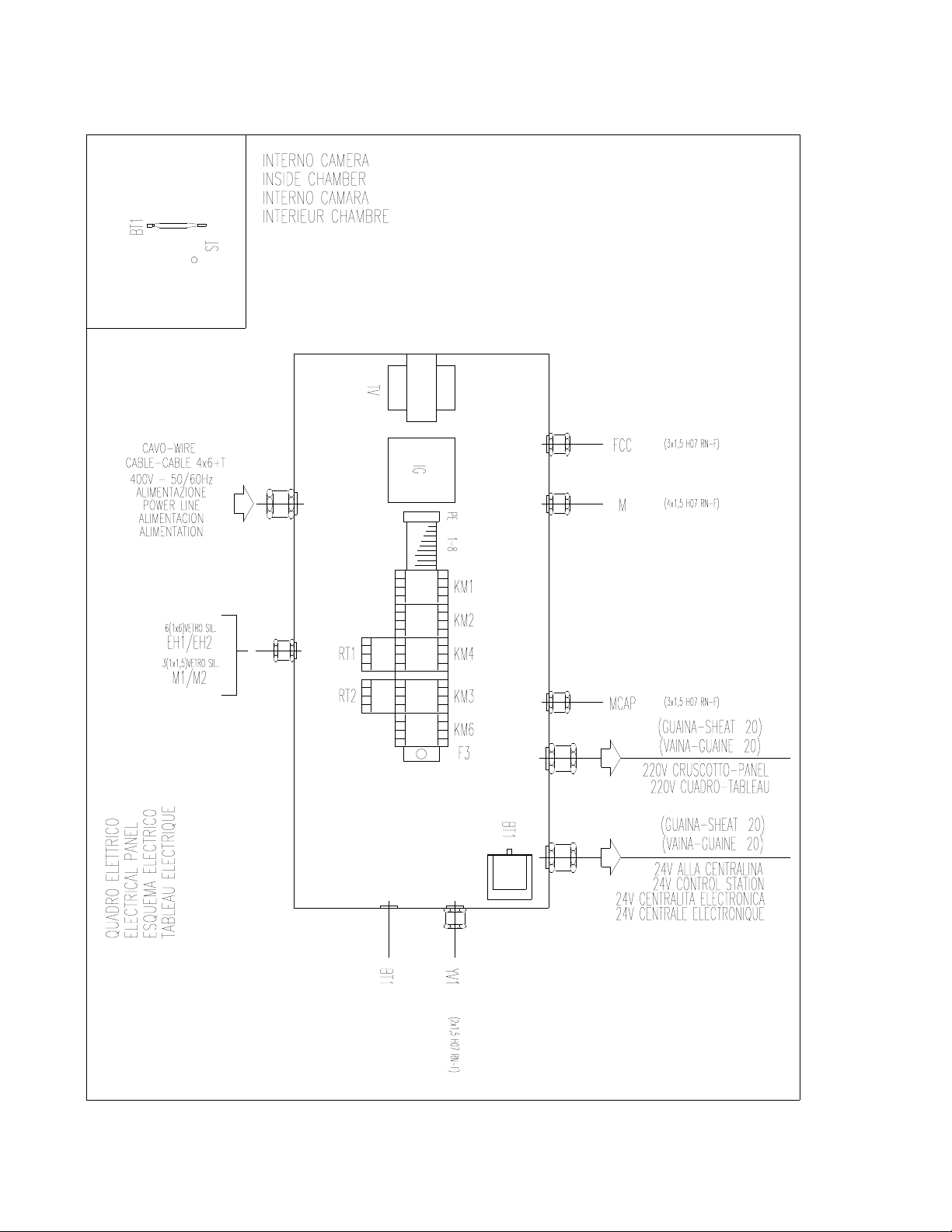
E
LECTRICAL
P
ANEL
L
AY
O
UT
E
XTRA
M
ODEL
D
IGITAL
C
ONTROL
O
VEN
ROTORBAKE Series Ovens - electric version - Page 67
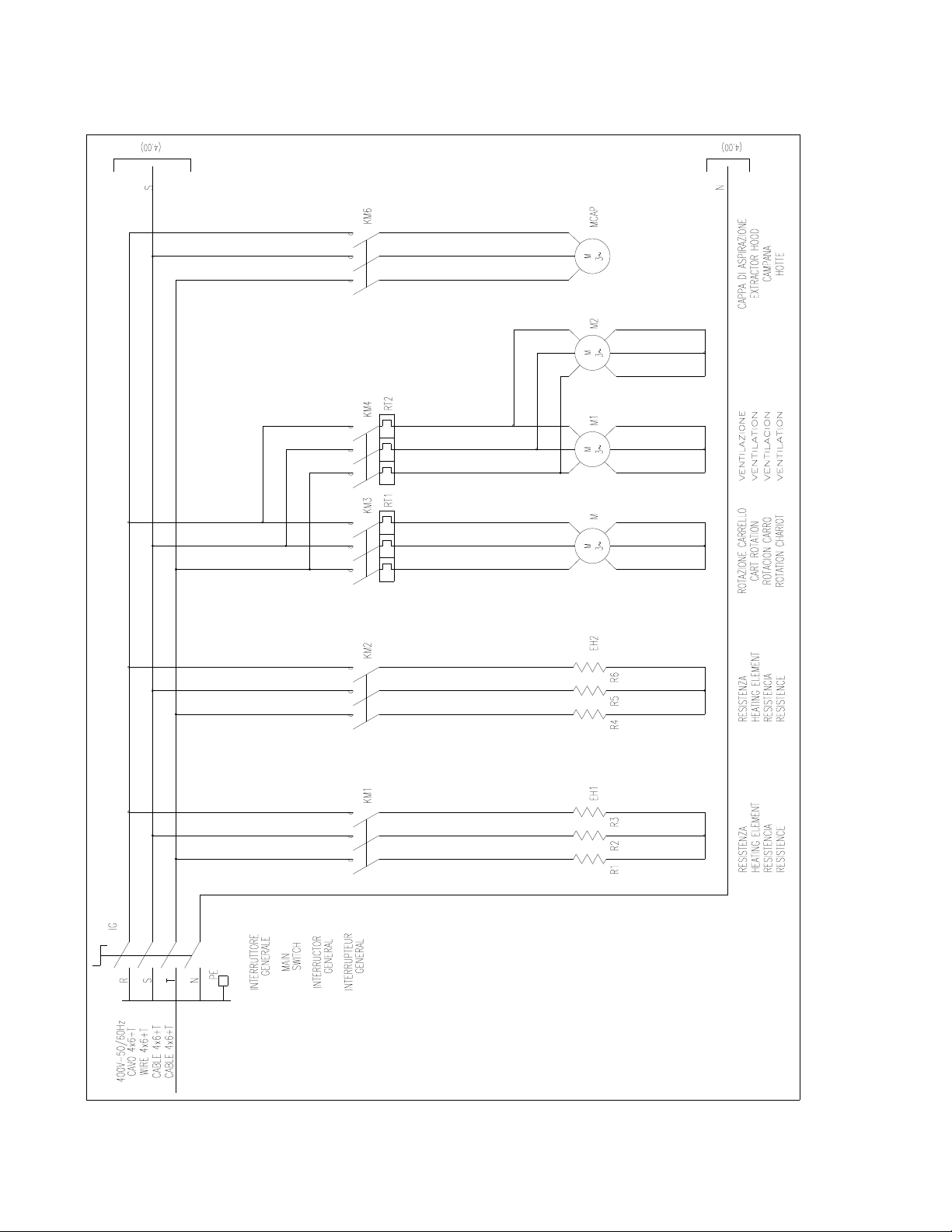
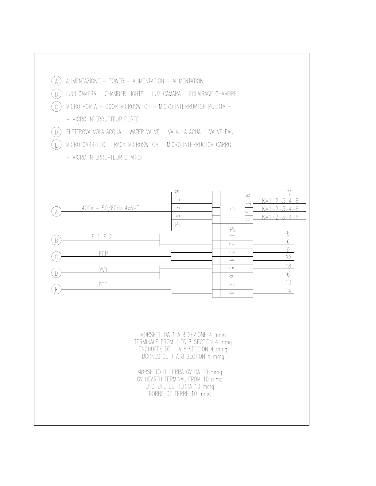
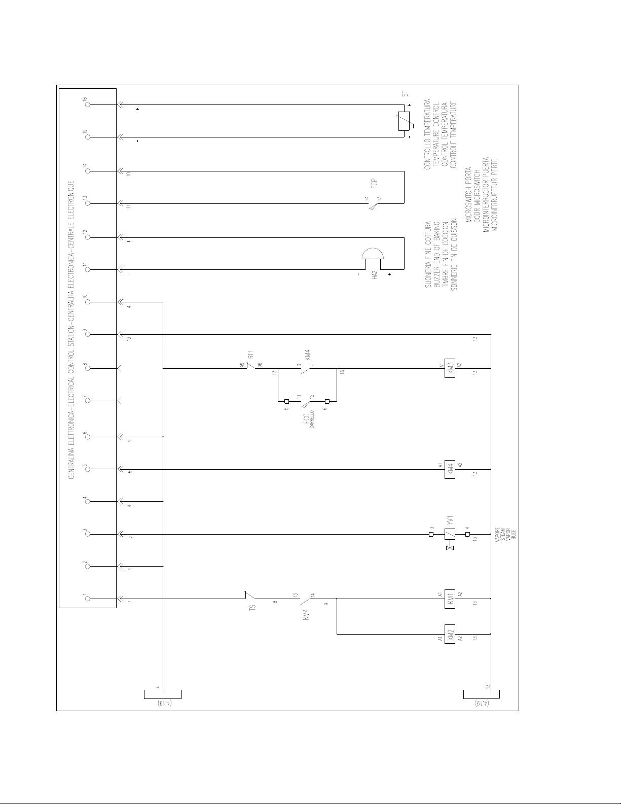
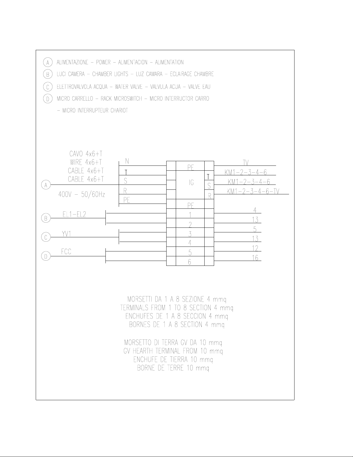
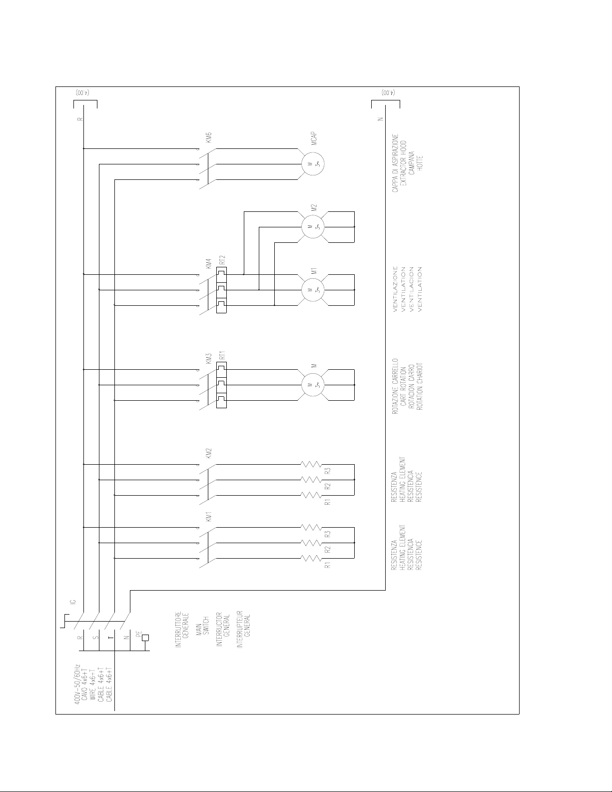
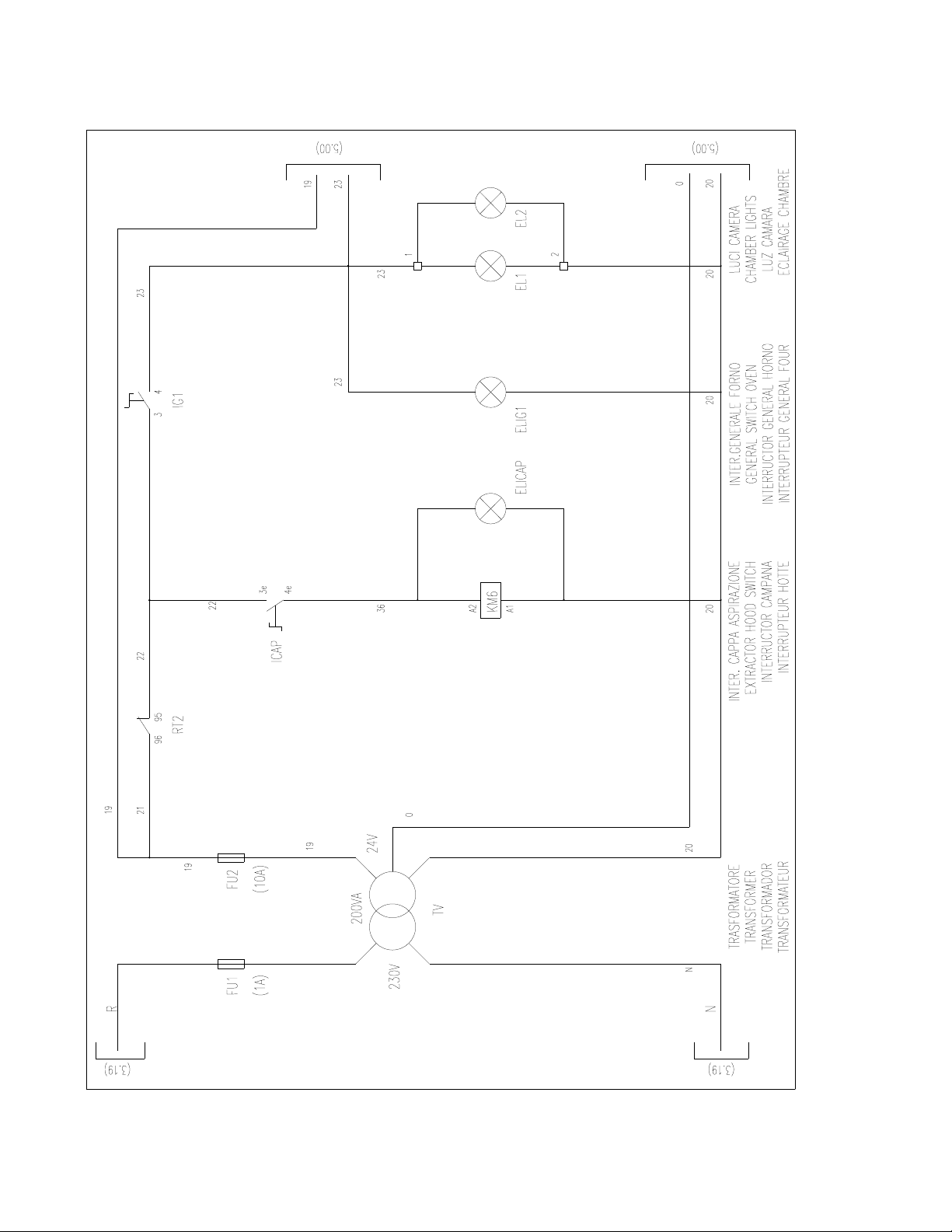
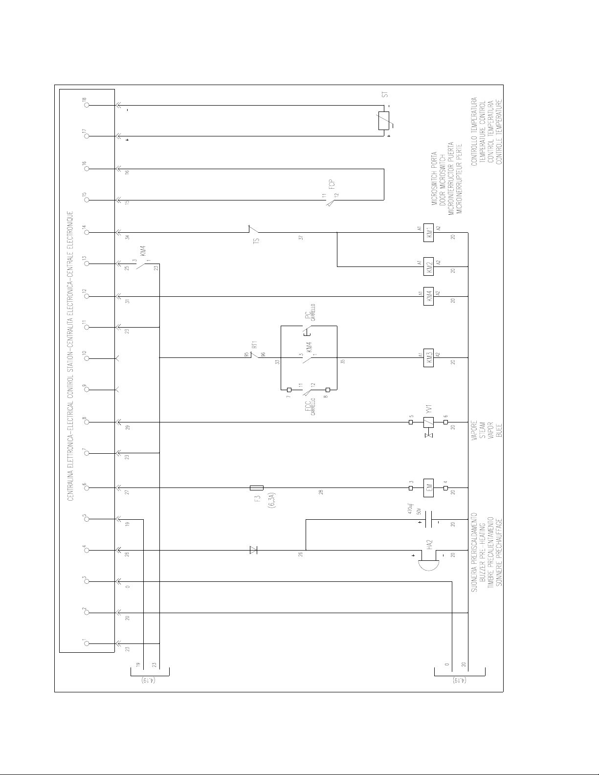
E
LECTRICAL
D
IAGRAM
E
XTRA
M
ODEL
D
IGITAL
C
ONTROL
O
VEN
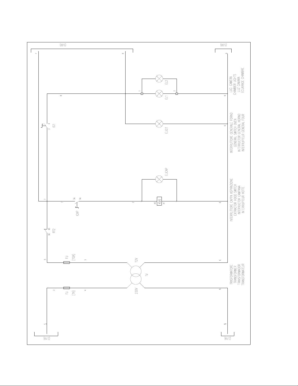
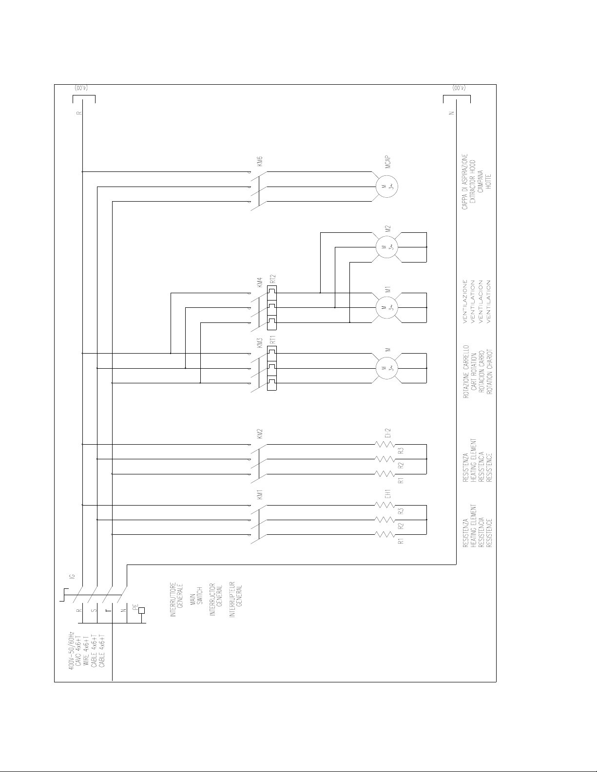
ROTORBAKE Series Ovens - electric version - Page 68
E
LECTRICAL
D
IAGRAM
E
XTRA
M
ODEL
D
IGITAL
C
ONTROL
O
VEN
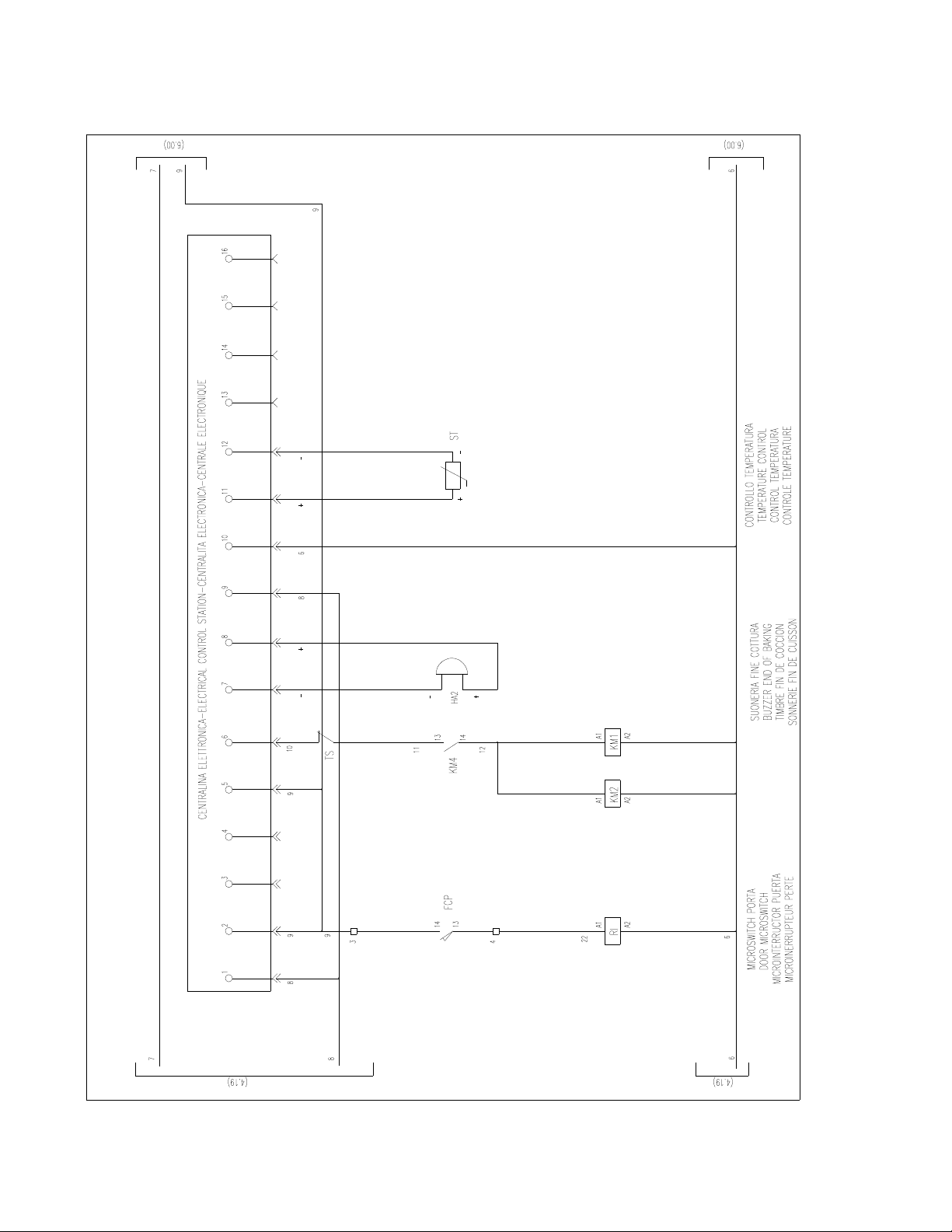
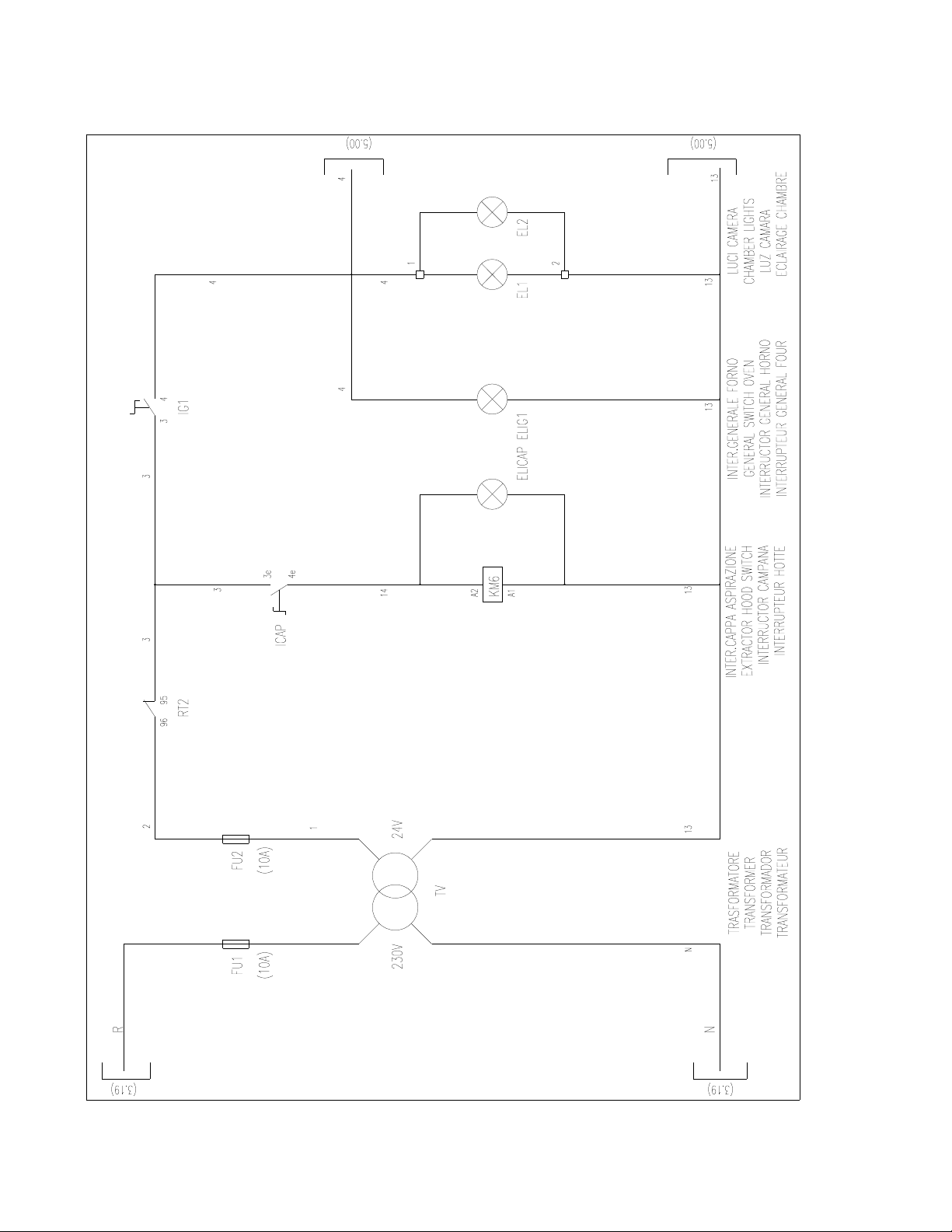
ROTORBAKE Series Ovens - electric version - Page 69
E
LECTRICAL
D
IAGRAM
E
XTRA
M
ODEL
D
IGITAL
C
ONTROL
O
VEN
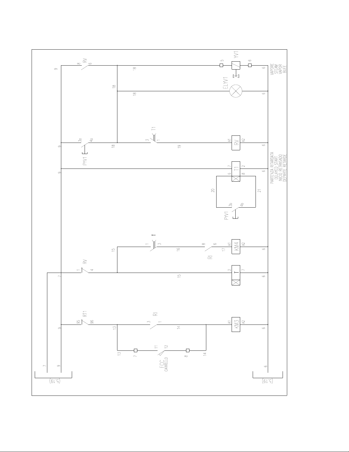
ROTORBAKE Series Ovens - electric version - Page 70
E
LECTRICAL
D
IAGRAM
E
XTRA
M
ODEL
D
IGITAL
C
ONTROL
O
VEN
ROTORBAKE Series Ovens - electric version - Page 71
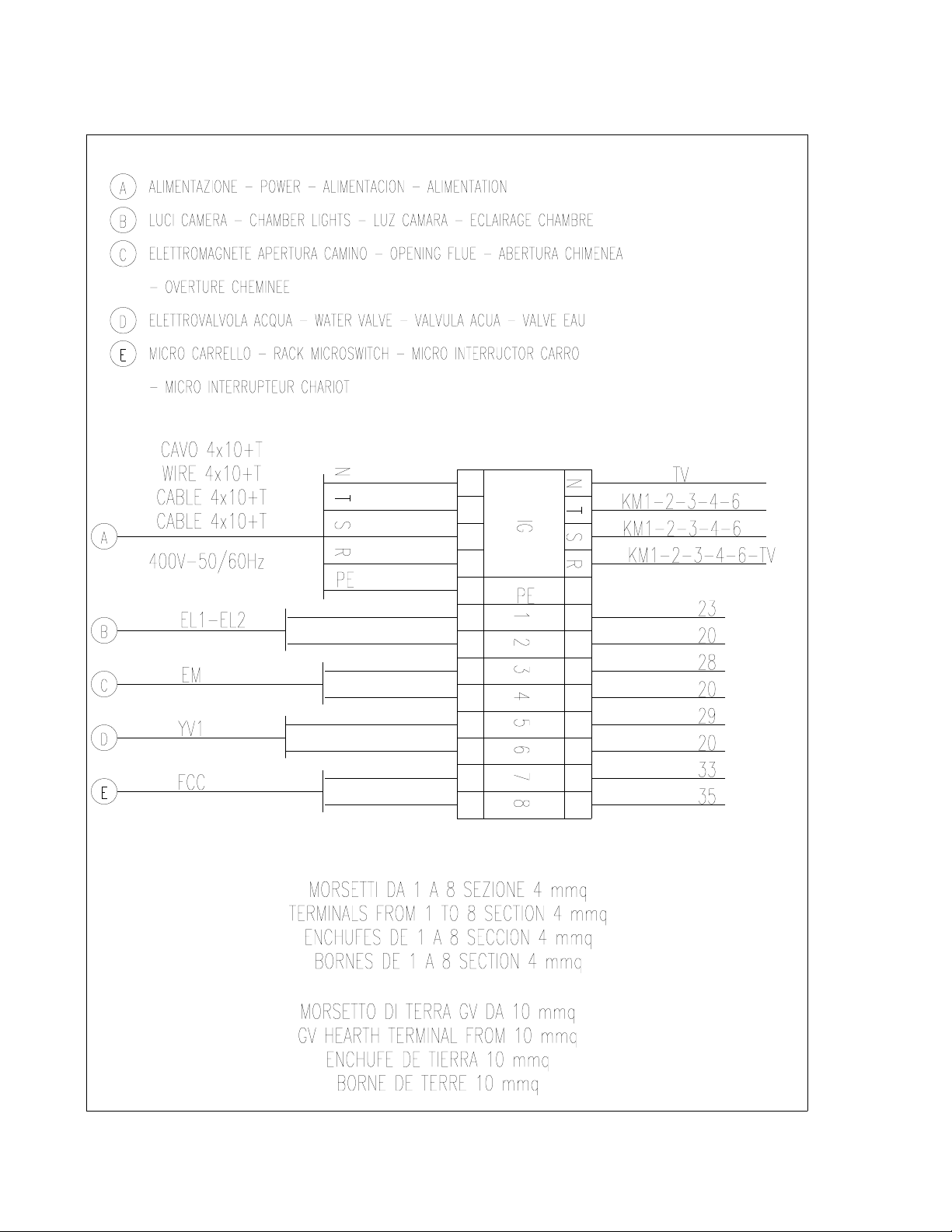
T
ERMINAL
B
OARD
E
XTRA
M
ODEL
D
IGITAL
C
ONTROL
O
VEN
ROTORBAKE Series Ovens - electric version - Page 72
E
LECTRICAL
D
IAGRAM
L
AY
O
UT
E
XTRA
M
ODEL
E
LECTRONIC
10P O
VEN
ROTORBAKE Series Ovens - electric version - Page 73
E
LECTRIC
D
IAGRAM
E
XTRA
M
ODEL
E
LECTRONIC
10P O
VEN
ROTORBAKE Series Ovens - electric version - Page 74
E
LECTRIC
D
IAGRAM
E
XTRA
M
ODEL
E
LECTRONIC
10P O
VEN
ROTORBAKE Series Ovens - electric version - Page 75
E
LECTRICAL
D
IAGRAM
E
XTRA
M
ODEL
E
LECTRONIC
10P O
VEN
ROTORBAKE Series Ovens - electric version - Page 76
T
ERMINAL
B
OARD
E
XTRA
M
ODEL
E
LECTRONIC
10P O
VEN
ROTORBAKE Series Ovens - electric version - Page 77
E
LECTRICAL
D
IAGRAM
L
AY
O
UT
E
XTRA
M
ODEL
E
LECTRONIC
100P O
VEN
ROTORBAKE Series Ovens - electric version - Page 78
E
LECTRICAL
D
IAGRAM
E
XTRA
M
ODEL
E
LECTRONIC
100P O
VEN
ROTORBAKE Series Ovens - electric version - Page 79
E
LECTRICAL
D
IAGRAM
E
XTRA
M
ODEL
E
LECTRONIC
100P O
VEN
ROTORBAKE Series Ovens - electric version - Page 80
E
LECTRIC
D
IAGRAM
E
XTRA
M
ODEL
E
LECTRONIC
100P O
VEN
ROTORBAKE Series Ovens - electric version - Page 81
T
ERMINAL
B
OARD
E
XTRA
M
ODEL
E
LECTRONIC
100P O
VEN
ROTORBAKE Series Ovens - electric version - Page 82
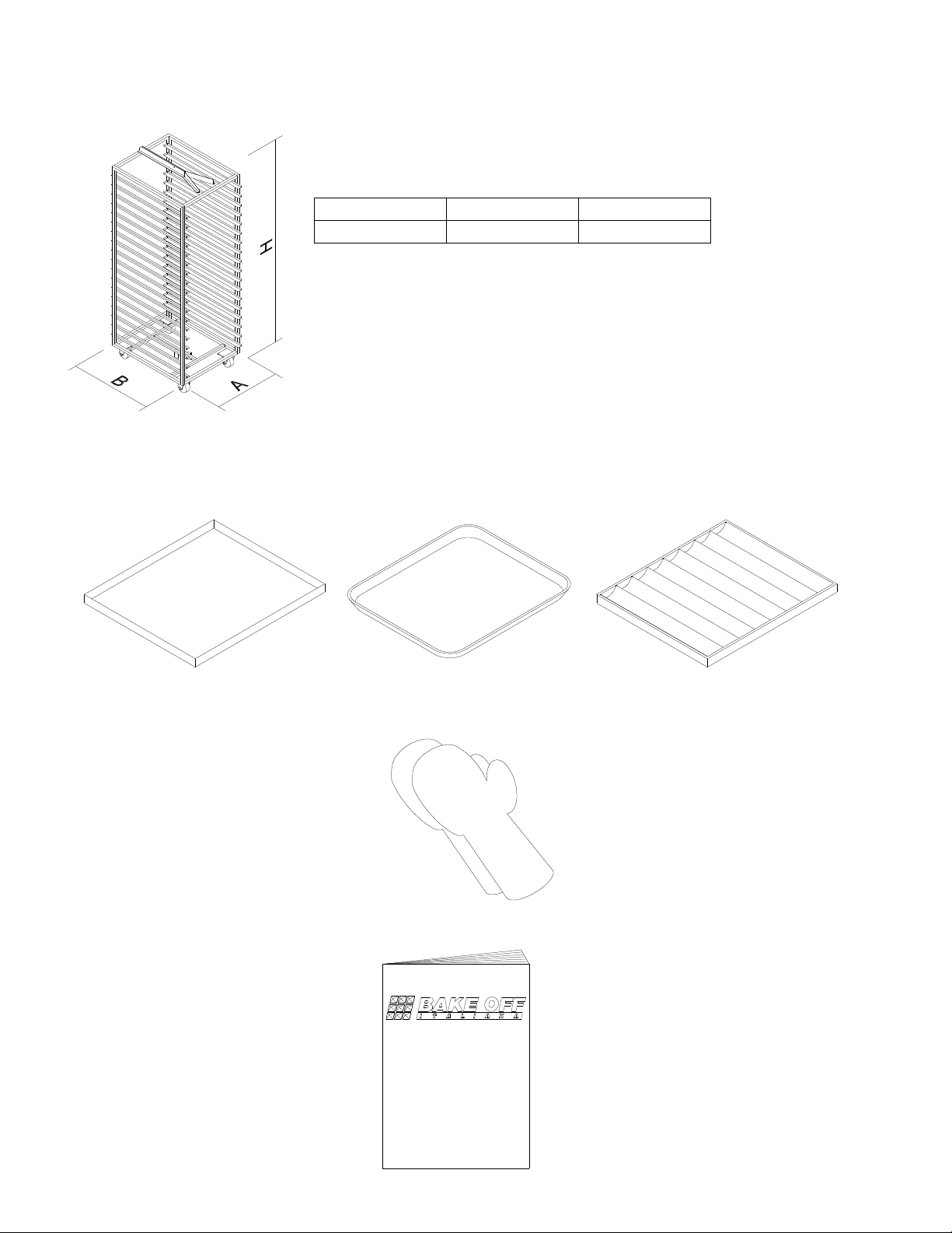
ACCESSORIES
RACK
A B H
860 817 1936
TRAYS
GLOVES
USER MANUAL
FLAT
FLAT WITH
WAVED
ROUND CORNERS
MANUALE DI ISTRUZIONE
PER L'INSTALLAZIONE
E PER L'USO
FORNI A GAS A CARRELLO ROTANTE
PER PASTICCERIA E PANETTERIA
Serie RotorBake T5
15 Teglie - Gas

ROTORBAKE Series Ovens - electric version - Page 83
N
OTES
As our Company is involved constantly in improvements of all our range of production, the aesthetic and
technical characteristics, the equipments and accessories could meet some changes.