Loading ...
Loading ...
Loading ...
100326-1 - 25 TON FULL BEAM LOG SPLITTER
OPERATION
24
Log Splitter Operation
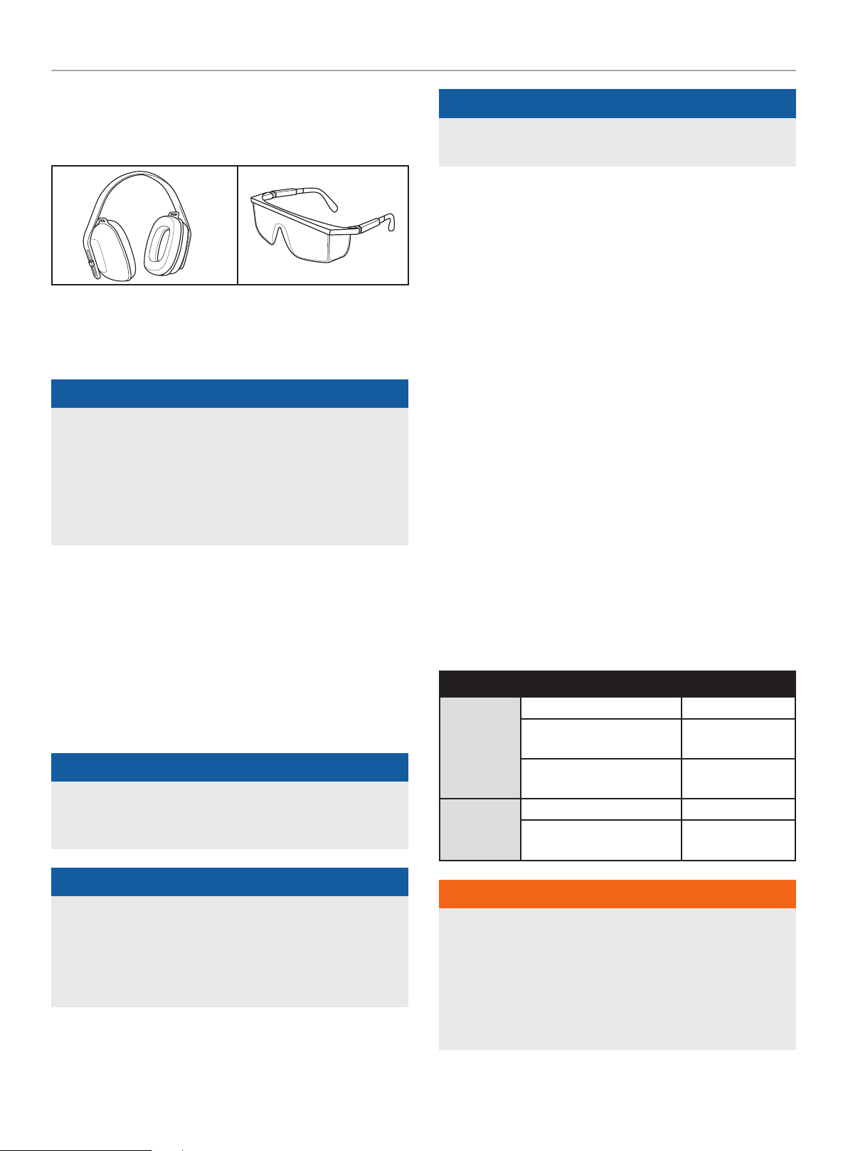
1. ALWAYS wear ear and eye protection, protective clothing and
safety gear.
2. Block tires and ensure support leg is secure to prevent
unintended movement of the log splitter during operation.
3. Set log splitter in either the horizontal or vertical position.
NOTICE
HORIZONTAL position is used for lighter logs that can easily be
loaded onto the beam.
VERTICAL position is used for light logs as well as heavy logs
that are difficult to load onto the beam.
Back injury can result from lifting logs onto the log splitter if
proper lifting techniques are not used.
4. Load a log onto the beam against the end plate
(MAX LOG LENGTH – 24 in. [61 cm]).
5. Make sure all limbs are clear of crush zones.
6. Push the control valve handle forward (towards the end plate)
to split the log.
7. Push the auto control valve handle backward to return the
wedge to its original position.
8. Clear the split wood from the work zone.
NOTICE
It is normal for the hydraulic fluid to appear foamy/frothy
during operation. This can be caused by agitated oil in the tank
collecting air.
NOTICE
If a log gets stuck, embedded or will not split completely,
push the control handle in the reverse direction and allow the
splitter to strip the log from the wedge.
ALWAYS keep hands clear of the log and wedge while it is
retracting.
NOTICE
The cylinder stroke is designed so the wedge stops
approximately 1.5 in. (3.8 cm) from the end plate.
Operation at High Altitude
The density of air at high altitude is lower than at sea level. Engine
power is reduced as the air mass and air-fuel ratio decrease.
Engine power and log splitter output will be reduced approximately
3½% for every 1000 ft. of elevation above sea level. This is a
natural trend and cannot be changed by adjusting the engine. At
high altitudes increased exhaust emissions can also result due to
the increased enrichment of the air fuel ratio. Other high altitude
issues can include hard starting, increased fuel consumption and
spark plug fouling.
To alleviate high altitude issues other than the natural power
loss, CPE can provide a high altitude carburetor main jet. The
alternative main jet and installation instructions can be obtained
by contacting our Technical Support Team. Installation instructions
are also available in the Technical Bulletin area of the CPE website.
The part number and recommended minimum altitude for the
application of the high altitude carburetor main jet is listed in the
table below.
In order to select the correct high altitude main jet it is necessary
to identify the carburetor model. For this purpose, a code is
stamped on the side of the carburetor. Select the correct high
altitude jet part number corresponding to the carburetor code
found on your particular carburetor.
Carb. Code High Alt. Jet Part Number Min. Altitude
16100-
Z811411-
00M3
16161-Z152010-00A1 Standard
16161-Z151810-00A0
3000-6000 ft.
(914.4-1828.8 m)
16161-Z151610-00A3
6000-8000 ft.
(1828.8-2438.4 m)
100730983-
0001
100073724 Standard
100092470
3281-9843 ft.
(1000-3000 m)
WARNING
Operation using the alternative main jet at elevations lower
than the recommended minimum altitude can damage the
engine. For operation at lower elevations, the originally
supplied standard main jet must be used. Operating the
engine with the wrong engine configuration at a given altitude
may increase its emissions and decrease fuel efficiency and
performance.
Loading ...
Loading ...
Loading ...