Loading ...
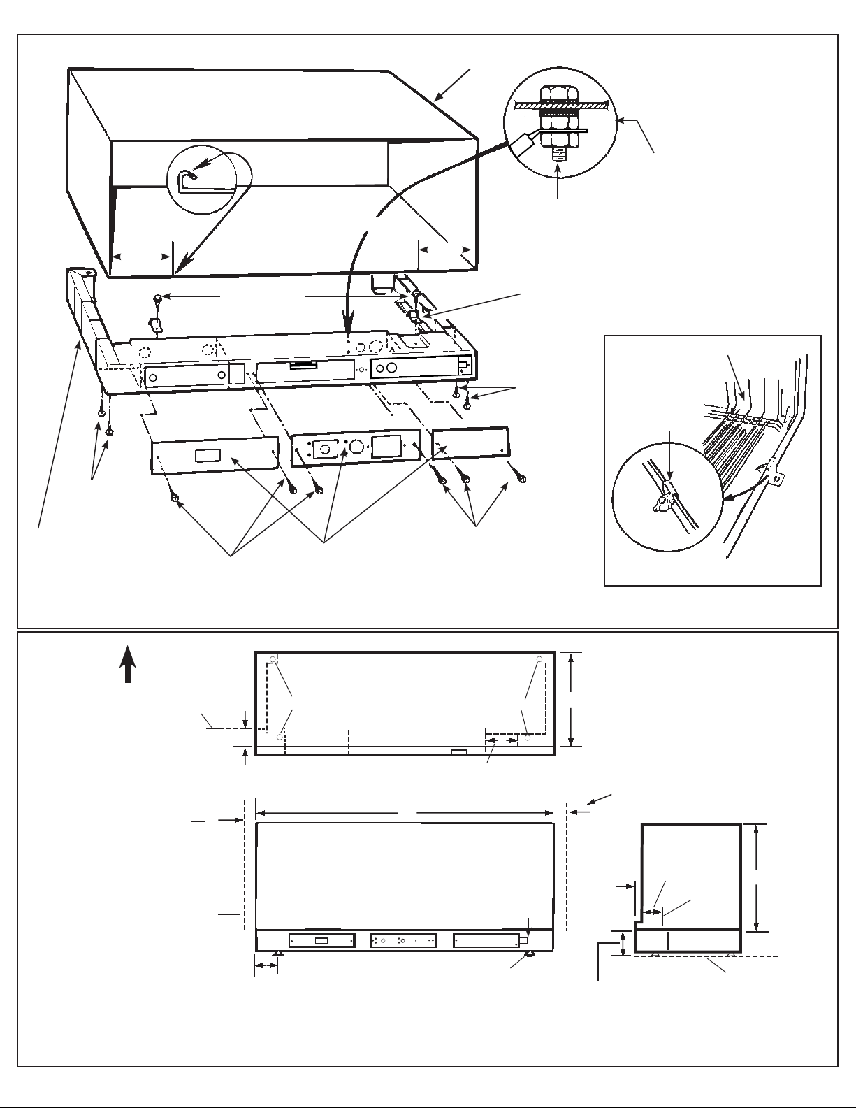
Leveling screw Leveling screw
Top view
13
3
/
4
”
3”
Bottom of sub-base is cut out on right end
to permit electrical circuit entry.
Finished
interior
wall
2
3
/8”
min.
Front view
42”
2”
3
1
/
2
”
Recommend 2” to
interior adjacent
wall both sides.
Interior adjacent
wall
Leveling screw
2”
16”
2
3
/8”
1
5
/
16
”
Side view
Interior
wall
3” min.,
adjustable
to 5”
Finished floor
See note
left side
OUTSIDE
NOTE: Remove knockouts from inside out. Knockouts (enclosure) 4 rear, 4 bottom.
Use as required for branch circuit wire entrance.
Green ground
screw (type C)
Mounting
clip for
metal case
type D
Type A
screws
Side channels are
adjustable from 13¾
3
to
2¾
3
in length by breaking of
sections of side channels.
Type C screws
Type A
screws
Access plates
5/32“ DIA. HOLES (SEE NOTE)
For securing type D clips
to sleeve using type A
screws
6"
6"
Type B screws
Mounting
clip for
molded case
type E
Molded case (RAB77)
NOTE: If the case does not have screw holes, 5/32” dia. holes must be drilled 6” from each side in the
front flange. (See insert)
Install ground screw from the
rear and secure from the inside
of the sub-base using a nut.
Secure branch circuit (or other)
ground wire using a second nut.
Recommend 2"
clearance to interior
adjacent wall both
sides.
Type C screws
Metal Case (RAB71)
Chaseway knockout
Loading ...
Loading ...
Loading ...