M
UL
TI
-ZONE
INVERTER
WIRED CONTROL FOR
AIR CONDITIONER
INSTALLATION MANUAL
SOPHIA
IMPORTANT NOTE:
Read this manual carefully before installing or operating
your wired remote control. Make sure to save this manual
for future reference.

Wall-Mounted Remote Control Wiring...............................1
Wall-Mounted Remote Control Installation ........................6
T able of Contents
1
Wall-Mounted Remote Control Wiring
WARNING
• The wiring should adapt to the wire control current.
Otherwise, electric leakage or overheating may occur
and result in fire.
• The specified cables must be used in the wiring. No
external force should be applied to the terminal.
Otherwise, the wire may be damaged and heating may
occur and result in fire.
CAUTION
• The shielded wire must be grounded.
•
The connecting cable shouldn't be longer than 20 m (65.5
ft).
• The remote control operates on a low-voltage circuit
loop. DO NOT connect a 220V or 380V cable to it.
• Make sure the configured tubes are 30-50 cm (12-20 ft)
or more apart.
• DO NOT employ an ohmmeter to detect the insulation
after wiring the remote control.
Wired control
2
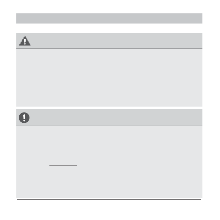
An overview of the wall-mounted remote control wire outlet
Top side wire outlet
Left side
wire outlet
Right side
wire outlet
Bottom side wire outlet
Fig. 1
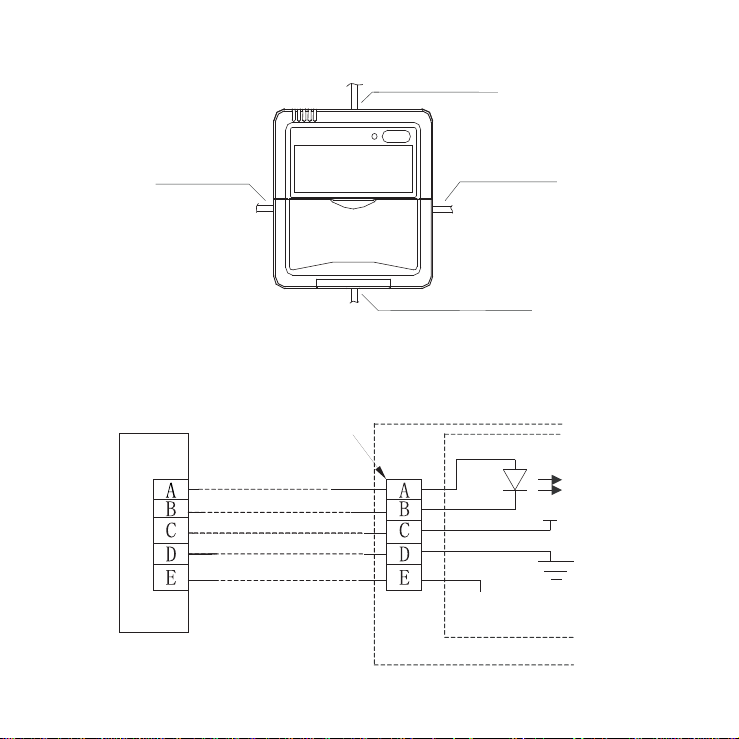
1. Wiring diagram
Refer to the following diagram to wire the wall-mounted
remote control to the indoor unit.
5-Core shield cable
Wired j
oint, 5p
Infrared p
ipe
RUN
GND
+5V
Indoor u
nit switchboard
Indoor unit
Fig. 2
3
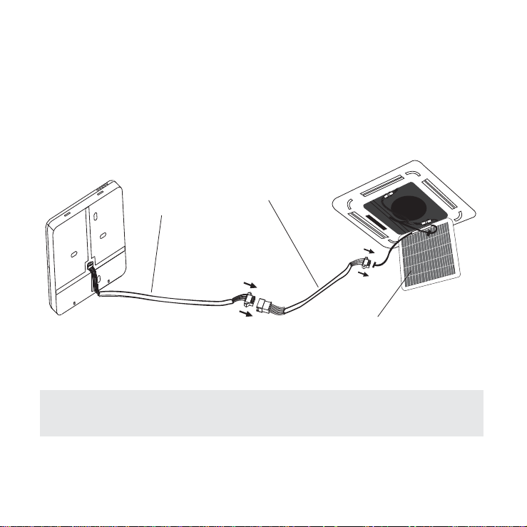
2. Installation Diagram
Connect the wire from the display panel of the indoor
unit to a connecting cable. Then connect the other side
of the connecting cable to the remote control.
5-core wire
The connective wires group
Front grille
Fig. 3
NOTE: Be sure to reserve a length of the connecting wire
for periodic maintenance.
4
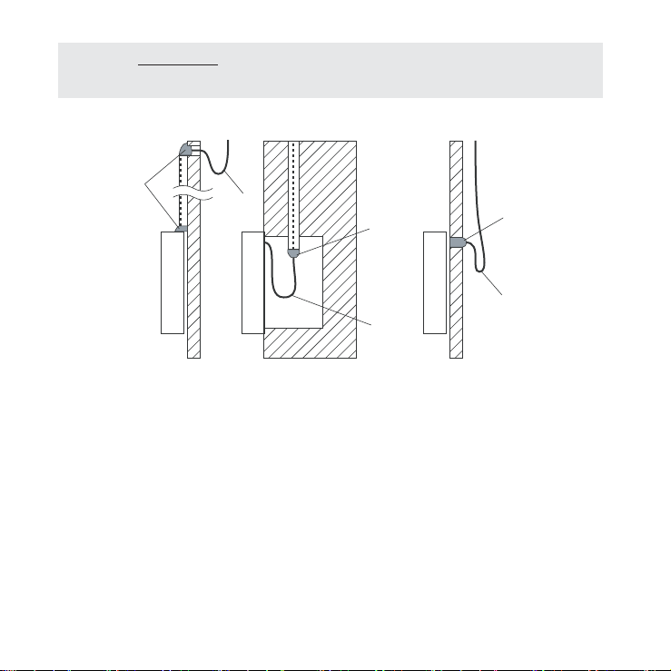
NOTE: DO NOT allow water to enter the remote control.
Use the trap and putty to seal the wires.
Putty
Putty
Putty
Trap
Trap
Trap
Fig. 4
a. For exposed mounting, cut holes on four of the
sides according to Fig. 5.
b. For shielded wiring, please refer to Fig. 6.
5
Cut three holes
for wire outlet
Fig. 5
Embedded switch box wiring
Wiring hole
Wiring through the wall
Wall hole and wiring hole
Diameter of wall hole: Φ 2cm
Fig. 6
Cut one hole
for wire outlet
6
Wall-Mounted Remote Control Installation
W ARNING
DO NOT operate the unit with wet hands, as this could
lead to electrical shock.
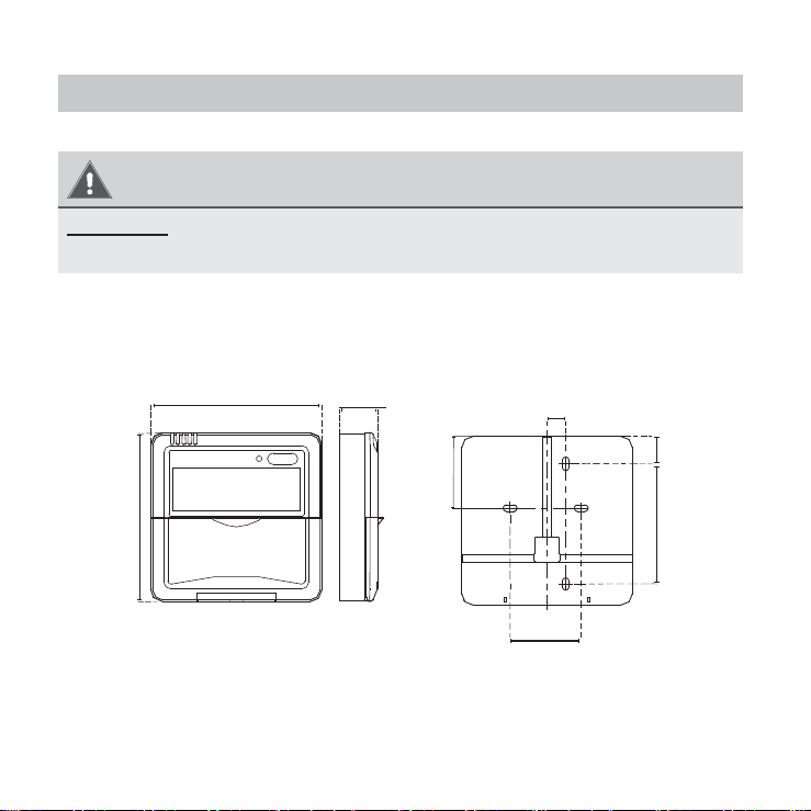
Remote Control Dimensions
120 mm
(4.7 in)
120 mm
(4.7 in)
21 mm
(0.8 in)
51.1 mm
(2 in)
13.1 mm
(0.5 in)
85.5 mm
(3.3 in)
50 mm
(1.9 in)
19.5 m m
19.5 mm
(0.7 in)
Fig. 7
7
Preparation before Installation
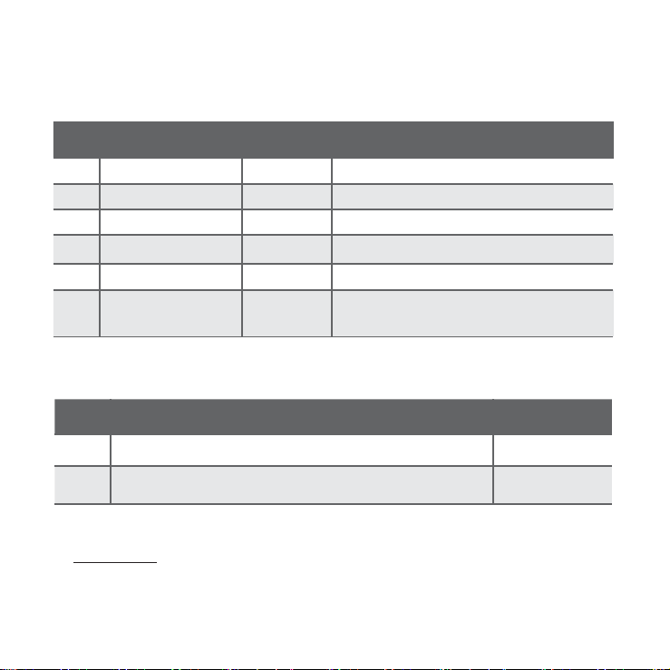
1. Be sure you have the following parts:
Table 1
No Name Quantity Remarks
1 Remote control 1
2 Screws 3
M4x20 (for mounting on the wall)
3 Anchors 3
For mounting on the wall
4
Screws 2
M4x25 (for mounting on switch box)
5 Plastic screw bars 2 For fixing on the switch box
6
The connective
wires group
1 Optional
2. Prepare the following tools:
Table 2
No Name
Quantity
1
Switch box
1
2
Wiring tube (insulating sleeve and tightening screw)
1
3. Select installation location:
DO NOT install the remote control near flammable liquids
or gases such as gasoline or hydrogen sulfide. This will
create a fire hazard.
8
Installation Method
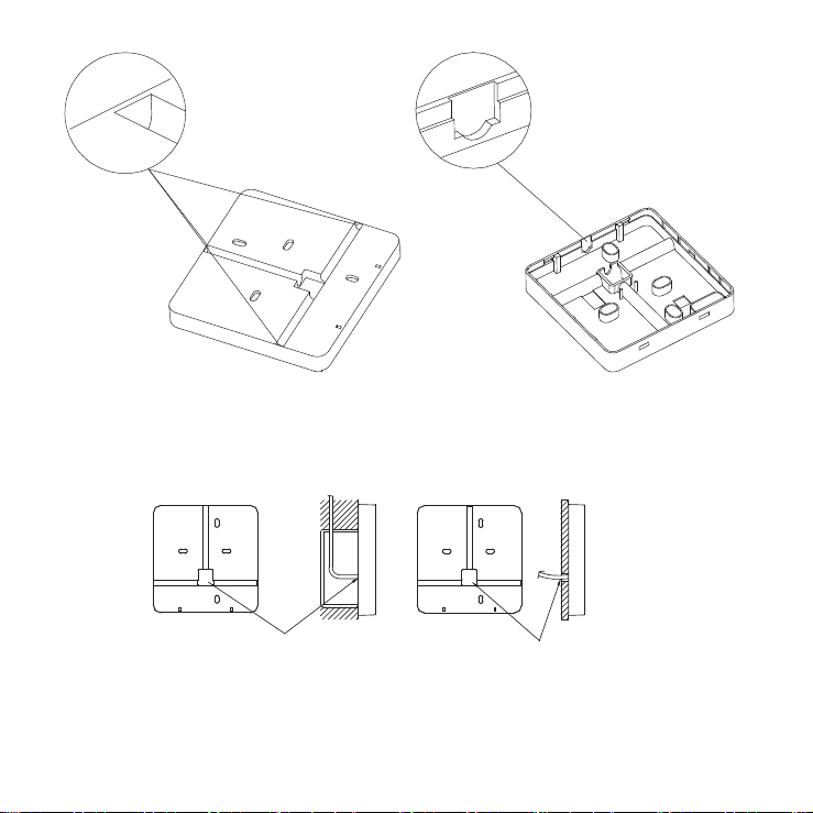
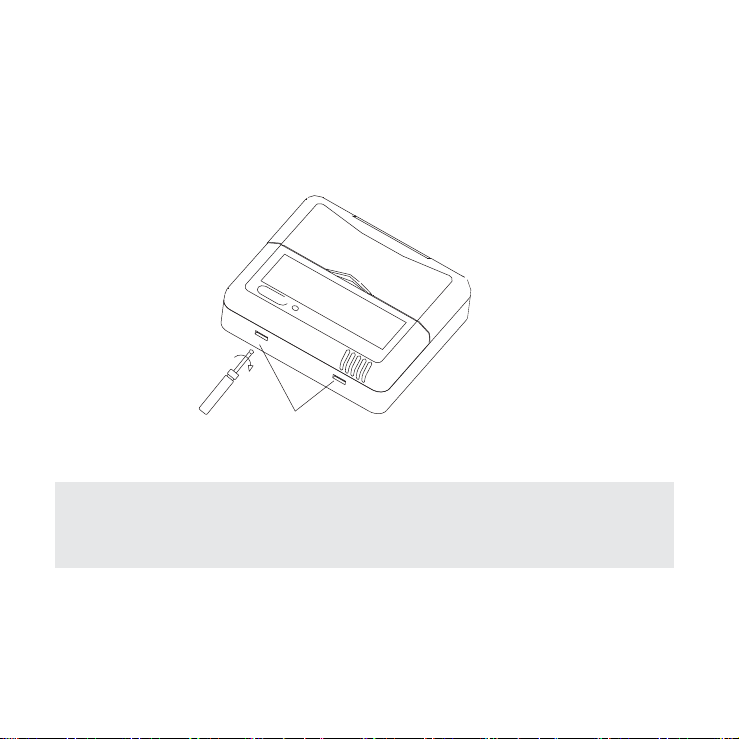
1. Remove the top panel of the remote control:
Insert a screwdriver into the two slots at the bottom of
the remote control to pop off the top panel.
Slots
Fig. 8
NOTE: The
printed circuit board (PCB) is mounted in the
upper part of the r
emote contr
ol. Be careful not to damage
the boar
d with the scr
ewdriver.
2. Mount the back plate of the remote control:
a. For exposed mounting, fasten the back plate to the
wall with 3 screws (M4×20) and anchors.
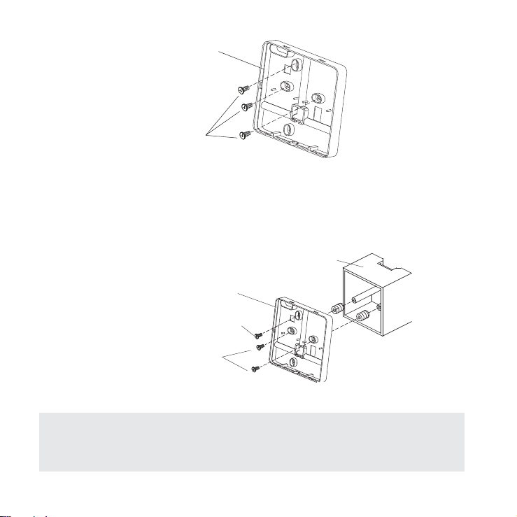
9
Back plate
Screws (M4×20)
Fig. 9
b. For flush mounting, fasten the back plate to the switch
box with 2 screws (M4×25) and fasten the back plate
to the wall with 1 screw (M4×20).
Switch box
Back plate
Screw (M4×20)
Screws (M4×25)
Fig. 10
NOTE: Place the unit on a flat surface. Be careful not
to distort the back plate of the remote control by over-
tightening the screws.
10
3. Set the time and date:
The remote control has a small, built-in battery that
allows the time and date to be set. This allows the
remote control to keep time even during a power
outage. When the unit displays an incorrect time and
date, the batteries need to be replaced.
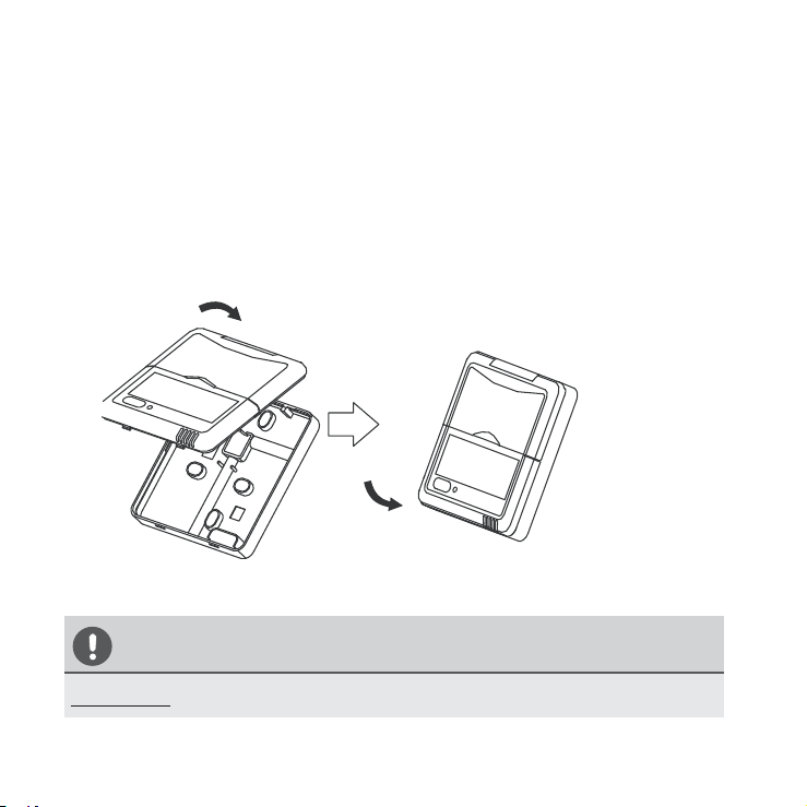
4. Reattach the top panel of the remote control:
Fig. 11
CAUTION
DO NOT clamp the wires when reattaching the top panel.

QSXI-005AEN
The design and specifications are subject to change without
prior notice for product improvement. Consult with the
sales agency or manufacturer for details.