Loading ...
Loading ...
Loading ...
6
• If the windows are large, use additional window bracket
(B4) to cover your window opening, extending it to the
required length, then securing it with the locking wing nut
supplied (g. 3).
max 33ft~
12
3
3
8
9
8
9
6
4
Click
5
• Insert and lock the accessory for window bracket (B1) al-
ready attached to the air exhaust hose, into the slot of the
window bracket (g. 4).
• At the other end, be sure hose adapter’s tab is straight up
(like the 12 position on a clock) as shown in g. 5.
max 33ft~
12
3
3
8
9
8
9
6
4
Click
5
max 33ft~
12
3
3
8
9
8
9
6
4
Click
5
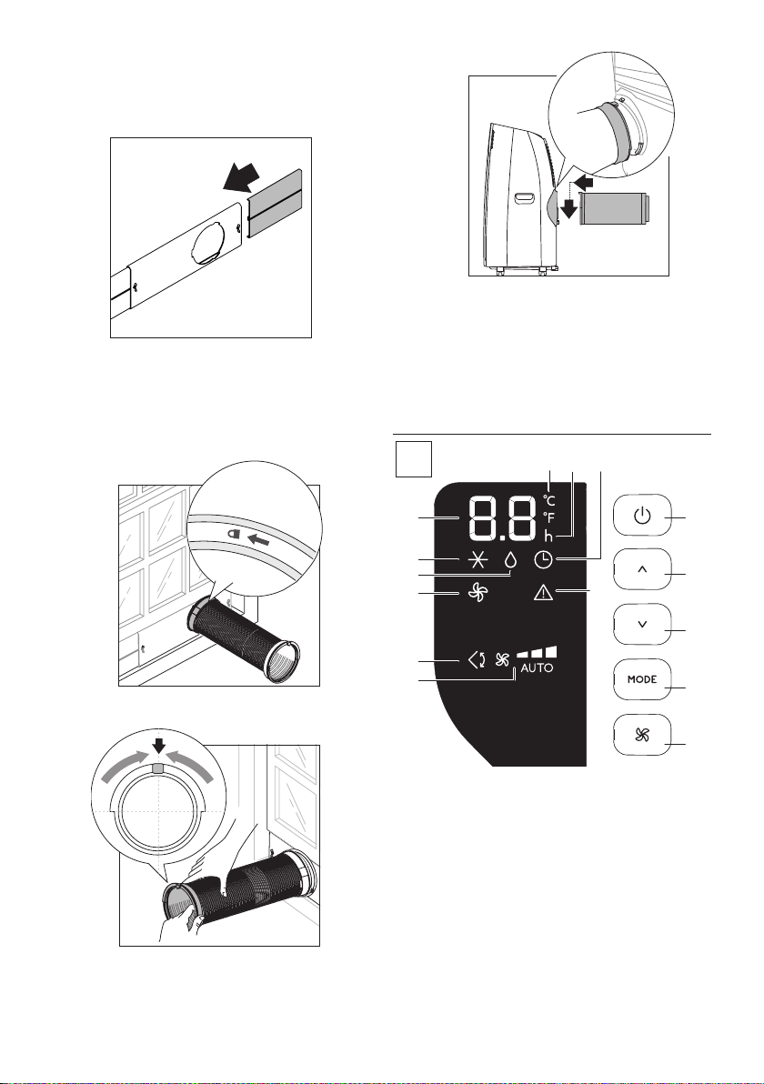
• Attach assembled hose to the back of the air conditioner
(g. 6).
max 33ft~
12
3
3
8
9
8
9
6
4
Click
5
SLIDING WINDOWS
• Thanks to the locking wing nut, it’s possible to use the win-
dow bracket also for sliding windows. Position the hole of
the window bracket in the lower corner to allow for correct
installation of the exhaust hose.
OPERATING FROM THE CONTROL PANEL
C1
C13
C11
C10
C9
C8
C7
C6
C14C15
C3
C4
C2
C5
C12
DESCRIPTION OF THE CONTROL PANEL (C)
C1. ON/STAND-BY (on/o) key
C2. Mode selection key (air conditioning dehumidifying, fan)
C3. Increase key
C4. Decrease key
C5. Air ow selection key (MIN/MED/MAX/AUTO)
C6. Air conditioning symbol
C7. Dehumidifying symbol
C8. Fan symbol
C9. Swing symbol
C10. Air ow indicator
C11. Alarm symbol
C12. Set temperature display, programmed on/o time
C
Loading ...
Loading ...
Loading ...