
INDOOR PRESERVATION
Refrigerators, Freezers and Wine Storage
KRP / KRB / KRC / KFC / KWC / KRW
Installation Manual
READ THESE INSTRUCTIONS CAREFULLY AND COMPLETELY
BEFORE INSTALLING OR USING YOUR APPLIANCE TO REDUCE
THE RISK OF FIRE, BURN HAZARD, OR OTHER INJURY. KEEP
THIS MANUAL FOR FUTURE REFERENCE.
Do not store or use gasoline or other flammable vapors and liquids in the vicinity of
this or any other appliance.
Installation and service must be performed by a qualified installer or service agency.
DO NOT REPAIR, REPLACE OR REMOVE ANY PART OF THE APPLIANCE UNLESS
SPECIFICALLY RECOMMENDED IN THE MANUAL. IMPROPER INSTALLATION,
SERVICE OR MAINTENANCE CAN CAUSE INJURY OR PROPERTY DAMAGE. REFER
TO THIS MANUAL FOR GUIDANCE. ALL OTHER SERVICING SHOULD BE DONE BY A
QUALIFIED TECHNICIAN.
INSTALLER: LEAVE THIS MANUAL WITH THE OWNER OF THE APPLIANCE.
HOMEOWNER: RETAIN THIS MANUAL FOR FUTURE REFERENCE.
IF THE INFORMATION IN THIS MANUAL IS NOT FOLLOWED
EXACTLY, A FIRE OR EXPLOSION MAY RESULT CAUSING PROPERTY
DAMAGE, PERSONAL INJURY, OR DEATH.
EN
SAFETY DEFINITIONS
©2018 Hestan Commercial Corporation
DANGER. THIS INDICATES INFORMATION AND WARNINGS WHICH,
IF NOT OBSERVED, MAY COMPROMISE PERSONAL SAFETY OR DAMAGE
THE APPLIANCE.
DANGER OF ELECTROCUTION. THIS INDICATES INFORMATION AND
WARNINGS OF AN ELECTRICAL NATURE WHICH, IF NOT OBSERVED,
MAY COMPROMISE PERSONAL SAFETY OR DAMAGE THE APPLIANCE.
THIS HIGHLIGHTS GENERAL INFORMATION AND WARNINGS AND
INDICATES THAT DAMAGE TO THE APPLIANCE OR PROPERTY MAY
OCCUR AS A RESULT OF NOT OBSERVING THIS WARNING.
TABLE OF CONTENTS
EN
©2018 Hestan Commercial Corporation
1
When properly cared for, your Hestan appliance will provide safe, reliable service for many
years. When using this appliance, basic safety practices must be followed as outlined below.
IMPORTANT: Save these instructions for the local Utility Inspector’s use.
INSTALLER: Please leave these Installation Instructions with the owner.
OWNER: Please retain these Installation Instructions for future reference.
This appliance is NOT designed for installation in manufactured (mobile) homes or
recreational park trailers. Do NOT install this appliance outdoors.
SAFETY PRECAUTIONS - BEFORE YOU BEGIN
ELECTRICAL SHOCK HAZARD
Disconnect power before installing or servicing appliance. Failure to do
so can result in death or electrical shock.
ELECTRICAL GROUNDING
• This appliance must be grounded. Grounding reduces the risk of electric shock in the
event of a short circuit. Read the ELECTRICAL and WATER CONNECTIONS sections
of this manual for complete instructions.
• DO NOT ground to a gas pipe.
• DO NOT use an extension cord with this appliance.
• DO NOT have a fuse in the NEUTRAL or GROUNDING circuit. A fuse in the NEUTRAL
or GROUNDING circuit could result in an electrical shock.
1 SAFETY PRECAUTIONS - BEFORE YOU BEGIN
2 MODEL NUMBERS
3
RATING LABEL
3 REGULATORY / CODE REQUIREMENTS
4 IMPORTANT CHILD SAFETY
4
LOCATION AND INSTALLATION
29 REQUIRED VENTILATION
30
TESTING AND INITIAL START-UP
REFRIGERATION MODELS
FREEZER MODELS
Model No.
Model No.
Description
Description
MODEL NUMBERS
©2018 Hestan Commercial Corporation
2
KRPR36 Bottom Mount Refrigerator, Top Compressor, Pro, Right Hinged, 36"
KRPL36 Bottom Mount Refrigerator, Top Compressor, Pro, Left Hinged, 36"
KRPR36-XX Bottom Mount Refrigerator, Top Compressor, Pro, Color, Right Hinged, 36"
KRPL36-XX Bottom Mount Refrigerator, Top Compressor, Pro, Color, Left Hinged, 36"
KRBR36 Bottom Mount Refrigerator, Bottom Compressor, Right Hinged, 36"
KRBL36 Bottom Mount Refrigerator, Bottom Compressor, Left Hinged, 36"
KRBR36-OV Bottom Mount Refrigerator, Bottom Compressor, Overlay, Right Hinged, 36"
KRBL36-OV Bottom Mount Refrigerator, Bottom Compressor, Overlay, Left Hinged, 36"
KRBR36-XX Bottom Mount Refrigerator, Bottom Compressor, Color, Right Hinged, 36"
KRBL36-XX Bottom Mount Refrigerator, Bottom Compressor, Color, Left Hinged, 36"
KRCR24 Refrigerator Column, Right Hinged, 24"
KRCL24 Refrigerator Column, Left Hinged, 24"
KRCR24-OV Refrigerator Column, Overlay, Right Hinged, 24"
KRCL24-OV Refrigerator Column, Overlay, Left Hinged, 24"
KRCR24-XX Refrigerator Column, Color, Right Hinged, 24"
KRCL24-XX Refrigerator Column, Color, Left Hinged, 24"
KRCR30 Refrigerator Column, Right Hinged, 30"
KRCL30 Refrigerator Column, Left Hinged, 30"
KRCR30-OV Refrigerator Column, Overlay, Right Hinged, 30"
KRCL30-OV Refrigerator Column, Overlay, Left Hinged, 30"
KRCR30-XX Refrigerator Column, Color, Right Hinged, 30"
KRCL30-XX Refrigerator Column, Color, Left Hinged, 30"
KFCR24 Freezer Column, Right Hinged, 24"
KFCL24 Freezer Column, Left Hinged, 24"
KFCR24-OV Freezer Column, Overlay, Right Hinged, 24"
KFCL24-OV Freezer Column, Overlay, Left Hinged, 24"
KFCR24-XX Freezer Column, Color, Right Hinged, 24"
KFCL24-XX Freezer Column, Color, Left Hinged, 24"
KFCR30 Freezer Column, Right Hinged, 30"
KFCL30 Freezer Column, Left Hinged, 30"
KFCR30-OV Freezer Column, Overlay, Right Hinged, 30"
KFCL30-OV Freezer Column, Overlay, Left Hinged, 30"
KFCR30-XX Freezer Column, Color, Right Hinged, 30"
KFCL30-XX Freezer Column, Color, Left Hinged, 30"
EN
©2018 Hestan Commercial Corporation
3
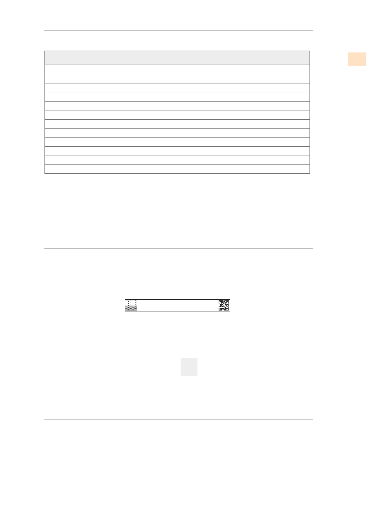
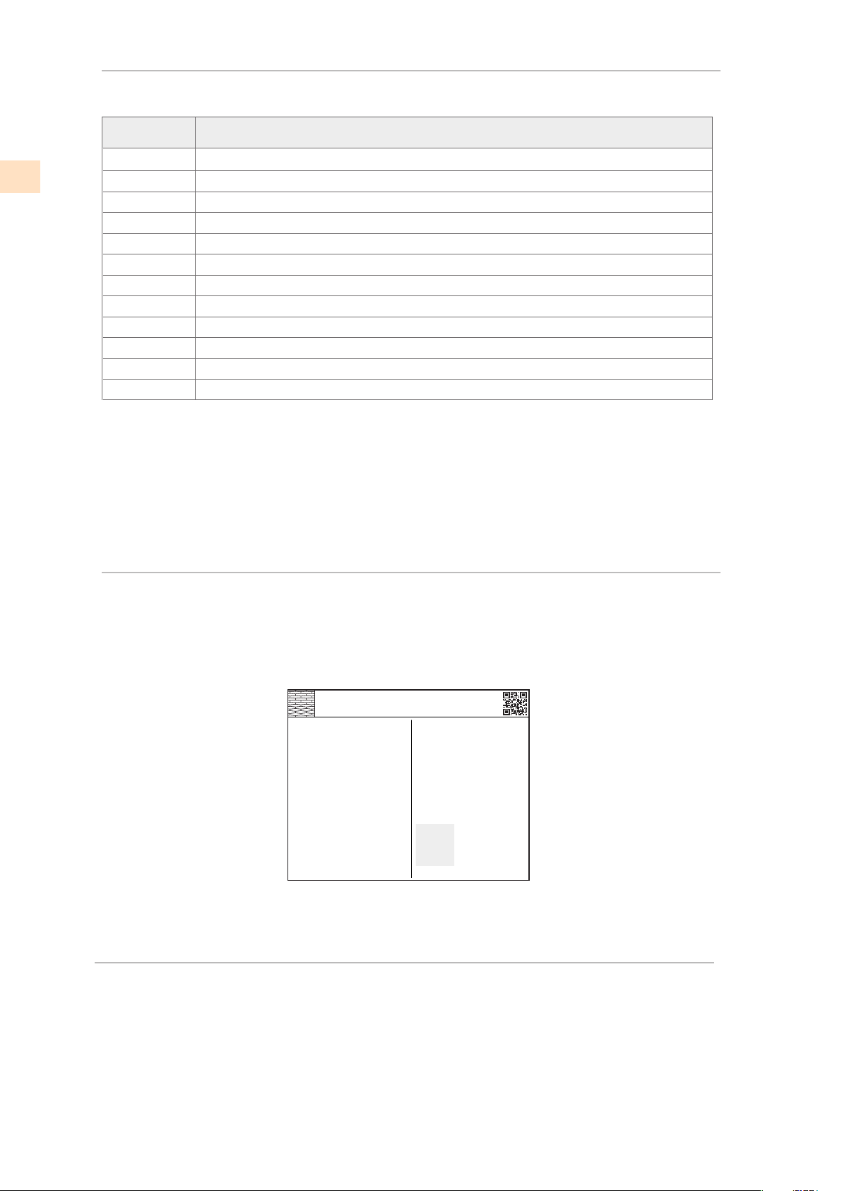
Hestan appliance such as the model and serial number and
electrical rating.
The rating label is located on the inside wall of the refrigerator.
TYPICAL RATING LABEL
RATING LABEL
MODEL NUMBERS
The rating label contains important information about your
REGULATORY / CODE REQUIREMENTS
Installation of this appliance must be made in accordance with local codes. In the
absence of local codes, this unit should be installed in accordance with the National Electrical
Code and local codes.
This appliance must be electrically grounded in accordance with local codes or in the absence
of local codes with the National Electrical Code
ANSI/NFPA 70
, or Canadian Electrical code
CSA C22.1
.
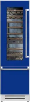
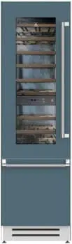
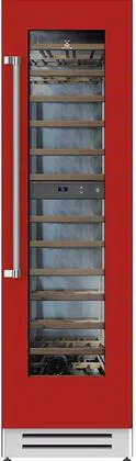
WINE MODELS
Model No. Description
(continued)
NOTE: -XX indicates color model.
-BK for Stealth - Black
-YW for Sol - Yellow
-PP for Lush - Purple
-GG for Pacific Fog - Graphite Gray
-WH for Froth - White
-OR for Citra - Orange
-BU for Prince - Blue
-RD for Matador - Red
-BG for Tin Roof - Burgundy
-GR for Grove - Green
-TQ for Bora Bora - Turquoise
KWCR24 Wine Column, Right Hinged, 24"
KWCL24 Wine Column, Left Hinged, 24"
KWCR24-OV Wine Column, Overlay, Right Hinged, 24"
KWCL24-OV Wine Column, Overlay, Left Hinged, 24"
KWCR24-XX Wine Column, Color, Right Hinged, 24"
KWCL24-XX Wine Column, Color, Left Hinged, 24"
KRWR24 Refrigerator with Wine, Right Hinged, 24"
KRWL24 Refrigerator with Wine, Left Hinged, 24"
KRWR24-OV Refrigerator with Wine, Overlay, Right Hinged, 24"
KRWL24-OV Refrigerator with Wine, Overlay, Left Hinged, 24"
KRWR24-XX Refrigerator with Wine, Color, Right Hinged, 24"
KRWL24-XX Refrigerator with Wine, Color, Left Hinged, 24"
ozFridge Gas Fill Charge
Quantité de Gaz Réfrigerateur
Freezer Gas Fill Charge
Quantité de Gaz Congélateur
Total Absorbed Current
Courant Absorbée Totale
Voltage
Tension
Frequency
Frequence
Refrigerant Gas Type
Type de Gaz Rèfrigerant
MODEL
Made in Italy
CODE
SER.NO./N° SERIE
3186660
ETL LISTED
CONFORMS TO
ANSI/UL STD 250
CERTIFIED TO CAN/CSA
STD C22.2 NO.63
A
V
Hz
HESTAN COMMERCIAL CORP.
ANAHEIM, CA - USA
KRP36
7
0
1
115
60
R134a
FI24RC-RO
XXXXXXXXXXX
EN

PREPARATION
IMPORTANT CHILD SAFETY
LOCATION AND INSTALLATION
©2018 Hestan Commercial Corporation
4
DANGER: Risk of child entrapment. Before you throw away your old
refrigerator or freezer:
• Take off the doors
• Leave the shelves in place so that children may not easily climb
inside.
w: 650 mm (25 5/8”) h: 2260 mm (89”) d: 800 mm (31 1/2”)
w: 800 mm (31 1/2”) h: 2260 mm (89”) d: 800 mm (31 1/2”)
230 kg (507 lb)
30” Models
36” Models
275 kg (606 lb)
w: 950 mm (37 3/8”) h: 2260 mm (89”) d: 800 mm (31 1/2”)
295 kg (650 lb)
PACKAGED DIMENSIONS AND WEIGHTS
ELECTRICAL AND WATER SUPPLY
PROVIDED INSTALLATION ACCESSORIES
TOOLS
Before moving the refrigerator, protect any finished flooring to prevent damage.
Make sure that power can be provided to the location selected.
24” Models
The following tools are needed for the installation of the dishwasher:
• Phillips screw driver
• Drill and drill bits
• 3/4” open-end or adjustable wrench
• 1/2” wrench or socket
The following pages provide the necessary information for proper installation of the refrigerator
and are arranged as follows:
• Technical data.
• Installation cutout dimensions, required clearances and mounting instructions.
• Electrical requirements and connections.
• Initial power-up and testing.
STEPS FOR INSTALLATION
110V 60Hz 15a
From 7.3 TO 73 PSI
3/4” female attachment
Customized panel mounting kit (included with -OV models only)
Anti-tip kit
Lateral/side connecting kit
4 mm (1/8”) allen wrench
Electrical requirement:
Potable water supply pressure:
Water supply tube:
EN
©2018 Hestan Commercial Corporation
5
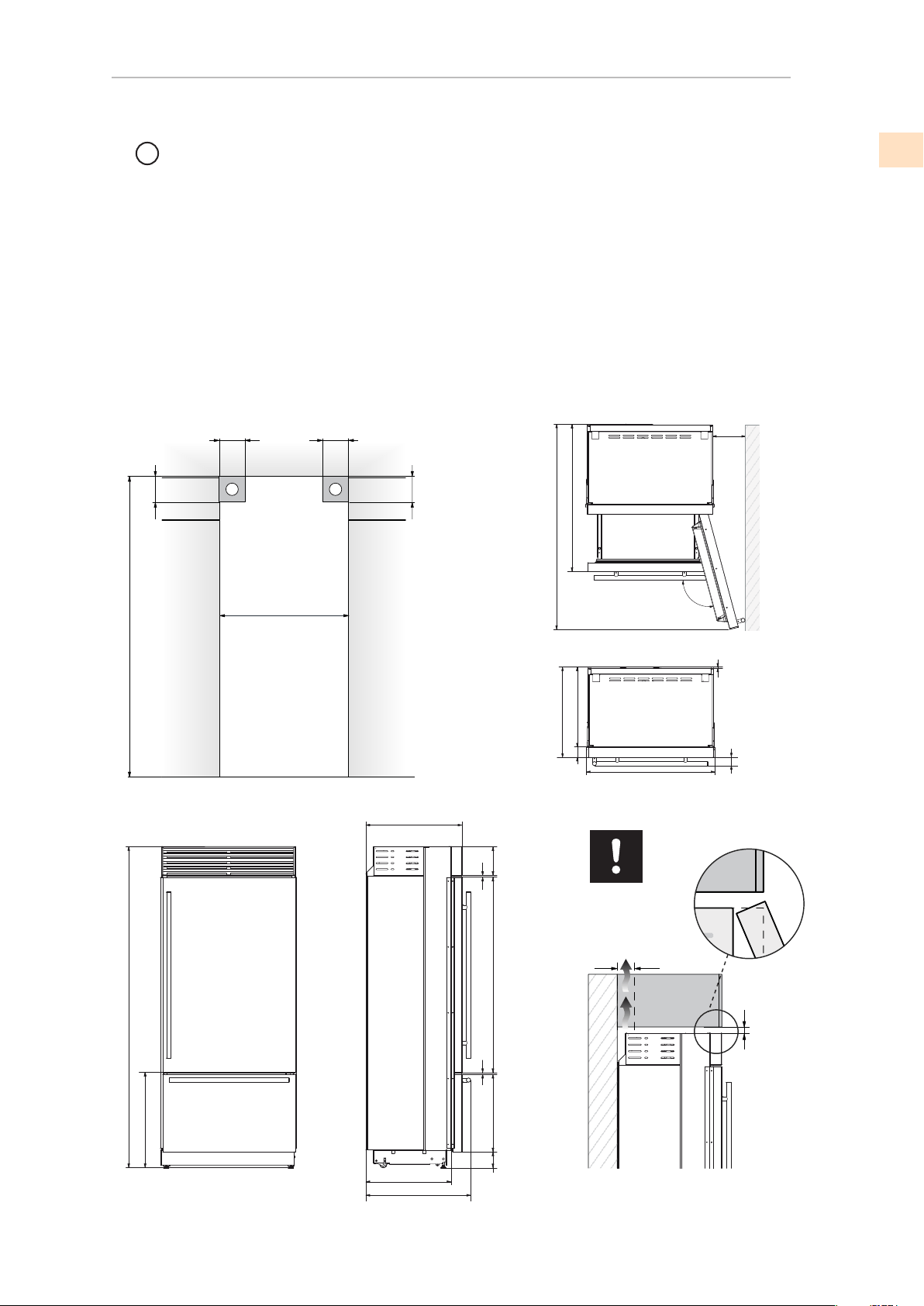
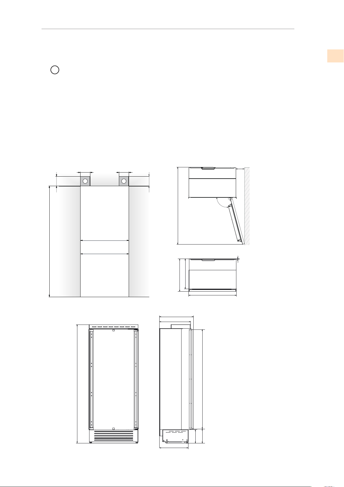
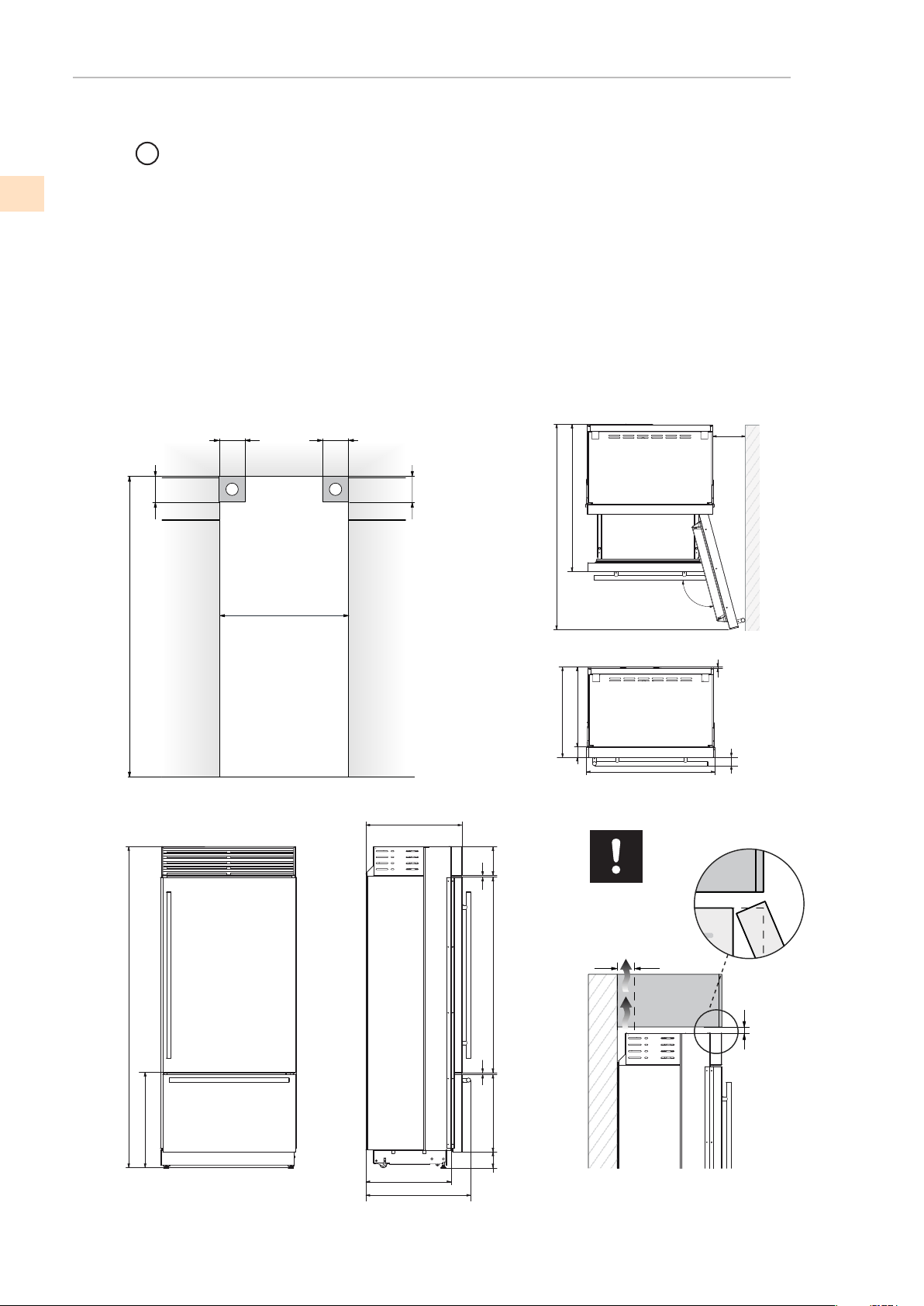
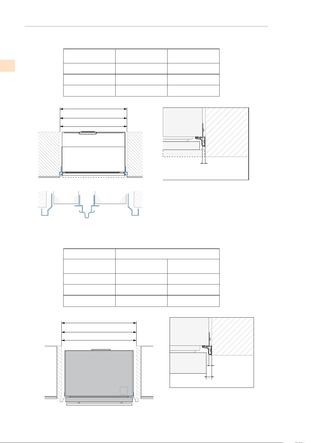
INSTALLATION CUT-OUT FEATURES - KRP MODELS
(continued)
min 10 (3⁄8”)
min 50 (2”)
2134 mm (84”)
900 mm (35 1/2”)
1470 mm (57 7/8”)
105°
899 mm (35 3/8”)
2120 mm (83 1/2”) + 25 mm (1”)
635 mm (25”)
900 (35 ½”)
A A
min 2134 (84”)
140 (5 ½”) 140 (5 ½”)
100 (4”)
100 (4”)
560 (22”)
2120 (83 ½”) +25 (1”)
613 (24 1⁄8”)+25 (1”)
635 (25”)
97 (3 7/8”)
693 (27 ¼”)
516 (20
3/8”
)
1296 (50”)
195 (7
5⁄8”)
8 (3⁄8”)
8 (3⁄8”)
1016 (40”)
1470 (57 7⁄8”
)
230 (9”)
560 (22”)
75 (3”)
899 (35 3/8”)
10 (3⁄8”)58 (2 ¼”)
105°
635 (25”)
Flush
IMPORTANT
Cut-out Height
Cut-out Width
Door Swing Clearance
Door Opening Angle
Width
Height
Depth with door
A Area to be left clear for the anti-tip brackets
LOCATION AND INSTALLATION
EN

©2018 Hestan Commercial Corporation
6
INSTALLATION CUT-OUT FEATURES - KRB MODELS
140 (5 ½”) 140 (5 ½”)
100 (4”)
100 (4”)
A A
min 2134 (84”)
900 (35
½”)
A
2134 mm (84”)
105°
2120 mm (83 1/2”) + 25 mm (1”)
610 mm (
24”)
610 (24”)
560 (22”)
1293 (50 7⁄8” )
474 (18 5⁄8” )
231 (9
1⁄8”
) +
25 (1”)
500 (19 )¾”
248 (9
¾”
)
+ 25 (1”)
20 ( )¾”
721 (28 3⁄8”) +25 (1”)
2120 (83 ½”) +25 (1”)
992 (39”)
FI36: 1470 (57 7⁄8”)
160 (6 3⁄8”)
560 (22”)
610 (24”)
899 (35 3⁄8”)
10 (3⁄8”)
105°
Area to be left clear for the anti-tip brackets
Cut-out Height
Cut-out Width
Door Swing Clearance
Door Opening Angle
Width
Height
Depth with door (without panel)
(continued)
LOCATION AND INSTALLATION
900 mm (35 1/2”)
1470 mm (57 7/8”)
899 mm (35 3/8”)
EN
©2018 Hestan Commercial Corporation
7
INSTALLATION CUT-OUT FEATURES - KRP MODELS
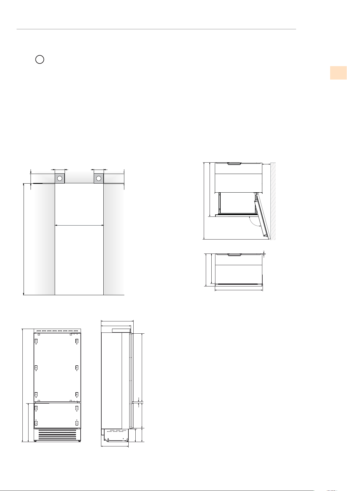
Door Opening Angle
A Area to be left clear for the anti-tip brackets
(continued)
LOCATION AND INSTALLATION
2134 mm (84”)
30”: 750 mm (29 5/8”)
24”: 600 mm (23 3/4”)
30” : 1325 mm (52 1/8”)
24” : 1175 mm (46 1/4”)
105°
30”: 749 mm (29 1/2”)
24”: 599 mm (23 5/8”)
2120 mm (83 1/2”) + 25 mm (1”)
615 mm (
24 1/4”)
Cut-out Height
Cut-out Width
Door Swing Clearance
Width
Height
Depth with door (without panel)
24” AND 30” COLUMN REFRIGERATORS AND FREEZERS
24” WINE COLUMN AND 24” REFRIGERATOR WITH WINE
140 (5 ½”) 140 (5 ½”)
100 (4”)
100 (4”)
A A
min 2134 (84”)
24”: 600 (23 ¾”)
30”: 750 (29 5⁄8”)
615 (24 1/4”)
560 (22 1/4”)
1808 (71 )¼”
231 (9
1⁄8”
) +
25 (1”)
505 (19 ¾”)
233 (9
¼”
)
+ 25 (1”)
2120 (83 ½”) +25 (1”)
30”: 1325 (52 1/8”)
24”: 1175 (46 1/4”)
30”: 53 (2 1⁄8”)
24”: 27 (1 1⁄16”)
560 (22 1/4”)
615 (24” 1/4)
30”: 761 (30”)
24”: 609 (24”)
10 (3⁄8”)
105°
EN
©2018 Hestan Commercial Corporation
8
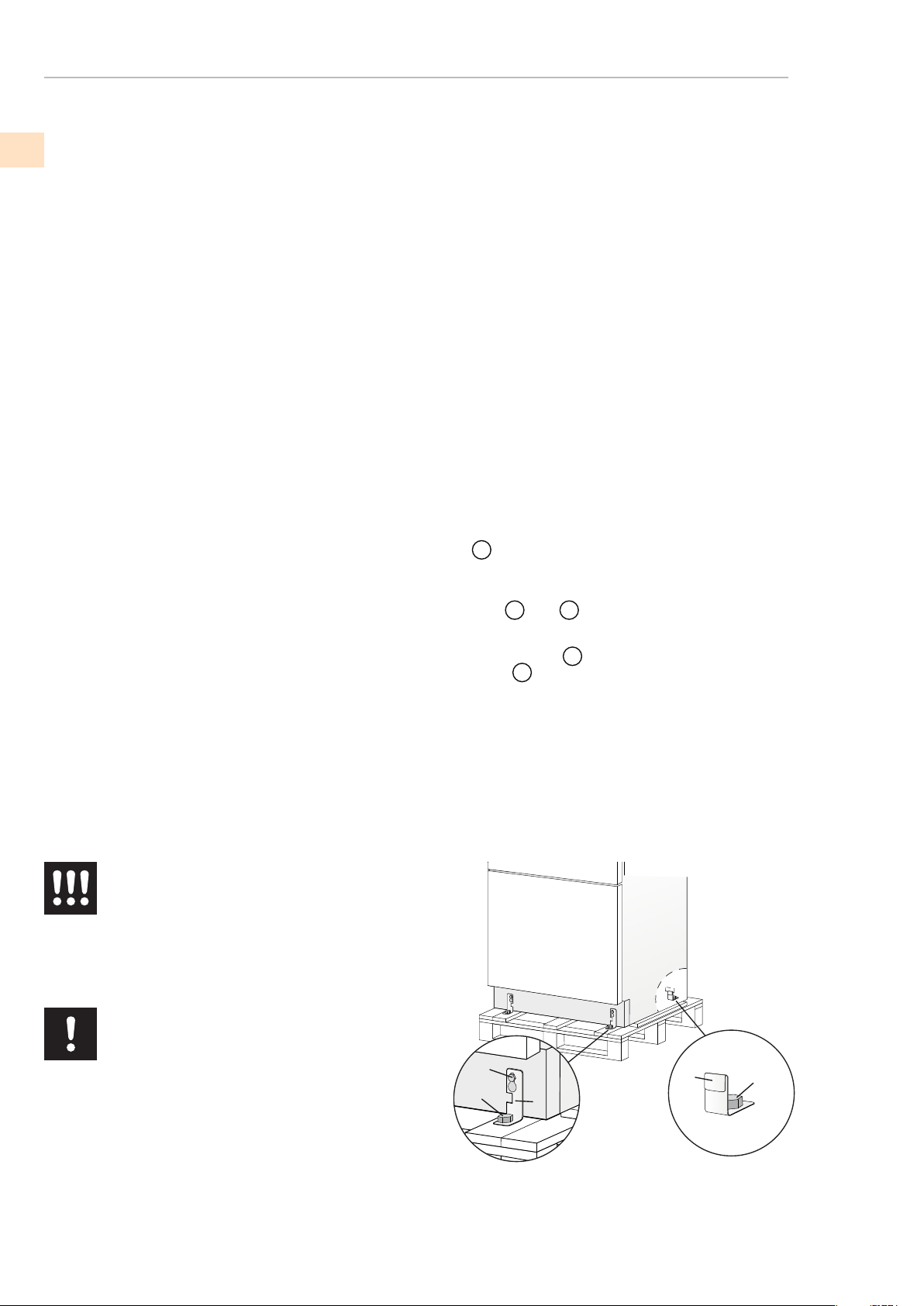
PREPARING THE INSTALLATION
(continued)
LOCATION AND INSTALLATION
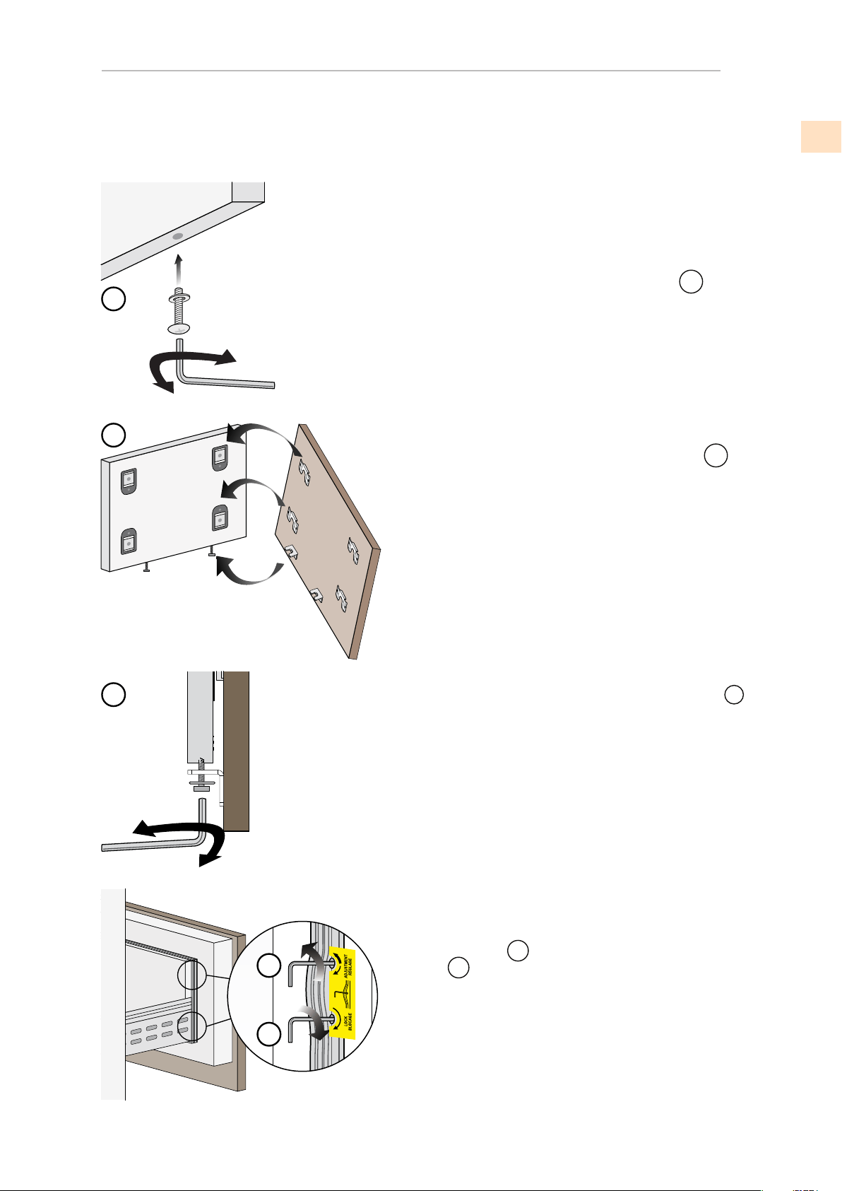
To remove the front xing bracket
Remove the xing brackets
.
truck, remove the appliance and place it on the oor.
Be very careful to avoid any damage to oors. Delicate oors should be
1
4
1
2
3
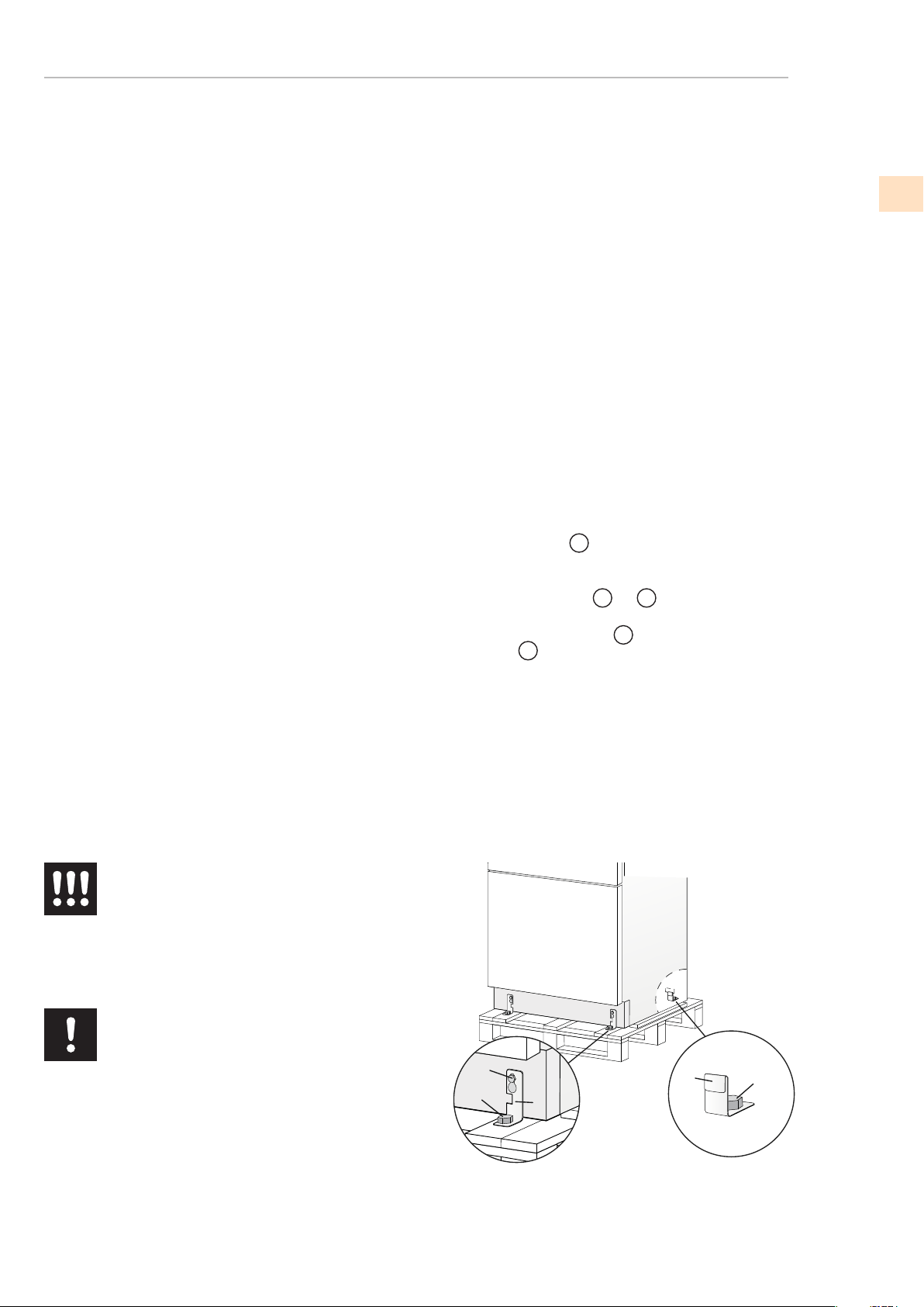
Transport to installation site
and unpacking
Since this is a large and heavy appliance, before transporting the ap-
pliance, check the access to the location where it will be installed
(door size, maneuvering space in stairwells, etc.).
The appliance is attached to the base of the packaging (pallet) through
four bolts which can be removed using a 17 mm (3/4”) wrench.
It is recommended to use a manual transporting device to move the
appliance to the installation site, and only at this point to remove the
base of the packaging.
The appliance should always be transported in a vertical position.
If this is not possible, transport the appliance laying on its rear side.
Once at the installation site, the appliance, which is equipped with four
wheels, can be taken off the pallet and positioned in the installation
area.
Operate as follows:
Take off the four bolts
1
securing the appliance to the pallet by
means of a 17 mm (3/4”) wrench.
3
and
4
3
, unscrew for one or two turns
the rear wheel adjusting bolt
2
by means of a 13 mm (1/2”) wrench.
From the back of the unit and by means of a suitable, high duty hand
protected with plywood, hard cardboard or similar material panels.
The appliance is very heavy.
Take maximum care during handling to
avoid injury.
The appliance should always be transported
in a vertical position.
Avoid at all costs leaning it on its front side.
EN

©2018 Hestan Commercial Corporation
9
CUT-OUT DIMENSIONS AND INSTALLATION METHODS - FLUSH
CUT-OUT DIMENSIONS AND INSTALLATION METHODS - NON-FLUSH
(continued)
LOCATION AND INSTALLATION
KRB36 Models
30” Columns
24” Columns and Wine
A A
B
A A
KRB36 Models
30” Columns
24” Columns and Wine
897 (35 1/4”)900 (35 1/2”)
750 (29 5/8”)
600 (23 3/4”)
747 (29 3/8”)
597 (23 1/2”)
Panel Width
Cut-out
Models
24”: 600 (23 ¾”)
30”: 750 (29 5⁄8”)
36”: 900 (35 ½”)
A Lateral/side connection kit (included accessory)
B
Central connection kit, required when joining 2 units)
900 (35 1/2”)
750 (29 5/8”)
600 (23 3/4”)
914 (36”
)
762
(30”)
610 (24”)
MAXMIN
Cut-outModels
24: 610 (24”)
30: 762 (30”)
36: 914 (36”)
A Lateral/side connection kit
A
6,5 (¼”)
A
6,5 (¼”
10 (3/8”
)
)
EN
AKRLJK
(for KRB, KRC, KFC, KWC and KRW Models)
AKRLJKP (for KRP Models)
(not included - must be ordered as a separate accessory)
AKRCJK (for KRB, KRC, KFC, KWC and KRW Models)
AKRCJKP (for KRP Models)

©2018 Hestan Commercial Corporation
10
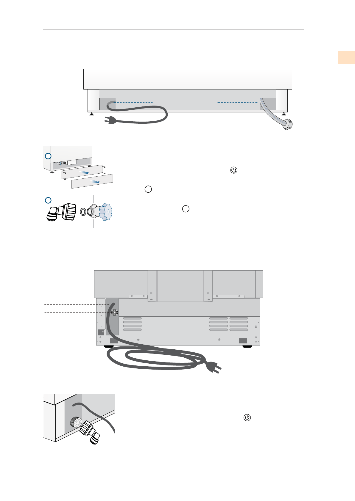
ELECTRICAL AND WATER CONNECTION
(continued)
LOCATION AND INSTALLATION
E
W
E
W
E
W
E
W
E
W
E
W
The appliances are delivered from the factory for operation at 110V-
120V AC - 60Hz (US and Canada).
They are provided with a suitable supply cable and plug to be con-
nected to an appropriate 15A socket (US and Canada) provided
with an effective grounding.
A circuit breaker should also be installed and should be easily ac-
cessible so that it can be easily switched off before performing any
installation or maintenance.
To connect to the water supply system (for appliances equipped with
ice makers) a 1/4” waterline with accessible shut-off valve must be
supplied.
The appliance is provided with a water adapter elbow which is suit-
able for high water pressure and complies the Food Regulations.
The water lter cartridge , which is provided with the appliance
should be installed according to the accompanying instructions. Use
only the new adapter which is supplied with the appliance. The so-
lenoid connection on the appliance is 3/4” diameter but is metric
threaded. A standard garden hose threaded connector such as a
braided stainless hose found at typical hardware stores will strip or
damage the solenoid threads. Use only the supplied 1/4” quick con-
nect elbow adapter for connecting a 1/4” copper or polyethylene
source water line to the appliance.
Electrical cord length: 2000 mm (78 3/4”)
Water connection line length: 2500 mm (98 3/8”)
Do not use extension cords and/or multiple adapters for the power
supply connection.
The appliance should be connected only to
a drinkable water supply system.
to drink any water which is not suitable for
human consumption.
Electrical and water supply behind the unit
Do not use extension cords or adapters.
Once the appliance is fully installed, con-
nected to the water supply (if applicable) and
operational, in the event that the water sup-
ply must be turned off,(touch the button
on
control panel to switch it off) before the main
water is shut off to prevent the appliance from
entering a ‘NO WATER IN’ alarm state.
The built-in Hestan lter cannot make it safe
KRP Models
All other Models
EN
©2018 Hestan Commercial Corporation
11
(continued)
LOCATION AND INSTALLATION
ELECTRICAL AND WATER CONNECTION
(continued)
Back of appliance
Water connection
Electrical connection
Operate as follows:
Unwind the electric cable and connect it directly to the wall socket.
Make sure the appliance is in the Stand-by condition and that all
lights are off; if not, press the Unit button
to switch it off.
Push the 1/4” source waterline fully into the elbow connector then
thread the elbow adapter to the solenoid at the back of the appli-
ance.
to make a proper seal. Turn on the water and ensure all connections
are not leaking prior to pushing the unit into the niche.
Firmly tighted with ngers - a tool or wrench should not be needed
2
1
Operate as follows:
Unwind the electric cable and connect it directly to the wall socket.
Make sure the appliance is in the Stand-by condition and that all lights
are off; if not, press the Unit button to switch it off.
Connect the water line to the threaded connection at the base of the
1
Fit the other end of the hose to the water tap, use the gaskets provided
in the Owner’s Kit.
2
make a proper seal. Turn on the water and ensure all connections are
not leaking prior to pushing the unit into the opening.
Front of appliance
Back of appliance
Water connectionElectrical connection
unit.
Firmly tighten with ngers - a tool/wrench should not be needed to
KRP MODELS
ALL OTHER MODELS
EN
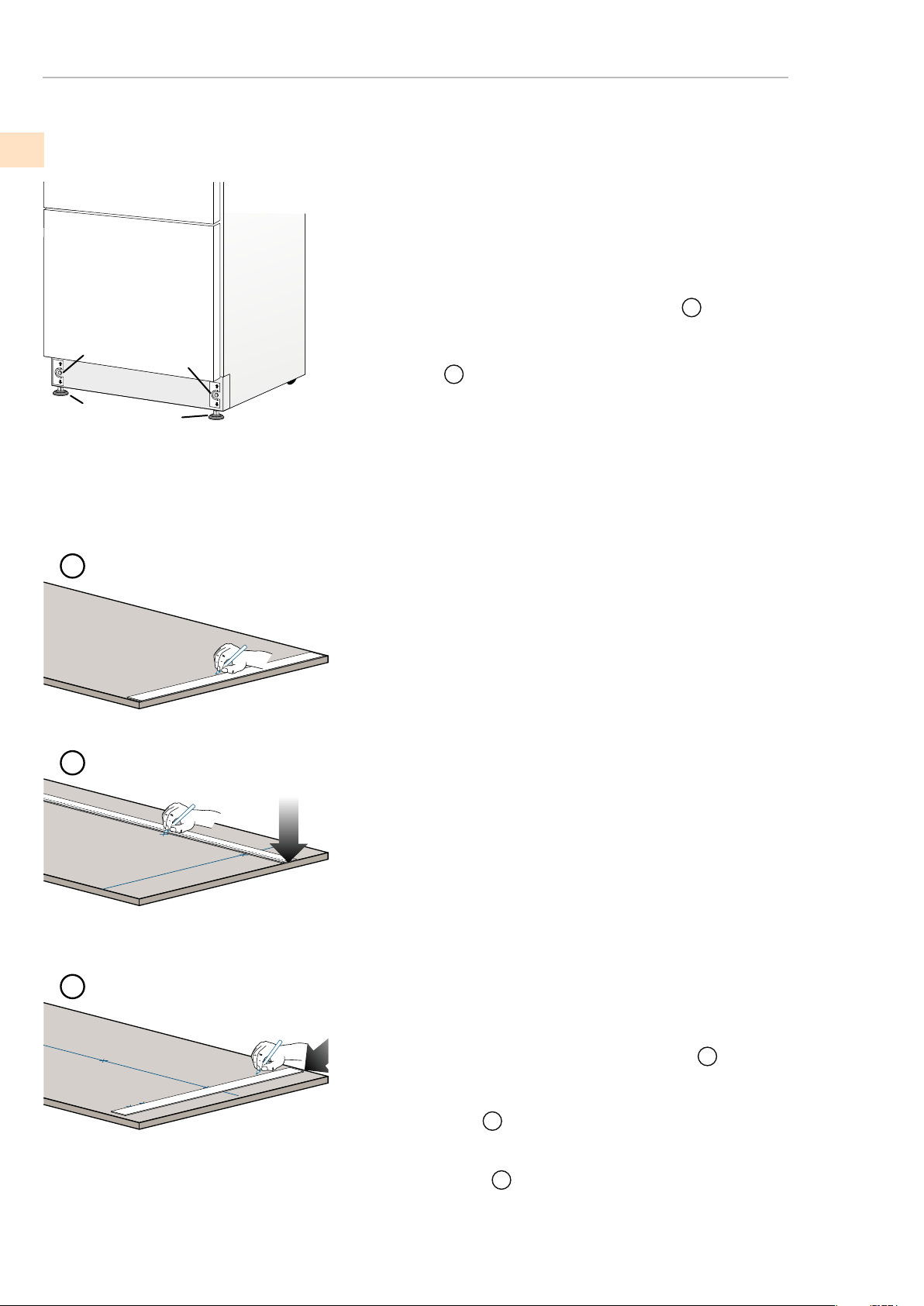
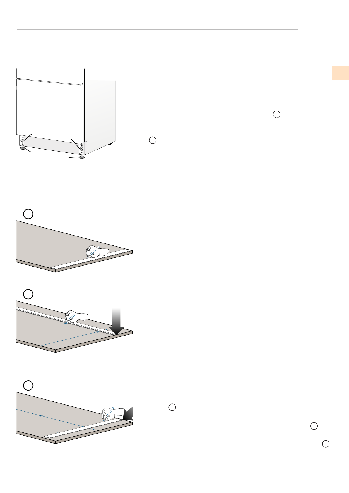
LEVELING THE REFRIGERATOR
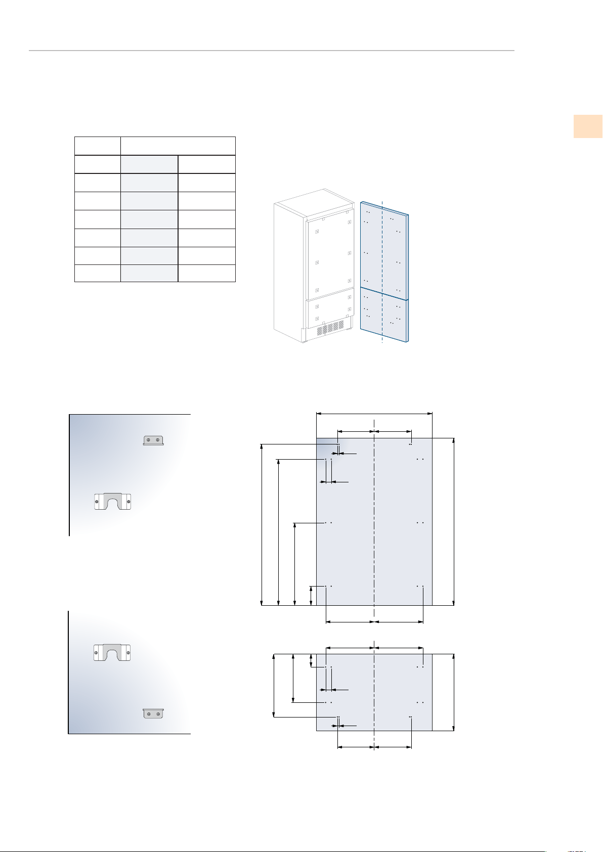
DOOR AND BOTTOM-DRAWER OVERLAY PANEL LAYOUT
(continued)
LOCATION AND INSTALLATION
1
2
1
2
Adjust the appliance level by means of the front leveling feet
and the rear adjustable wheels.
Operate as follows:
After removing the bottom plinth or grill (it is kept in position by
magnets), adjust the height of the leveling feet
1
by means of a 17
mm (3/4”) open-end or adjustable wrench.
Then adjust the height of the rear wheels by turning the front
adjusting bolts
2
clockwise or counter-clockwise as required.
Reinstall the bottom plinth or grill.
1
2
3
Decorative door and bottom-drawer panels layout:
The dimensions of the panels are indicated in the table and draw-
ings on pages 18-19.
Nevertheless, according to the requirements for aligning with other
kitchen structures, the door panel can be higher than the upper
edge of the refrigerator door, and the drawer panel can be lower
than the edge of the drawer.
The panels must be mounted using special braces which attach
to adjustable devices provided on the door and drawer and with
brackets that anchor and adjust the panel’s vertical direction.
Braces, brackets and xing screws are provided with the appliance
and must be applied to the panel as indicated.
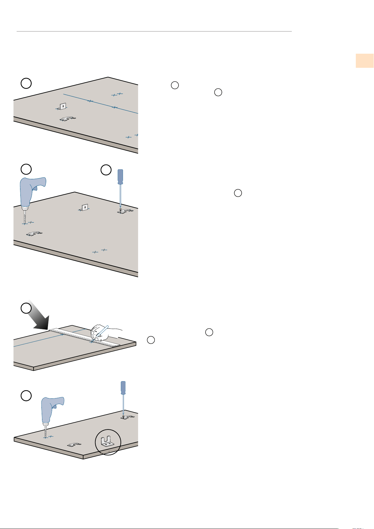
Operate as follows:
To prepare the panels to be mounted on the appliance, follow
these steps, working on the back of the panel.
Door Panel
Trace, a line dividing the panel width in half.
1
Starting from the bottom edge of the panel, mark the positioning
of the brackets.
2
Following the corresponding table, mark the external and then
the internal hole.
3
OVERLAY MODELS (-OV)
©2018 Hestan Commercial Corporation
12
EN
©2018 Hestan Commercial Corporation
13
(continued)
LOCATION AND INSTALLATION
(continued)
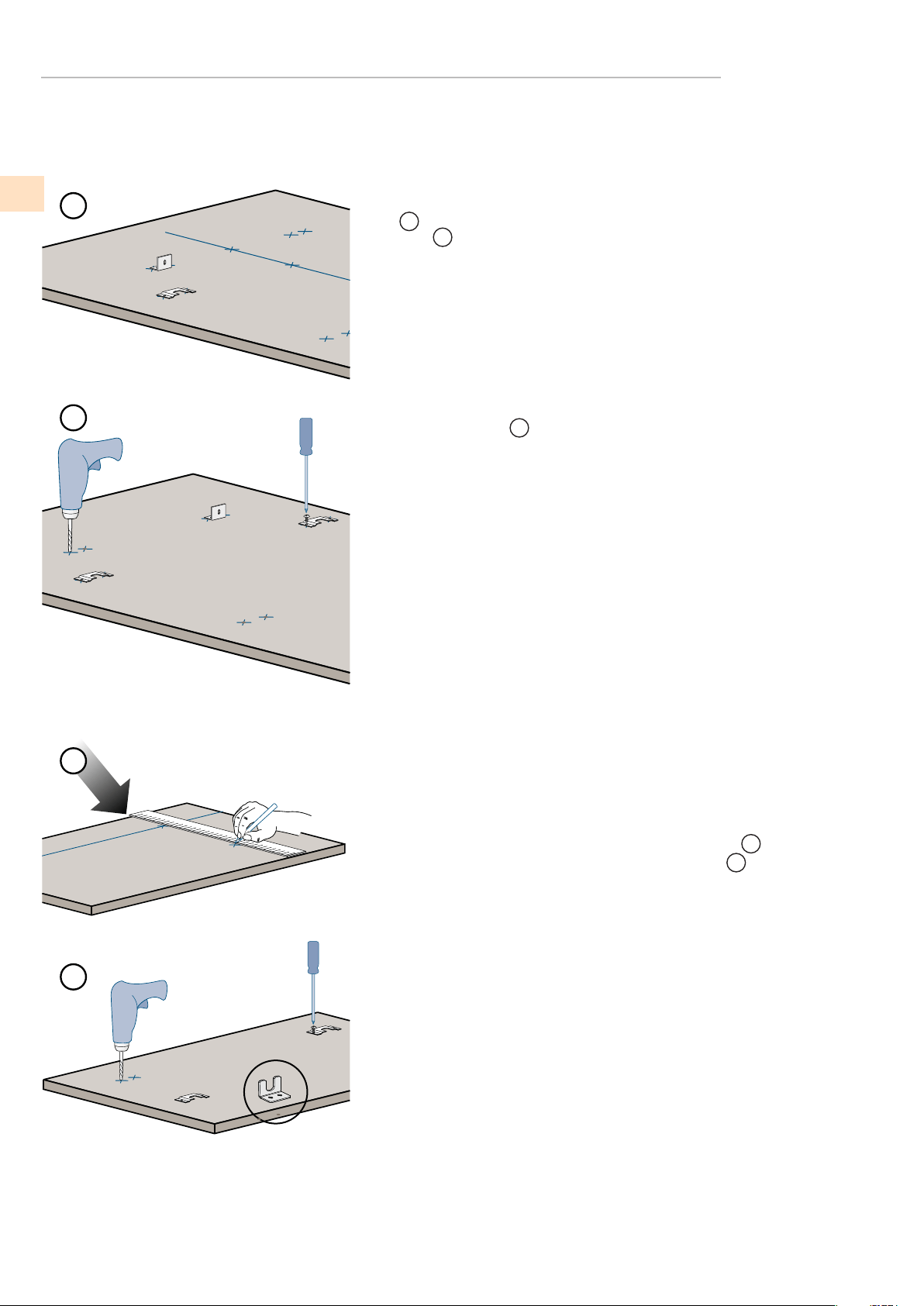
DOOR AND BOTTOM-DRAWER OVERLAY PANEL LAYOUT
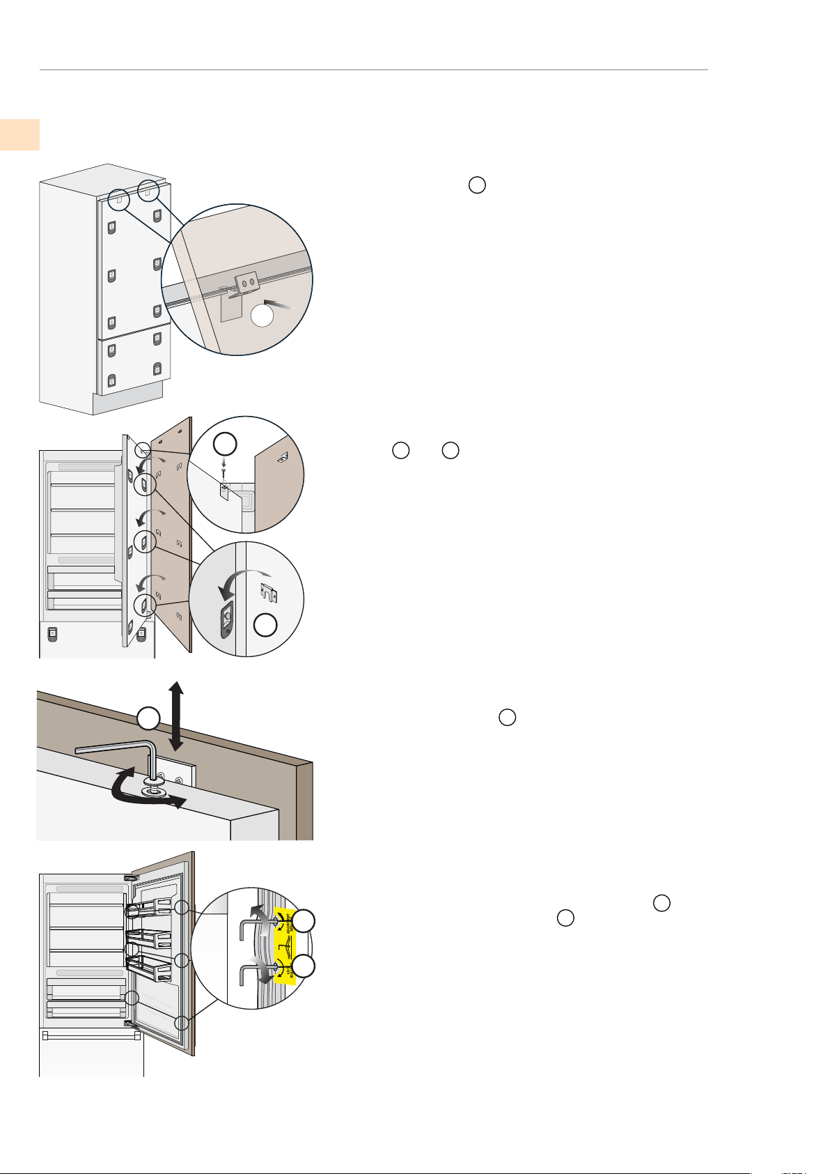
7
8
4
5
Position the brackets on each set of marks to make sure they are
aligned
4
, then drill holes through the panel (pay close attention to
the panel’s thickness)
5
Screw the brackets in place
6
Drawer Panel
When preparing the Drawer Panel, follow the same instructions as
per the door panel, but make sure measurements are taken starting
from the top edge.
7
The support bracket faces the opposite way
8
(note images 4 and 8).
OVERLAY MODELS (-OV)
EN
6
(continued)
LOCATION AND INSTALLATION
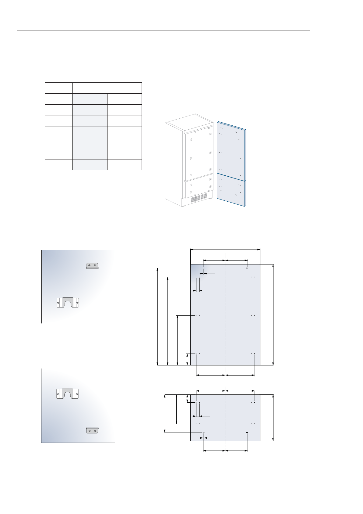
D E
D E
A
B C
F G
13 (½”)
13 (
½”)
34 (1
3/8”)
34 (1
3⁄8)”
1285 (50 5⁄8”)
1163 (45
¾”)
660 (26”)
157 (6
¼”)
min 1390 (54
¾”)max 635 (25”)
507.5 (20”)
382 (15
1⁄8”)
100 (4”)
A
897 (35 ¼”) 897 (35 ¼”)
355.5 (14”)
355.5 (14”)
261 (10 ¼”)
261 (10 ¼”)
418 (16 ½”)
418 (16 ½”)
386 (15 ¼”)
386 (15 ¼”)
B
C
D
E
354.5 (14”) 354.5 (14”)
F / G
KRB36-OV
Hinge Right
(continued)
DOOR AND BOTTOM-DRAWER OVERLAY PANEL LAYOUT
OVERLAY MODELS (-OV)
HOLE POSITIONS
Hinge Left
PANEL DIMENSIONS
©2018 Hestan Commercial Corporation
14
©2018 Hestan Commercial Corporation
15
(continued)
LOCATION AND INSTALLATION
(continued)
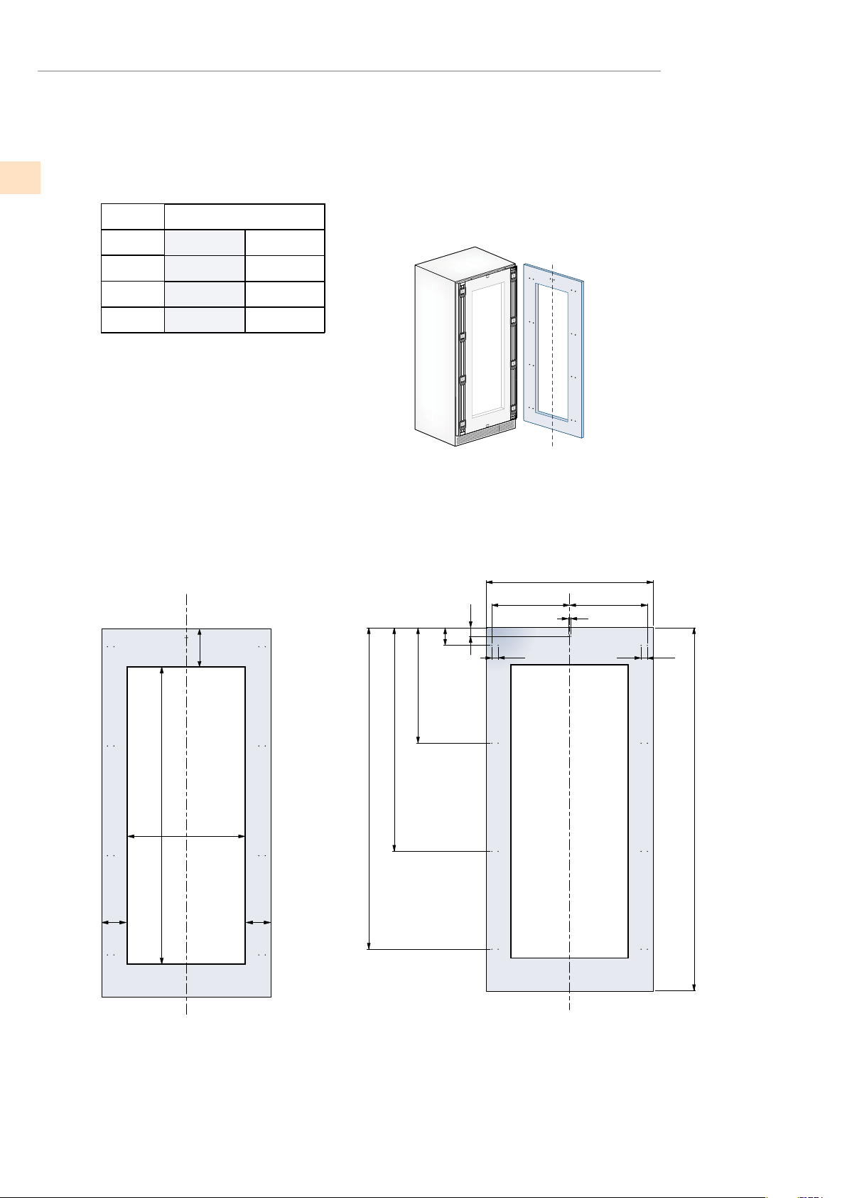
DOOR AND BOTTOM-DRAWER OVERLAY PANEL LAYOUT
OVERLAY MODELS (-OV)
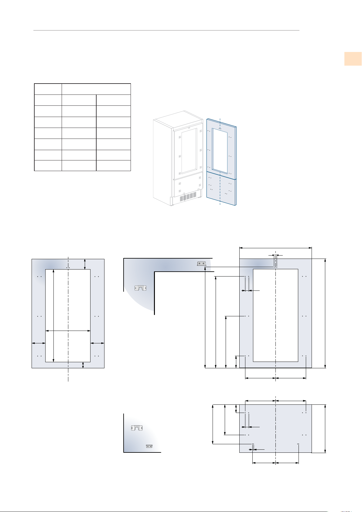
KRWR24-OV MODELS
897 (35 ¼”) 897 (35 ¼”)
354.5 (14”) 354.5 (14”)
412 (16 ¼”)
412 (16 ¼”)
380 (15”)
380 (15”)
418 (16 ½”)
418 (16 ½”)
386 (15 ¼”)
386 (15 ¼”)
A
D
E
F / G
H
I
Hinge Left
Hinge Right
H I
D E
A
F G
1286 (50 5⁄8”)
1152,5 (45 3⁄8”)
650,5 (25
5⁄8”)
148,5 (5
7⁄8”)
6,5 (¼”)
6,5 (
¼”)
13 (
½”)
34 (1
3⁄8)”
34 (1
3⁄8)”
min 1390 (54 ¾”)
max 635 (25”)
507,5 (20”)
382 (15
1⁄8”)
100 (4”)
24”: 327 (12
7⁄8” )
1075 (42 3⁄8” )
<200 (7 7⁄8”)
115 (4
½”)
135 (5 3⁄8”)
135 (5
3⁄8”)
HOLE POSITIONS
PANEL / FRAME DIMENSIONS
EN

(continued)
LOCATION AND INSTALLATION
(continued)
DOOR AND BOTTOM-DRAWER OVERLAY PANEL LAYOUT
OVERLAY MODELS (-OV)
HOLE POSITIONS
PANEL DIMENSIONS
A
747 (29 3⁄8)”
343 (13 ½”)
343 (13 ½”)
597 (23 ½”) 597 (23 ½”)
276,5 (10 7⁄8)”
276,5 (10 7⁄8)”
268 (10 ½”)
268 (10 ½”)
B
C
Hinge Left
Hinge Right
30” -OV Column Models
24”-OV Column Models
747 (29 3⁄8)”
343 (13 ½”)
343 (13 ½”)
Hinge Left
Hinge Right
1
13 (½”)
1797 (70 ¾”)
B C
A
34 (1 3⁄8” 34 (1 3⁄8)”
165 (6 ½”)
1271,5 (50”)
690,5 (27
¼”)
112 (4 3⁄8”)
min 1933 (76
1⁄8”)
©2018 Hestan Commercial Corporation
16
EN

©2018 Hestan Commercial Corporation
17
(continued)
LOCATION AND INSTALLATION
(continued)
DOOR AND BOTTOM-DRAWER OVERLAY PANEL LAYOUT
OVERLAY MODELS (-OV)
HOLE POSITIONS
FRAME DIMENSIONS
597 (23 ½”) 597 (23 ½”)
276,5 (10 7⁄8)”
276,5 (10 7⁄8)”
268 (10 ½”)
268 (10 ½”)
A
B
C
Hinge Left
Hinge Right
KWCR/L24-OV MODELS
1
13 (½”)
B C
A
34 (1 3⁄8” 34 (1 3⁄8)”
1797 (70 ¾”)
165 (6
½”)
1271,5 (50”)
690,5 (27
¼”)
112 (4
3⁄8”)
min 1933 (76
1⁄8”)
1572 (62”)
24: 327 (12 7⁄8” )
135 (5
3⁄8” )135 (5 3⁄8” )
min 200
(7
7⁄8”)
EN

(continued)
LOCATION AND INSTALLATION
(continued)
DOOR AND BOTTOM-DRAWER OVERLAY PANEL LAYOUT
OVERLAY MODELS (-OV)
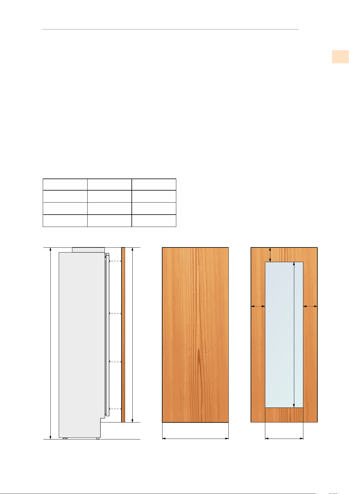
PANEL DIMENSIONS - KRBR/L36-OV AND KRWR/L24-OV MODELS
Panels can have thickness ranging between 18 mm (3/4”) and 28 mm (1-1/8“).
Door panels can have a maximum weight 23 kg (51 lbs) and drawer panels may be a maximum
weight of 11kg (25 lbs).
Exceeding these weights could void your warranty for any service issues which can be
attributed to overweight panels.
The hinge mechanism on Hestan refrigerators is considered to be `Zero-clearance`. The door
and drawer widths specied below assume the minimum niche width is being used and a 3.5mm
(1/8”) reveal is desired around the panels. Adjust your panel dimensions accordingly to your own
design criteria considering your niche width and your reveal. Minimum reveal / gap should not be
less than 1.5mm (1/16”).
KRBR/L36-OV
KRWR/L24-OV
N/A
897 (35 1/4”)
327 (12 7/8”)597 (23 1/2”)
Door/Drawer Width
A
Models
Door Cutout Width
B
2121 (83 ½") + 25 (1")
min 540 (21 ¼”)
max 635 (25”)
A B
3 (1⁄8”)
1390 (54 ¾”)
115 (4 ½”)
min 200 (7 7⁄8”)
135
(5 3⁄8”)
135
(5 3⁄8”)
1075 (42 3⁄8”)
Example:
84” cut-out height
36” cut-out width
4” toe kick height
1/8” gap desired all around
Door panel:
Width: 35-3/4”
Height: 54-3/4”
Drawer panel:
Width: 35-3/4”
Height: 84”-1/8”-54-3/4”-1/8”-4”=25”
If you want a 6” toe kick height then your bottom drawer
panel height would be 23”
©2018 Hestan Commercial Corporation
18
EN
©2018 Hestan Commercial Corporation
19
(continued)
LOCATION AND INSTALLATION
(continued)
DOOR AND BOTTOM-DRAWER OVERLAY PANEL LAYOUT
OVERLAY MODELS (-OV)
PANEL DIMENSIONS - 24” AND 30” COLUMN REFRIGERATORS AND FREEZERS
30” Columns
24” Columns
747 (29 3/8”)
597 (23 1/2”)
Models
KWCR/L24-OV
597 (23 1/2”) 327 (12 7/8”)
N/A
N/A
Door/Drawer Width
A
Door Cutout Width
B
2121 (83 ½") + 25 (1")
min 1933 (76 1⁄8”)
max 2028 (79
7⁄8”)
A B
135
(5 3⁄8”)
135
(5 3⁄8”)
min 200(7 7⁄8”)
1572 (62”)
Panels with width ranging between 18 mm (3/4 in) and 28 mm (1 1/8 in).
Door panels with weight max of 34 kg (75 lb)
Exceeding these weights could void your warranty for any service issues which can be attributed
The hinge mechanism on Hestan refrigerators is considered to be `Zero-clearance`. The door
and drawer widths specied below assume the minimum niche width is being used and a
3.5mm (1/8”) reveal is desired around the panels. Adjust your panel dimensions accordingly
to your own design criteria considering your niche width and your reveal. Minimum reveal
AND KWCR/L24-OV MODELS
to overweight panels.
or gap should not be less than 1.5mm (1/16”).
EN

(continued)
LOCATION AND INSTALLATION
(continued)
DOOR AND BOTTOM-DRAWER OVERLAY PANEL LAYOUT
OVERLAY MODELS (-OV)
MOUNTING HANDLES ON OVERLAY PANELS
Accurately measure the distance between
hole centers for correct dimensions to apply
before drilling the mounting holes in your
panels.
Handles must be mounted on the panels before the panels are applied
to the fridge.
1
Place the handle on top of the holes and insert the screws through
the panel and into the handle support.
2
(sample handle shown)
Handles not provided with Overlay (-XX) Models
©2018 Hestan Commercial Corporation
20
EN
©2018 Hestan Commercial Corporation
21
(continued)
LOCATION AND INSTALLATION
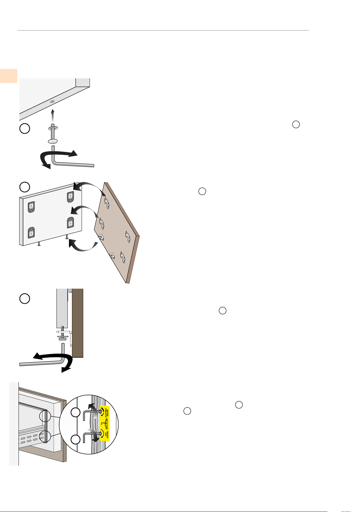
MOUNTING PANELS TO THE DOOR AND DRAWER OF
OVERLAY MODELS (-OV)
the bottom drawer.
Attach the bottom drawer panels beginning with
2
the attachment brackets at the bottom rst
3
1
2
3
4
5
Once all brackets and small brackets have been
Partially tighten the screw as illustrated.
applied to the panels, you can begin installing
1
It is now possible to align panels to adjacent cabinets
in height using the lower alignment brackets,
tightening or loosening the screws into position as
needed. With the screw slightly tightened, move the
panel sideways to align it to the other panels on the
Depth alignment: working from the inside of the drawer,
after lifting up the magnetic seal, adjust the panel
position so it is closer to or further away from the door
using the holes and then secure the panel using the
unit or other adjacent structures.
4
holes.
5
EN
(continued)
LOCATION AND INSTALLATION
(continued)
MOUNTING PANELS TO THE DOOR AND DRAWER OF
OVERLAY MODELS (-OV)
6
8
9
7
10
11
Hook the panel to the xing devices starting from the top
aligning brackets.
6
At this point, alignment between the panel and adjacent
cabinets can be adjusted using the alignment brackets and
brackets
7
and
8
Vertical alignment: tighten or loosen the screw in the brackets to
raise or lower the panel.
9
Depth alignment: working from the inside of the door, after lift-
ing up the magnetic seal, adjust the panel position so it is closer to
or further away from the door using the holes
10
and then x the
panel in position using the holes.
11
©2018 Hestan Commercial Corporation
22
EN
©2018 Hestan Commercial Corporation
23
(continued)
LOCATION AND INSTALLATION
MOVING THE UNIT INTO FINAL POSITION
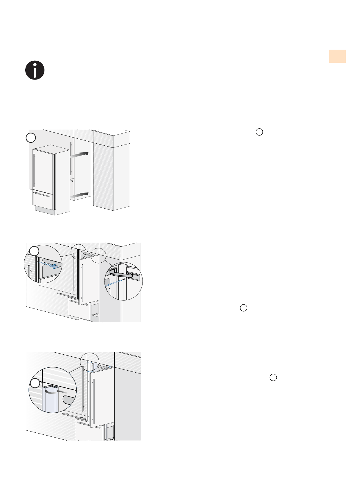
2
3
1
frames are provided.
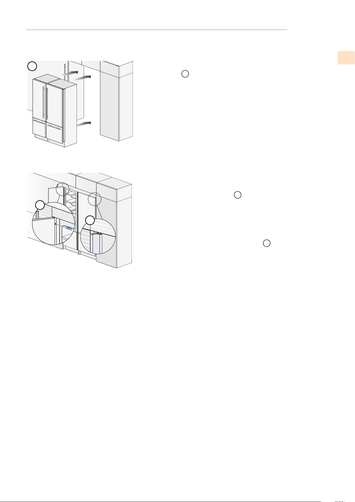
Push the appliance into the opening.
1
If the unit is to be installed inside an enclosure or within an
enclosed structure, it is necessary to design a ventilation
shaft at the back of the enclosure to assure proper
panels on the door and drawer before pushing the unit into
2
To make this operation easier keep the door and the drawer
Check the leveling of the appliance, adjusting the feet and
Mount the included covers by rst inserting them laterally
wheels to correct it if necessary.
then pushing rmly until a “click” is heard.
3
IMPORTANT: The following instructions for installation apply to all models.
For a built-in installation, to close gaps between the appliance and
ventilation at the back of the unit. A 5 mm (1/4”) gap is
sufcient to prevent overheating. Always mount front
its nal position inside the enclosure.
previously installed side proles.
open.
Secure the appliance to the adjacent cabinets using the
EN
(continued)
LOCATION AND INSTALLATION
MOVING THE UNIT INTO FINAL POSITION
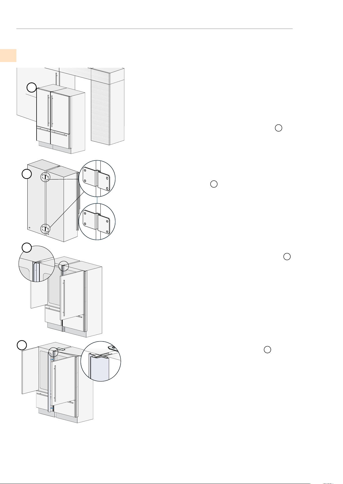
1
2
3
4
The built-in installation of two or more refrigerators requires an accessories kit, to be ordered separately:
©2018 Hestan Commercial Corporation
24
EN
AKRCJK (for KRB, KRC, KFC, KWC and KRW Models)
AKRCJKP (for KRP Models)
Special side proles are included for closing gaps between the
appliance and the adjacent cabinets.
Position the appliances in front of the installation area,
leaving enough space to operate at their back
1
On the back of the appliances, mount the joining brackets.
Attach the brackets to one of the units rst, then
subsequently to the other to complete the needed attachment
on the back of the units.
2
Place the two units side by side and join them at the front
attaching the two proles with the screws supplied.
3
Finish off by mounting the center cover frame onto the center
proles, by pushing it until a click is heard.
4
©2018 Hestan Commercial Corporation
25
5
7
6
nal position.
Once the previous steps are complete, move the unit into its
5
If the units are to be installed inside an enclosed structure,
it is necessary to design a ventilation shaft at the back of
the enclosure to assure proper ventilation at the back of the
the unit into its nal position inside the enclosure or structure.
Check the levelling of the appliance, adjusting its feet and
wheels to correct it if necessary.
6
7
unit. A 1/4” gap is sufcient to prevent overheating. Always
mount front panels on the door and drawer before moving
To make this operation easier keep the door and the drawer
previously installed side proles.
open.
Secure the appliance to the adjacent cabinets using the
Mount the included covers by rst inserting them laterally
then pushing rmly until a “click” is heard.
(continued)
LOCATION AND INSTALLATION
MOVING THE UNIT INTO FINAL POSITION
EN
(continued)
LOCATION AND INSTALLATION
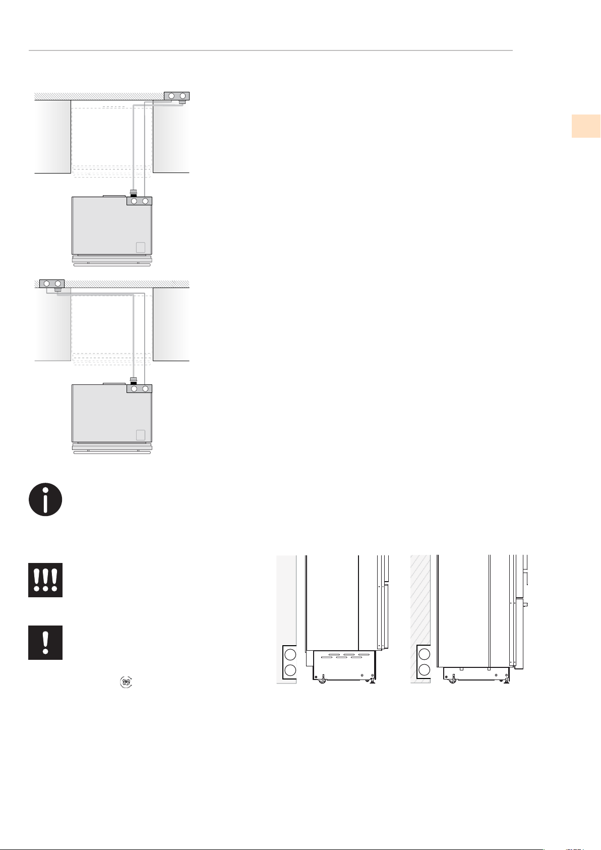
MOUNTING THE SAFETY ANTI-TIP BRACKET
The built-in installation of two or more refrigerators requires an accessories kit, to be ordered separately:
152 (6”)
59 (
2
3⁄8
”)
45 (1
5⁄8
”)
1
2
3
4
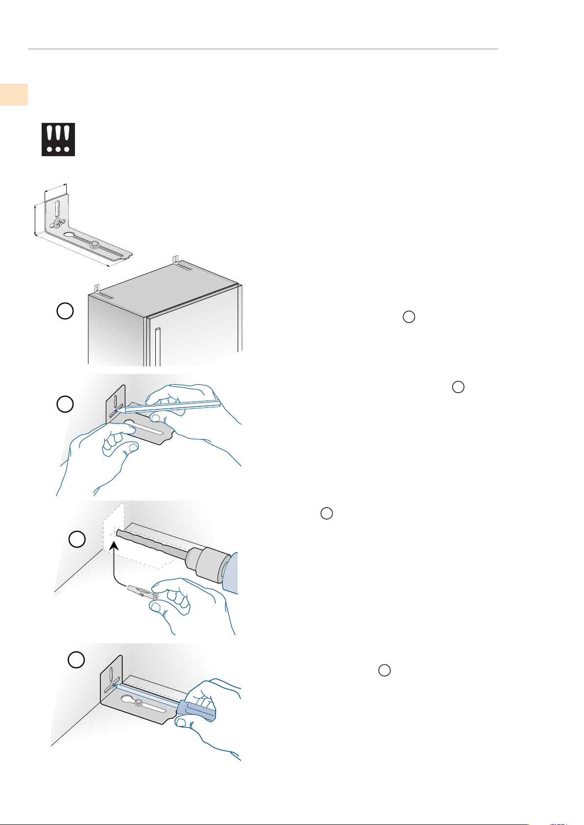
To avoid danger of the appliance tipping over
it is mandatory to secure the appliance to the
wall by means of two special brackets.
To prevent the appliance from tipping over, an extra-long kit
is available upon request if the appliance needs to remain
distanced from the wall, it is mandatory to install two
The brackets should be applied as illustrated using the
provided screws and wall anchors.
Place a bracket on the top of the appliance aligning it with
1
Mark up the holes position on the wall
2
Drill the wall with an 8 mm (3/8”) bit and insert the
Reposition the bracket and securely attach it rst to the
3
4
brackets on the upper part of the wall.
the secure location on the wall.
wall anchor.
cabinet, then to the wall.
©2018 Hestan Commercial Corporation
26
EN

©2018 Hestan Commercial Corporation
27
MOUNTING THE SAFETY ANTI-TIP BRACKET
1
2
3
To avoid danger of the appliance tipping over
it is mandatory to secure the appliance to the
wall by means of two special brackets.
To avoid danger of the appliance tipping over when
opening full doors and drawers, it is mandatory to
The brackets should be applied as illustrated using the
provided screws and wall anchors.
Place the bracket on the top of the appliance relative
1
Mark up the holes position on the wall.
2
Drill the wall with an 8 mm (3/8”) bit and insert the
3
then to the wall.
for securing it to the wall.
install two brackets on the upper part of the appliance
to the proper alignment to the wall.
wall anchor.
Reposition the bracket and secure it rst to the cabinet,
(continued)
LOCATION AND INSTALLATION
EN
(continued)
LOCATION AND INSTALLATION
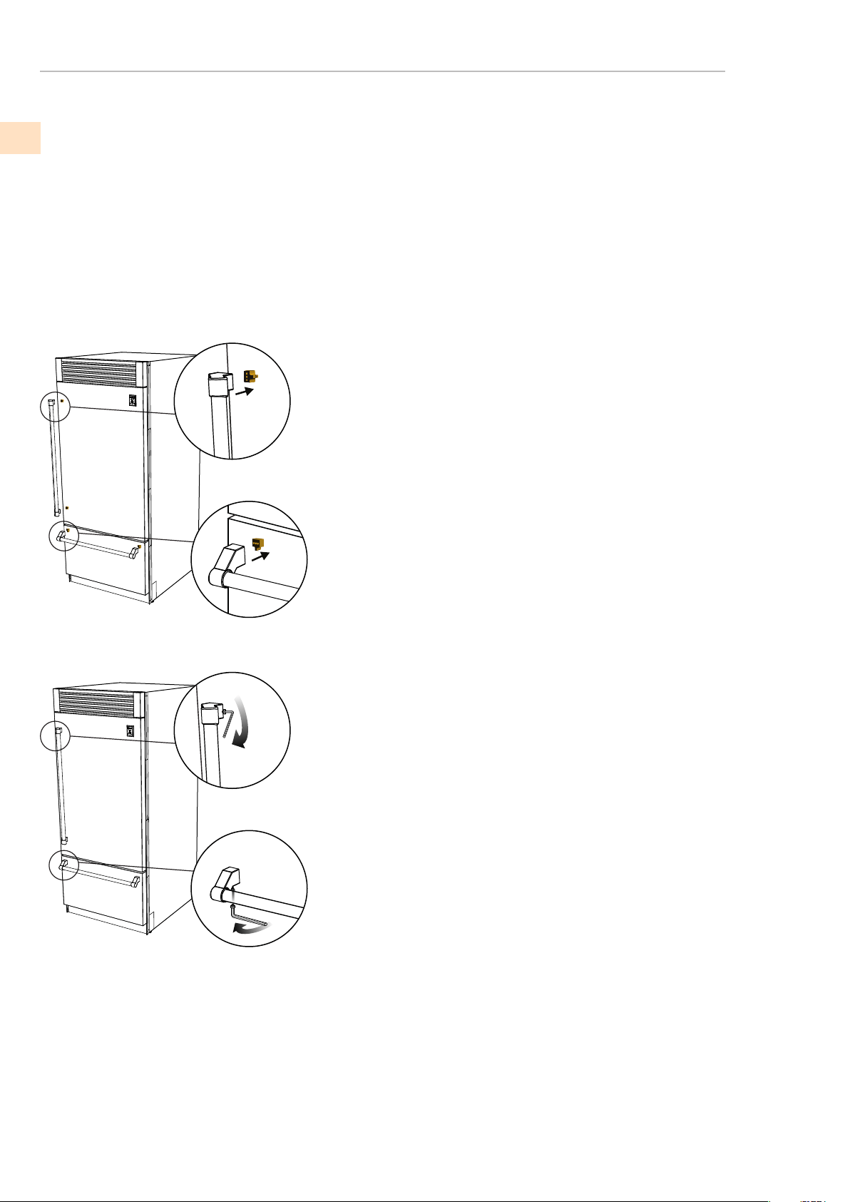
MOUNTING THE HANDLES AND ENDCAPS
Handles and endcaps are provided with all stainless and color models. Handles are located
in protective wrapping, taped to the back of the refrigerator. Remove the handles before
moving the refrigerator into its cut-out or opening. Endcaps are located in a cardboard box
inside the refrigerator.
It is recommended that two people work together to assemble and apply the handles and
endcaps. Follow the steps below to complete the mounting process.
Insert the handle into the endcaps and position the endcaps over
the supports that are pre-mounted on the door and drawer. Use
caution not to scratch the door surface. It is recommended that
one person holds the handle and endcaps in position while the
second person inserts the provided set screws used to secure the
handle.
The provided set screws are located in the box with the endcaps
Using a 1/8” (2.5 mm) hex wrench, insert the set screw into the
hole in the endcap and carefully tighten. The endcap is then
properly secured to the door/drawer. Repeat this step for the other
endcaps.
©2018 Hestan Commercial Corporation
28
EN

©2018 Hestan Commercial Corporation
29
REQUIRED VENTILATION
PROPER AIR CIRCULATION
(Decorative grill covers apply to all models except KRP top compressor models)
A forced air system assures ventilation through a grill positioned
in the lower front or upper part of the unit. If the kitchen design
includes an applied toekick, it must have ample openings/slots to
any size and shape, provided that the total open area amounts to 50% of
the overall size of the decorative cover.
the front grille included with the unit. The grille is secured to the unit
with magnetic plates and can be easily removed. The cover should be
removed for regular cleaning and removal of dust. If a decorative
grill is used, remove the provided grill to allow for proper air ow.
maintain proper air ow as illustrated below. Holes/slots can be of
In this case, to guarantee proper air ow, it is recommended to remove
860 (33 7/8”)
740 (29 1/8”)
560 (22”)
>100 (4”)
10 (3/8”)
30” Models
24” Models
100 (4”)
The chart and illustration below provides the proper amount of
air ow necessary to maintain (not available for KRP models).
A
B
C
C
A
B
C
36” Models
EN

(continued)
REQUIRED VENTILATION
TESTING AND INITIAL START UP
Ventilation is provided by a forced air system through a grill in the top of the refrigerator.
This open space in the grill cannot be restricted by any cover or device that would reduce
the proper air ow, product efciency and energy consumption.
PROPER AIR CIRCULATION (KRP top compressor models)
PRETEST CHECKLIST
Check that the front levelling feet have been properly installed.
Check that the connection to the water system does not have any
leaks and that the closing tap is easily accessible.
Check that the electrical connection is correctly installed and that
the circuit breaker and socket are easily accessible.
Check the perfect alignment of the appliance with adjacent
structures.
Check that all adhesive tape and external or internal temporary
protective packaging have been removed.
Check the perfect closing of the doors and the smooth sliding of
the drawers and shelves.
©2018 Hestan Commercial Corporation
30
EN

©2018 Hestan Commercial Corporation
31
TESTING AND INITIAL START UP
INITIAL START UP
(continued)
Having already plugged in the refrigerator, the initial indicator that
it is powered up is to see “Stand by” in the display.
To turn on all the appliance by pressing the Power button for three
seconds. The display will show the message “Initial test” for approximately
2 minutes. After this phase the compressors will start up and remain on until the
preset default temperature set at the factory is reached. Allow ample time for
the refrigerator to reach this temperature before loading any items (up to 6-12 hrs).
make sure that the water filter is properly installed. The ice maker system
will begin operation once the appliance is turned on and will begin an
Ice Maker on again by touching the button.
For further information about the appliance operation, refer to the Use and Care Manual.
If the refrigerator is provided with an ice maker, prior to turning it on
initial cleaning procedure. Once the procedure has completed, turn the
If at rst the Start Up message does not appear but other information
in the display do appear (such as Fridge too warm, Freezer too warm, or
sound signals are activated), the refrigerator has still begun the
normal cooling process.
If this is the case, deactivate any audible signals by pressing the Alarm button,
close the door and wait until the set temperature is reached.
It is necessary to let the unit reach the correct temperature prior to
food or beverages (up to 6-12 hours).
EN

DANGER. Ce symbole indique des informations et avertissements
qui doivent impérativement être respectés pour ne pas compromettre
la sécurité des personnes ou endommager l’appareil.
DANGER ÉLECTRIQUE.C e symbole indique des informations
et avertissements concernant les circuits électriques qui doivent
impérativement être respectés pour ne pas compromettre la sécurité
des personnes ou endommager l’appareil.
Ce symbole indique des informations et avertissements de caractère
général.
DÉFINITIONS DE SÉCURITÉ
LISEZ ATTENTIVEMENT ET COMPLÈTEMENT CES INSTRUCTIONS AVANT
D’INSTALLER OU D’UTILISER VOTRE APPAREIL AFIN DE RÉDUIRE LES
RISQUES D’INCENDIE, DE BRÛLURE OU D’AUTRES BLESSURES. CONSERVER
CE MANUEL POUR RÉFÉRENCE FUTURE.
INSTALLATEUR: LAISSER CE MANUEL AVEC LE PROPRIÉTAIRE DE L’APPAREIL.
PROPRIÉTAIRE: CONSERVEZ CE MANUEL POUR RÉFÉRENCE FUTURE.
Ne pas entreposer ou utiliser d’essence ou tout autre liquide ou gaz inflammable à proximité
de cet appareil ou de tout autre appareil.
EN PRÉSENCE D’UNE ODEUR DE GAZ:
1. Ne tenter d’allumer aucun appareil.
2. Ne toucher à aucun commutateur électrique.
3. N’utiliser aucun téléphone dans l’immeuble.
4. Appeler immédiatement le fournisseur de gazà partir d’un téléphone situé à l’extérieur
del’immeuble ; Suivre les instructions dufournisseur de gaz.
S’il est impossible de joindre le fournisseur degaz, appeler le service des incendies.
L ’installation et la réparation doivent être effectuées par un installateur ou une agence
deréparation ayant les qualifications requises oupar le fournisseur de gaz.
LE NON-RESPECT À LA LETTRE DE CES INSTRUCTIONS PEUT CAUSER
UN INCENDIE OU UNE EXPLOSION, QUI POURRAIT ENTRAÎNER DES
DOMMAGES MATÉRIELS, DES BLESSURES OU LA MORT.
FR
©2018 Hestan Commercial Corporation

FR
©2018 Hestan Commercial Corporation
1
EMPLACEMENT ET INSTALLATION
MISE À LA TERRE ÉLECTRIQUE
• Cet appareil doit être mis à la terre. La mise à la terre réduit le risque de choc électrique dans le
événement d'un court-circuit. Lisez la section CONNEXIONS ÉLECTRIQUES de ce manuel
pour des instructions complètes.
• NE PAS broyer sur un tuyau de gaz.
• N'UTILISEZ PAS de rallonge avec cet appareil.
• N'AYEZ PAS de fusible dans le circuit NEUTRE ou TERRE. Un fusible au NEUTRE
ou le circuit de MISE À LA TERRE pourrait entraîner un choc électrique.
S’il est bien entretenu, cet appariel Hestan procurera un service sûr et fiable pendant de nombreuses
années. Lorsqu’on se sert de cet appareil, les pratiques élémentaires suivantes en matière de sécurité
doivent être adoptées.
Conservez ces instructions pour l’utilisation locale de l’Inspecteur du gaz ou des services publics.
Cette cuisinière N’EST PAS conçue pour être installée dans des maisons préfabriquées (mobiles) ou dans
des véhicules récréatifs. N’installez PAS cette cuisinière à l’extérieur.
PRÉCAUTIONS DE SÉCURITÉ - AVANT DE COMMENCER
RISQUE DE CHOC ÉLECTRIQUE
Débranchez l’alimentation avant d’installer ou d’entretenir l’appareil. Avant de le
mettre sous tension, assurez-vous que toutes les commandes sont en position «OFF».
Ne pas le faire peut entraîner la mort ou un choc électrique.
PRÉCAUTIONS DE SÉCURITÉ - AVANT DE COMMENCER
NUMÉROS DE MODÈLE
ÉTIQUETTE DE NOTATION
EXIGENCES RÉGLEMENTAIRES / CODE
TABLE DES MATIÈRES
1
2
3
3
4
4
29
30
POUR LA SÉCURITÉ DES ENFANTS
VENTILATION REQUISE
MISE EN MARCHE

©2018 Hestan Commercial Corporation
2
MODÈLES DE RÉFRIGÉRATION
MODÈLES DE CONGÉLATEUR
Modèle No.
La description
KRPR36 Réfrigérateur à congélateur inférieur, compresseur supérieur, pro, charnière droite, 36"
KRPL36 Réfrigérateur à congélateur en bas, compresseur supérieur, Pro, articulé à gauche, 36"
KRPR36-XX Réfrigérateur à congélateur inférieur, compresseur supérieur, Pro, couleur, charnière droite, 36"
KRPL36-XX Réfrigérateur à congélateur inférieur, compresseur supérieur, Pro, couleur, articulé à gauche, 36"
KRBR36 Réfrigérateur à congélateur inférieur, compresseur inférieur, à charnière droite, 36"
KRBL36 Réfrigérateur à xation par le bas, compresseur inférieur, articulé à gauche, 36"
KRBR36-OV Réfrigérateur inférieur, compresseur inférieur, recouvrement, charnière droite, 36”
KRBL36-OV Réfrigérateur inférieur, compresseur inférieur, recouvrement, charnière gauche, 36”
KRBR36-XX Réfrigérateur à congélateur en bas, compresseur inférieur, couleur, articulé à droite, 36"
KRBL36-XX Réfrigérateur inférieur, compresseur inférieur, couleur, charnière gauche, 36"
KRCR24 Colonne de réfrigérateur, articulé à droite, 24"
KRCL24 Colonne de réfrigérateur, charnière gauche, 24"
KRCR24-OV Colonne de réfrigérateur, recouvrement, charnière droite, 24"
KRCL24-OV Colonne de réfrigérateur, recouvrement, charnière gauche, 24"
KRCR24-XX Colonne de réfrigérateur, couleur, charnière droite, 24"
KRCL24-XX Colonne de réfrigérateur, couleur, charnière gauche, 24"
KRCR30 Colonne de réfrigérateur, articulée à droite, 30"
KRCL30 Colonne de réfrigérateur, articulé à gauche, 30"
KRCR30-OV Colonne de réfrigérateur, recouvrement, charnière droite, 30"
KRCL30-OV Colonne de réfrigérateur, recouvrement, articulé à gauche, 30"
KRCR30-XX Colonne de réfrigérateur, couleur, articulé à droite, 30"
KRCL30-XX Colonne de réfrigérateur, couleur, articulé à gauche, 30"
KFCR24 Colonne de congélateur, à charnière droite, 24"
KFCL24 Colonne de congélateur, articulé à gauche, 24"
KFCR24-OV Colonne de congélateur, recouvrement, charnière droite, 24”
KFCL24-OV Colonne de congélateur, recouvrement, charnière gauche, 24"
KFCR24-XX Colonne de congélateur, couleur, charnière droite, 24"
KFCL24-XX Colonne de congélateur, Couleur, articulé à gauche, 24"
KFCR30 Colonne de congélateur, à charnière droite, 30"
KFCL30 Colonne de congélateur, articulé à gauche, 30"
KFCR30-OV Colonne de congélateur, recouvrement, charnière droite, 30”
KFCL30-OV Colonne de congélateur, recouvrement, articulé à gauche, 30”
KFCR30-XX Colonne de congélateur, couleur, à charnière droite, 30"
KFCL30-XX Colonne de congélateur, couleur, articulé à gauche, 30"
NUMÉROS DE MODÈLE
Modèle No.
La description
FR
L'étiquette de classement se trouve sur le mur intérieur du réfrigérateur.
MODÈLES DE VIN
(a continué)
KWCR24 Colonne de vin, charnière droite, 24"
KWCL24 Colonne de vin, articulé à gauche, 24"
KWCR24-OV Colonne de vin, recouvrement, charnière droite, 24"
KWCL24-OV Colonne de vin, recouvrement, charnière gauche, 24"
KWCR24-XX Colonne de vin, couleur, charnière droite, 24"
KWCL24-XX Colonne de vin, couleur, articulé à gauche, 24"
KRWR24 Réfrigérateur avec vin, charnière droite, 24"
KRWL24 Réfrigérateur avec vin, articulé à gauche, 24"
KRWR24-OV Réfrigérateur avec vin, recouvrement, charnière droite, 24"
KRWL24-OV Réfrigérateur avec vin, recouvrement, charnière gauche, 24"
KRWR24-XX Réfrigérateur avec vin, couleur, charnière droite, 24"
KRWL24-XX Réfrigérateur avec vin, couleur, articulé à gauche, 24"
ozFridge Gas Fill Charge
Quantité de Gaz Réfrigerateur
Freezer Gas Fill Charge
Quantité de Gaz Congélateur
Total Absorbed Current
Courant Absorbée Totale
Voltage
Tension
Frequency
Frequence
Refrigerant Gas Type
Type de Gaz Rèfrigerant
MODEL
Made in Italy
CODE
SER.NO./N° SERIE
3186660
ETL LISTED
CONFORMS TO
ANSI/UL STD 250
CERTIFIED TO CAN/CSA
STD C22.2 NO.63
A
V
Hz
HESTAN COMMERCIAL CORP.
ANAHEIM, CA - USA
KRP36
7
0
1
115
60
R134a
FI24RC-RO
F20160725000001
NUMÉROS DE MODÈLE
Modèle No.
La description
NOTE: -XX indique le modèle de couleur.
-BK for Stealth - Noir
-YW for Sol - Jaune
-PP for Lush - Violet
-GG for Pacific Fog - Gris graphite
-WH for Froth - Blanc
-OR for Citra - Orange
-BU for Prince - Bleu
-RD for Matador - Rouge
-BG for Tin Roof - Bourgogne
-GR for Grove - Vert
-TQ for Bora Bora - Turquoise
ÉTIQUETTE DE NOTATION
sur votre Hestan appareil tel que le modèle et le numéro de série
et tarif Electrique.
L'étiquette de notation contient des informations importantes
EXIGENCES RÉGLEMENTAIRES / CODE
L'installation de cet appareil de réfrigération doit être faite conformément aux codes locaux.
En l'absence de codes locaux, cette unité doit être installée conformément à la norme code
et codes locaux.
Cet appareil doit être mis à la terre conformément aux codes locaux ou, en l'absence de
des codes locaux avec le National Electrical Code
ANSI/NFPA 70
, ou Canadian Electrical code
CSA C22.1
.
ÉTIQUETTE DE NOTATION TYPIQUE
FR

©2018 Hestan Commercial Corporation
4
w: 650 mm (25 5/8”) h: 2260 mm (89”) d: 800 mm (31 1/2”)
w: 800 mm (31 1/2”) h: 2260 mm (89”) d: 800 mm (31 1/2”)
230 kg (507 lb)
30” Modèles
36” Modèles
275 kg (606 lb)
w: 950 mm (37 3/8”) h: 2260 mm (89”) d: 800 mm (31 1/2”)
295 kg (650 lb)
DIMENSIONS ET POIDS EMBALLÉS
ÉLECTRICITÉ ET APPROVISIONNEMENT EN EAU
ACCESSOIRES D'INSTALLATION FOURNIS
OUTILS NÉCESSAIRES
24” Modèles
Les outils suivants sont nécessaires pour l'installation du réfrigérateur:
•
•
•
•
Les pages suivantes fournissent les informations nécessaires pour une installation correcte du
réfrigérateur et sont disposés comme suit:
INSTRUCTIONS POUR L'INSTALLATION
110V 60Hz 15a
From 0.05 MPa to 0.5 MPa (0.5 Bar - 5 Bar)
3/4” female attachment
Kit de montage sur panneaux personnalisé (inclus avec les modèles -OV uniquement)
Kit anti-renversement
Kit de raccordement latérale
Cl a six pans de 4 mm (1/8”) é
Tension d’alimentation
Pression d'alimentation de l’eau potable:
Tuyau d’alimentation de l’eau:
POUR LA SÉCURITÉ DES ENFANTS
DANGER : Risque d’enfermement pour les enfants. Avant de jeter un
vieux réfrigérateur ou congélateur :
• Retirer les portes
• Laisser les étagères en place afin d’empêcher que des enfants grim-
pent dedans.
EMPLACEMENT ET INSTALLATION
PRÉPARATION
Avant de déplacer le lave-vaisselle, protégez tout revêtement de sol fini et fermez la porte
pour éviter les dommages. NE PAS soulever le lave-vaisselle par la poignée de la porte.
Assurez-vous que l'alimentation peut être fournie à l'emplacement sélectionné.
•
Données techniques.
• Dimensions de découpe de l'installation, dégagements requis et instructions de montage.
• Exigences électriques et connexions.
• Inspection et test de fuite.
Tournevis cruciforme
Perceuse à bois et à percussion
Pointe pour bois de 2.5 mm (1/8”)
Pointe pour mur de 8 mm (3/8”)
Clé ouverte de 17 mm (3/4”)
•
FR
CARACTÉRISTIQUES D'INSTALLATION - MODÈLES KRP
min 10 (3⁄8”)
min 50 (2”)
2134 mm (84”)
900 mm (35 1/2”)
1470 mm (57 7/8”)
105°
899 mm (35 3/8”)
2120 mm (83 1/2”) + 25 mm (1”)
635 mm (25”)
900 (35 ½”)
A A
min 2134 (84”)
140 (5 ½”) 140 (5 ½”)
100 (4”)
100 (4”)
2120 (83 ½”) +25 (1”)
613 (24 1⁄8”)+25 (1”)
1016 (40”)
1470 (57 7⁄8”
)
230 (9”)
560 (22”)
75 (3”)
899 (35 3/8”)
10 (3⁄8”)58 (2 ¼”)
105°
635 (25”)
Flush
IMPORTANT
A
(a continué)
EMPLACEMENT ET INSTALLATION
Espace à réserver aux équerres anti-renversement
Largeur de l’encastrement
Encombrement avec porte ouverte
Angle d’ouverture de la porte
Largeur
Profondeur (sans panneau)
Hauteur de l’encastrement
Hauteur
560 (22”)
635 (25”)
97 (3 7/8”)
693 (27 ¼”)
516 (20
3/8”
)
1296 (50”)
195 (7
5⁄8”)
8 (3⁄8”)
8 (3⁄8”)
FR
©2018 Hestan Commercial Corporation
6
140 (5 ½”) 140 (5 ½”)
100 (4”)
100 (4”)
A A
min 2134 (84”)
900 (35
½”)
2134 mm (84”)
900 mm (35 1/2”)
1470 mm (57 7/8”)
105°
899 mm (35 3/8”)
2120 mm (83 1/2”) + 25 mm (1”)
610 mm (
24”)
610 (24”)
560 (22”)
1293 (50 7⁄8” )
474 (18 5⁄8” )
231 (9
1⁄8”
) +
25 (1”)
500 (19 )¾”
248 (9
¾”
)
+ 25 (1”)
20 ( )¾”
721 (28 3⁄8”) +25 (1”)
2120 (83 ½”) +25 (1”)
992 (39”)
FI36: 1470 (57 7⁄8”)
160 (6 3⁄8”)
560 (22”)
610 (24”)
899 (35 3⁄8”)
10 (3⁄8”)
105°
(a continué)
EMPLACEMENT ET INSTALLATION
CARACTÉRISTIQUES D'INSTALLATION - MODÈLES KRB
A
Espace à réserver aux équerres anti-renversement
Largeur de l’encastrement
Encombrement avec porte ouverte
Angle d’ouverture de la porte
Largeur
Profondeur (sans panneau)
Hauteur de l’encastrement
Hauteur
FR

2134 mm (84”)
30”: 750 mm (29 5/8”)
24”: 600 mm (23 3/4”)
30” : 1325 mm (52 1/8”)
24” : 1175 mm (46 1/4”)
105°
30”: 749 mm (29 1/2”)
24”: 599 mm (23 5/8”)
2120 mm (83 1/2”) + 25 mm (1”)
615 mm (
24 1/4”)
RÉFRIGÉRATEURS ET CONGÉLATEURS À COLONNE DE 24” ET 30”
COLONNE À VIN DE 24” ET RÉFRIGÉRATEUR DE 24” AVEC VIN
231 (9
(a continué)
EMPLACEMENT ET INSTALLATION
CARACTÉRISTIQUES D'INSTALLATION - MODÈLES KRP
A
Espace à réserver aux équerres anti-renversement
Largeur de l’encastrement
Encombrement avec porte ouverte
Angle d’ouverture de la porte
Largeur
Profondeur (sans panneau)
Hauteur de l’encastrement
Hauteur
140 (5 ½”) 140 (5 ½”)
100 (4”)
100 (4”)
A A
min 2134 (84”)
24”: 600 (23 ¾”)
30”: 750 (29 5⁄8”)
615 (24 1/4”)
560 (22 1/4”)
1808 (71 )¼”
231 (9
1⁄8”
) +
25 (1”)
505 (19 ¾”)
233 (9
¼”
)
+ 25 (1”)
2120 (83 ½”) +25 (1”)
30”: 1325 (52 1/8”)
24”: 1175 (46 1/4”)
30”: 53 (2 1⁄8”)
24”: 27 (1 1⁄16”)
560 (22 1/4”)
615 (24” 1/4)
30”: 761 (30”)
24”: 609 (24”)
10 (3⁄8”)
105°
FR
©2018 Hestan Commercial Corporation
8
PRÉPARATION DE L'INSTALLATION
1
4
1
2
3
(a continué)
EMPLACEMENT ET INSTALLATION
Intervenir de la manière suivante:
S’agissant d’un appareil lourd et de grandes dimensions, avant de
transporter l’appareil, s’informer sur les modalités d’accès au lieu où il
sera installé (dimensions des portes, espaces de mouvement dans les
escaliers, etc.).
L’appareil est fixé à la base de l’emballage (palette) moyennant
quatre boulons amovibles avec une clé de 17 mm (3/4»).
Il est conseillé d’utiliser un transporteur manuel pour manutentionner
l’appareil jusqu’à la zone où celui-ci sera installé et seulement alors
retirer la base de l’emballage.
L’appareil devrait toujours être transporté en position verticale.
Si cela n’est pas possible, transporter l’appareil couché sur le dos.
Une fois que l’on a atteint la zone prévue pour l’installation, enlever
les emballages, faire descendre l’appareil de la palette emballages
et faire descendre l’appareil de la palette.
Transport sur le lieu
d’installation et déballage
Enlever les quatre boulons
1
qui fixent l’appareil à la palette en
utilisant une clé ouverte de 17 mm (3/4” ).
Retirer les crochets de fixation
3
et
4
.
Pour retirer le crochet de fixation
3
, dévisser pour un ou deux tours
le boulon de réglage
2
de la roue arrière en utilisant une clé à douille
de 13 mm (1/2») .
De l’arrière de l’unité et au moyen d’un chariot diable de caractéris-
tiques appropriées, retirer l’appareil et le poser sur le sol.
Faire très attention afin d’éviter tout dommage au sol.
Les sols particulièrement délicats doivent être protégés avec des pan-
neaux de faésite, compensé ou autre matériau adéquat.
L’appareil est très lourd.
Faire très attention durant la manipulation
afin d’éviter tout dommage aux personnes
et aux choses.
Transporter l’appareil en position verticale.
Éviter de manière absolue le transport sur la
partie frontale.
FR
©2018 Hestan Commercial Corporation
9
DIMENSIONS DE COUPE ET MÉTHODES D'INSTALLATION - FLUSH
DIMENSIONS DE COUPE ET MÉTHODES D'INSTALLATION - NON-FLUSH
KRB36 Models
30” Columns
24” Columns and Wine
A A
B
A A
KRB36 Modèles
30” Colonnes
24” Colonnes et Vin
897 (35 1/4”)900 (35 1/2”)
750 (29 5/8”)
600 (23 3/4”)
747 (29 3/8”)
597 (23 1/2”)
Largeur du panneau
Niche
Modèles
24”: 600 (23 ¾”)
30”: 750 (29 5⁄8”)
36”: 900 (35 ½”)
A
B
900 (35 1/2”)
750 (29 5/8”)
600 (23 3/4”)
914 (36”
)
762
(30”)
610 (24”)
MAXMIN
Cut-out
24: 610 (24”)
30: 762 (30”)
36: 914 (36”)
A
A
6,5 (¼”)
A
6,5 (¼”
10 (3/8”
)
)
(a continué)
EMPLACEMENT ET INSTALLATION
Kit raccordement lateral
(accessoire compris)
Kit raccordement central
(non compris - doit être commandé
comme accessoire séparé)
A
Kit raccordement lateral
(accessoire compris)
FR
©2018 Hestan Commercial Corporation
10
RACCORDEMENTS ÉLECTRIQUE ET HYDRAULIQUE
E
W
E
W
E
W
E
W
E
W
E
W
Modèles KRP
Tous les autres modèles
(a continué)
EMPLACEMENT ET INSTALLATION
Ne pas utiliser de réductions ou de rallonges.
Le filtre ne peut pas rendre potable de l’eau
qui n’est pas destinée à la consommation
alimentaire.
Les appareils sont livrés de l’usine pour le fonctionnement à 230V AC
- 50Hz (Europe, Royaume Uni et autres Pays) ou 115V AC - 60Hz (Etats-
Unis et Canada).
Un câble d’alimentation avec fiche équipé d’un contact de terre
sont fournis pour la connexion à une prise de 16A (Europe,
Royaume Uni et autres Pays) ou de 15A (Etats-Unis et Canada).
Un disjoncteur doit également être installé et doit être facilement
accessible afin de mettre hors tension l’appareil avant d’effectuer toute
installation ou maintenance.
Pour le raccordement hydraulique (pour les appareils équipés de
fabricateur de glace) il faut prévoir un robinet avec raccord mâle de
¾”, facilement accessible même lorsque l’appareil est installé.
Pour le raccordement au robinet, utiliser exclusivement le tuyau compris
dans le Kit Utilisateur fourni avec l’appareil.
L’appareil doit être raccordé au réseau d’eau potable, en tenant
compte des dispositions en vigueur dans le pays où l’appareil est
installé et en ayant soin d’installer la cartouche du filtre à eau, fournie
avec l’appareil, en suivant les instructions jointes.
S’il faut fermer le robinet général, désactiver
d’abord l’Ice Maker
à l’aide du Menu Access
(faire référence au Manuel d’utilisation).
Raccordements électrique et hydraulique derrière l’unité
N’utiliser ni rallonges ni adaptateurs multiples pour le branchement.
Longueur du cordon électrique: 2000 mm (78 3/4”)
Longueur de la ligne de connexion de l'eau: 2500 mm (98 3/8”)
FR

©2018 Hestan Commercial Corporation
11
(continued)
2
1
MODÈLES KRP
TOUS LES AUTRES MODÈLES
(a continué)
EMPLACEMENT ET INSTALLATION
Avant de l’appareil
Intervenir de la manière suivante:
Arrière de l’appareil
Raccordement Hydraulique
Branchement Électrique
RACCORDEMENTS ÉLECTRIQUE ET HYDRAULIQUE
Dérouler le câble électrique et le brancher directement à la prise
murale.
Contrôler que l’appareil soit en stand-by et que les voyants soient
éteints; dans le cas contraire, appuyer sur la touche Unit
pour étein-
dre l’appareil.
Reliez l’entrée d’eau avec la connection taraudée à la base de
l’appareil
1
.
Raccorder le tuyau au robinet en utilisant les garnitures comprises à
l’intérieur du Kit Utilisateur
2
.
Raccordement Hydraulique
Branchement Électrique
Intervenir de la manière suivante:
Dérouler le câble électrique et le brancher directement à la prise
murale.
Contrôler que l’appareil soit en stand-by et que les voyants soient
éteints; dans le cas contraire, appuyer sur la touche Unit
pour étein-
dre l’appareil.
Raccorder le tuyau de l’eau au réfrigérateur dans la zone arrière.
Raccorder le tuyau au robinet en utilisant les garnitures comprises à
l’intérieur du Kit Utilisateur.
Arrière de l’appareil
FR
©2018 Hestan Commercial Corporation
2
1
2
1
2
1
2
3
(a continué)
EMPLACEMENT ET INSTALLATION
MISE À NIVEAU
Mettre à niveau l’appareil en réglant les pieds et les roues arrière à la
base de l’appareil.
Intervenir de la manière suivante:
Après avoir enlevé le socle (ou grille) inférieur (il est xé par des
aimants), régler l’hauteur des pieds de mise à niveau
1
en utilisant
une clé ouverte de 17 mm (3/4»).
Ensuite régler l’hauteur des roues arrière en tournant les boulons de
réglage
2
dans le sens horaire ou anti-horaire comme nécessaire.
Remonter le socle (ou grille) inférieur ou la grille.
PRÉPARATION DES PANNEAUX DÉCORATIFS POUR LA PORTE ET GRANDS BACS
(MODÈLES -OV)
Les dimensions des panneaux sont indiquées dans le tableau et sur les
dessins reportés ci-dessous.
Selon les exigences d’alignement avec d’autres meubles de la cui-
sine, le panneau de la porte du réfrigérateur peut être plus haut par
rapport à la ligne supérieure de la porte et le panneau inférieur peut
être plus bas par rapport à la ligne inférieure du grand bac.
Les panneaux sont montés moyennant des brides spéciales qui s’ac-
crochent aux dispositifs de xation réglables déjà prévus sur porte et
grand bac et moyennant des équerres qui bloquent et règlent verti-
calement le panneau.
Brides, équerres et vis de xation correspondantes sont fournies avec
l’appareil et sont appliquées au panneau en suivant le schéma de
perçage reporté ci-dessous ou en utilisant le gabarit de perçage
prévu à cet effet et fourni.
Intervenir de la manière suivante:
Panneau de la porte
Pour appliquer les brides aux panneaux, procéder de la manière sui-
vante. Il est recommandé de monter les équerres avant de monter la
poignée.
Tracer une ligne qui divise verticalement le panneau en deux parties
égales.
1
Partant du bas du panneau, marquer la hauteur à laquelle pratiquer
les trous (pour la distance des trous, voir les pages 16-19).
2
Suivre les données du tableau correspondant au modèle choisi,
marquer d’abord le trou le plus externe et puis le plus interne.
3
FR
©2018 Hestan Commercial Corporation
7
8
4
5
PRÉPARATION DES PANNEAUX DÉCORATIFS POUR LA PORTE ET GRANDS BACS
(MODÈLES -OV)
(a continué)
EMPLACEMENT ET INSTALLATION
(a continué)
Panneau du grand bac
Pour le montage du panneau du grand bac, faire référence au
montage du panneau de la porte, avec la différence que les mesures
doivent être prises en partant du côté supérieur du panneau et non
pas du côté inférieur comme dans le cas de la porte
7
et la bride est
tournée de manière spéculaire à celle de la porte.
8
Vérier la position des trous en appuyant les équerres sur les mar-
ques
4
puis pratiquer les trous en faisant attention à l’épaisseur du
panneau.
5
Visser les équerres.
6
13
FR
©2018 Hestan Commercial Corporation
14
D E
D E
A
B C
F G
13 (½”)
13 (
½”)
34 (1
3/8”)
34 (1
3⁄8)”
1285 (50 5⁄8”)
1163 (45
¾”)
660 (26”)
157 (6
¼”)
min 1390 (54
¾”)max 635 (25”)
507.5 (20”)
382 (15
1⁄8”)
100 (4”)
A
897 (35 ¼”) 897 (35 ¼”)
355.5 (14”)
355.5 (14”)
261 (10 ¼”)
261 (10 ¼”)
418 (16 ½”)
418 (16 ½”)
386 (15 ¼”)
386 (15 ¼”)
B
C
D
E
354.5 (14”) 354.5 (14”)
F / G
KRB36-OV
DIMENSIONS DU PANNEAUX
(a continué)
EMPLACEMENT ET INSTALLATION
POSITIONNEMENT DES TROUS
Charnière
Gauche
Charnière
Droite
PRÉPARATION DES PANNEAUX DÉCORATIFS POUR LA PORTE ET GRANDS BACS
(MODÈLES -OV)
(a continué)
FR

©2018 Hestan Commercial Corporation
KRWR24-OV MODELS
897 (35 ¼”) 897 (35 ¼”)
354.5 (14”) 354.5 (14”)
412 (16 ¼”)
412 (16 ¼”)
380 (15”)
380 (15”)
418 (16 ½”)
418 (16 ½”)
386 (15 ¼”)
386 (15 ¼”)
A
D
E
F / G
H
I
H I
D E
A
F G
1286 (50 5⁄8”)
1152,5 (45 3⁄8”)
650,5 (25
5⁄8”)
148,5 (5
7⁄8”)
6,5 (¼”)
6,5 (
¼”)
13 (
½”)
34 (1
3⁄8)”
34 (1
3⁄8)”
min 1390 (54 ¾”)
max 635 (25”)
507,5 (20”)
382 (15
1⁄8”)
100 (4”)
24”: 327 (12
7⁄8” )
1075 (42 3⁄8” )
<200 (7 7⁄8”)
115 (4
½”)
135 (5 3⁄8”)
135 (5
3⁄8”)
PRÉPARATION DES PANNEAUX DÉCORATIFS POUR LA PORTE ET GRANDS BACS
(MODÈLES -OV)
(a continué)
EMPLACEMENT ET INSTALLATION
(a continué)
Charnière
Gauche
Charnière
Droite
DIMENSIONS DU PANNEAUX
POSITIONNEMENT DES TROUS
15
FR

©2018 Hestan Commercial Corporation
16
A
747 (29 3⁄8)”
343 (13 ½”)
343 (13 ½”)
597 (23 ½”) 597 (23 ½”)
276,5 (10 7⁄8)”
276,5 (10 7⁄8)”
268 (10 ½”)
268 (10 ½”)
B
C
30” -OV Column Models
24”-OV Column Models
747 (29 3⁄8)”
343 (13 ½”)
343 (13 ½”)
1
13 (½”)
1797 (70 ¾”)
B C
A
34 (1 3⁄8” 34 (1 3⁄8)”
165 (6 ½”)
1271,5 (50”)
690,5 (27
¼”)
112 (4 3⁄8”)
min 1933 (76
1⁄8”)
(a continué)
EMPLACEMENT ET INSTALLATION
PRÉPARATION DES PANNEAUX DÉCORATIFS POUR LA PORTE ET GRANDS BACS
(MODÈLES -OV)
(a continué)
Charnière Charnière
Gauche Gauche
Charnière Charnière
Droite Droite
DIMENSIONS DU PANNEAUX
POSITIONNEMENT DES TROUS
FR
©2018 Hestan Commercial Corporation
597 (23 ½”) 597 (23 ½”)
276,5 (10 7⁄8)”
276,5 (10 7⁄8)”
268 (10 ½”)
268 (10 ½”)
A
B
C
KWCR/L24-OV MODELS
1
13 (½”)
B C
A
34 (1 3⁄8” 34 (1 3⁄8)”
1797 (70 ¾”)
165 (6
½”)
1271,5 (50”)
690,5 (27
¼”)
112 (4
3⁄8”)
min 1933 (76
1⁄8”)
1572 (62”)
24: 327 (12 7⁄8” )
135 (5
3⁄8” )135 (5 3⁄8” )
min 200
(7
7⁄8”)
PRÉPARATION DES PANNEAUX DÉCORATIFS POUR LA PORTE ET GRANDS BACS
(MODÈLES -OV)
(a continué)
EMPLACEMENT ET INSTALLATION
(a continué)
DIMENSIONS DU PANNEAUX
Charnière
Gauche
Charnière
Droite
POSITIONNEMENT DES TROUS
17
FR

©2018 Hestan Commercial Corporation
18
DIMENSIONS DU PANNEAUX - MODÈLES KRBR / L36-OV ET KRWR / L24-OV
KRBR/L36-OV
KRWR/L24-OV
N/A
897 (35 1/4”)
327 (12 7/8”)597 (23 1/2”)
Models
2121 (83 ½") + 25 (1")
min 540 (21 ¼”)
max 635 (25”)
A B
3 (1⁄8”)
1390 (54 ¾”)
115 (4 ½”)
min 200 (7 7⁄8”)
135
(5 3⁄8”)
135
(5 3⁄8”)
1075 (42 3⁄8”)
(a continué)
EMPLACEMENT ET INSTALLATION
PRÉPARATION DES PANNEAUX DÉCORATIFS POUR LA PORTE ET GRANDS BACS
(MODÈLES -OV)
(a continué)
Il est possible d’utiliser des panneaux avec des épaisseurs allant entre 18 mm (3/4 in) et 28 mm (1 1/8 in).
Les panneaux de porte avec un poids max de 23 kg (51 lb) et panneaux de grand bac avec poids max de 11 kg (25 lb)
Excéder ces poids pourrait annuler la garantie de tous les problèmes de services qui peuvent être attribués à des
panneaux en surpoids.
Le mécanisme de charnière sur les appareils Fhiaba est considéré comme `zéro dégagement`. Les largeurs de
portes et de tiroirs spéciées ci-dessous supposent la largeur de niche minimum est utilisé et une de 3,5 mm
(1/8 “) révèlentl’on souhaite autour des panneaux. Ajuster les dimensions de votre écran en fonction de vos
propres critères de conception compte tenu de la largeur de votre créneau et votre révèlent. Jeu minimum / écart
ne doit pas être inférieure à 1,5 mm (1/16 “).
A
B
Largeur de la porte
et de tiroir
Porte: Largeur de la
coupure
Exemples:
84” hauteur de l’encastrement
36” largeur de l’encastrement
4” hauteur de plinthe
1/8” distance désirée autour
Door panel:
Largeur: 35-3/4”
Hauteur: 54-3/4”
Drawer panel:
Largeur: 35-3/4”
Hauteur: 84”-1/8”-54-3/4”-1/8”-4”=25”
If you want a 6” toe kick height then your bottom drawer
panel height would be 23”
FR

©2018 Hestan Commercial Corporation
DIMENSIONS DU PANNEAUX - RÉFRIGÉRATEURS ET CONGÉLATEURS À
30” Columns
24” Columns
747 (29 3/8”)
597 (23 1/2”)
Models
KWCR/L24-OV
597 (23 1/2”) 327 (12 7/8”)
N/A
N/A
2121 (83 ½") + 25 (1")
min 1933 (76 1⁄8”)
max 2028 (79
7⁄8”)
A B
135
(5 3⁄8”)
135
(5 3⁄8”)
min 200(7 7⁄8”)
1572 (62”)
COLONNES DE 24” ET 30” ET KWCR/L24-OV MODELS
(a continué)
EMPLACEMENT ET INSTALLATION
PRÉPARATION DES PANNEAUX DÉCORATIFS POUR LA PORTE ET GRANDS BACS
(MODÈLES -OV)
(a continué)
A
B
Largeur de la porte
et de tiroir
Porte: Largeur de la
coupure
Il est possible d’utiliser des panneaux avec des épaisseurs allant entre 18 mm (3/4 in) ET 28 mm (1 1/8 in).
Les panneaux de porte avec un poids max de 34 kg (75 lb).
Excéder ces poids pourrait annuler la garantie de tous les problèmes de services qui peuvent être
attribués à des panneaux en surpoids.
Le mécanisme de charnière sur les appareils Fhiaba est considéré comme `zéro dégagement`. Les largeurs
de portes et de tiroirs spéciées ci-dessous supposent la largeur de niche minimum est utilisé et une de
3.5 mm (1/8 “) révèlent l’on souhaite autour des panneaux. Ajuster les dimensions de votre écran en
fonction de vos propres critères de conception compte tenu de la largeur de votre créneau et votre
révèlent. Jeu minimum / écart ne doit pas être inférieure à 1.5 mm (1/16 “).
19
FR

©2018 Hestan Commercial Corporation
20
Mesurer avec précision la distance entre
centres de trou pour les dimensions correctes à appliquer
avant de percer les trous de xation dans votre panneaux.
1
2
(exemple de poignée montré)
Poignées non fournies avec les modèles Overlay (-XX)
(a continué)
EMPLACEMENT ET INSTALLATION
PRÉPARATION DES PANNEAUX DÉCORATIFS POUR LA PORTE ET GRANDS BACS
(MODÈLES -OV)
(a continué)
MONTAGE DES POIGNÉES
Les poignées doivent être montées sur le panneau décoratif de la
porte et du grand bac avant que les panneaux ne soient xés au
réfrigérateur.
Positionner la poignée au niveau du trou sur le côté avant du panneau:
insérer par l’arrière du panneau la vis fournie, à travers le trou,
et la visser à la poignée.
2
FR
©2018 Hestan Commercial Corporation
1
2
3
4
5
(a continué)
EMPLACEMENT ET INSTALLATION
(MODÈLES -OV)
FIXATION DES PANNEAUX À LA PORTE ET AU GRAND BAC
Aprés avoir appliqué les pattes de xation et les équerres aux panne-
aux, commencer l’installation par le tiroir du bas.
Serrer les vis que partiellement aux xations inférieures.
1
Fixer le panneau aux support du tiroir à partir des crans de la partie
inférieure de réglage.
2
À ce point il est possible de régler la hauteur du panneau avec les
crans interieurs pour s’aligner,
3
en serrant ou déssérant la vis. En
tenant la vis un peu desserée, déplacer à droite ou à gauche le pan-
neau pour le centrer au panneau de la porte ou au reste des meubles
de la cuisine.
Alignement en profondeur en travaillant de l’intérieur du tiroir et
après avoir soulevé le joint magnétique, rapprocher ou éloigner le
panneau du tiroir à travers les trous
4
puis xer le panneau toujours
à travers les trous.
5
21
FR

©2018 Hestan Commercial Corporation
22
(continued)
6
8
9
7
10
11
(a continué)
EMPLACEMENT ET INSTALLATION
(MODÈLES -OV)
FIXATION DES PANNEAUX À LA PORTE ET AU GRAND BAC
Accrocher le panneau aux dispositifs de xation en insérant dans les
crans d’alignement supérieurs.
6
Il est possible d’ajuster l’alignement du panneau par rapport aux
meubles adjacents à l’aide des pattes et des équerres d’alignement
7
et
8
.
Alignement vertical: soulever ou abaisser le panneau
9
en vissant
ou en dévissant la vis à l’équerre.
Alignement en profondeur en travaillant de l’intérieur de la porte
à après avoir soulevé le joint magnétique, rapprocher ou éloigner le
panneau à sa place toutjours à travers les trous
10
puis xer le panne-
au à sa place toujours à travers les trous.
11
FR

©2018 Hestan Commercial Corporation
2
3
1
(a continué)
EMPLACEMENT ET INSTALLATION
INSTALLATION DANS LA NICHE
Des prols en aluminium peuvent être utilisés pour fermer les espaces
entre l’appareil et les meubles adjacents ou un autre appareil juxta
-
posé à celui-ci.
Pousser l’appareil dans la niche d’installation.
1
Vérier que les pieds et les roues arrière soient à niveau avant d’en -
castrer l’appareil.
Fixer l’appareil aux meubles adjacents en vissant à ces derniers les
deux prols latéraux, déjà montés sur l’appareil.
2
Pour effectuer facilement l’opération, garder la porte et le grand bac
ouverts.
Monter sur les prols les corniches de couverture, en les insérant
latéralement
3
et puis en poussant avec force jusqu’au “clic”.
Encastrement appareil unique
IMPORTANT: Les instructions suivantes pour l’installation s’appliquent à tous les modèles.
Si l’appareil doit être installé dans une niche ou à l’intérieur d’une
structure fermée, il sera nécessaire de prévoir une cheminée de ven -
tilation à l’arrière de la niche pour garantir une ventilation adèqua -
te. Un écart de 5 mm (1/4”) est sufsant pour éviter tout surchauffe-
ment. Assemblez toujours les panneaux frontaux à la porte et aux tiroirs
avant de placer l’appareil dans sa position dénitive dans la niche ou
la structure.
23
FR

4 5
3
2
1
©2018 Hestan Commercial Corporation
24
DÉPLACEMENT DU RÉFRIGÉRATEUR EN POSITION FINALE
1
2
3
4
L'installation intégrée de deux ou plusieurs réfrigérateurs nécessite un kit d'accessoires,
à commander séparément:
(a continué)
EMPLACEMENT ET INSTALLATION
Des prols en aluminium peuvent être utilisés pour fermer les espaces
entre l’appareil et les meubles adjacents ou un autre appareil juxta
-
posé à celui-ci.
Positionner les appareils devant la niche en laissant un espace suf -
sant pour intervenir sur l’arrière des appareils.
Passer à l’arrière des appareils pour le montage des équerres de
connexion. Fixer un côté de l’équerre supérieure et inférieure, d’abord
sur un des deux appareils et ensuite sur l’autre.
Visser entre eux les deux prols avec les rivets fournis.
Fixer l’équerre supérieure et l’inférieure d’abord sur un appareil
et puis sur l’autre.
Pour effectuer facilement l’opération, garder la porte et le grand bac
ouverts.
Compléter en montant la corniche de couverture centrale en pous
-
sant avec force jusqu’au “clic”.
FR
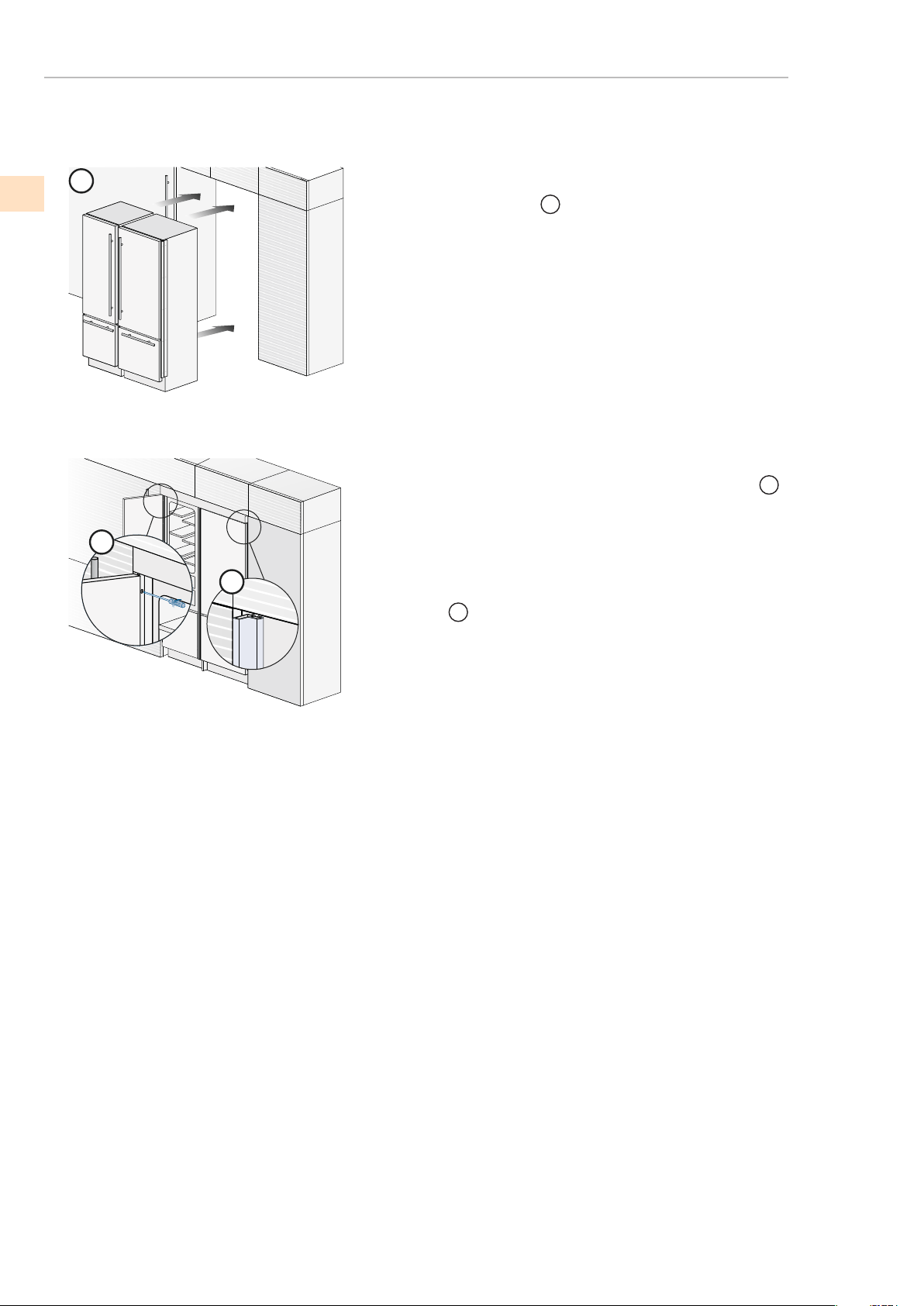
©2018 Hestan Commercial Corporation
5
7
6
(a continué)
EMPLACEMENT ET INSTALLATION
DÉPLACEMENT DU RÉFRIGÉRATEUR EN POSITION FINALE
Une fois complétés les passages ci-dessus, poussez les appareils dans
leur position dénitive
6
Il sera nécessaire de prévoir une cheminée de ventilation à l’arrière
de la niche pour garantir une ventilation adèquate. Un écart de 5 mm
est sufsant pour éviter tout surchauffement. Assemblez toujours les
panneaux frontaux à la porte et aux tiroirs avant de placer l’appareil
dans sa position dénitive dans la niche ou la structure.
Vérier que les pieds et les roues arrière soient à niveau avant d’en
-
castrer l’appareil.
Fixer chaque appareil aux meubles adjacents en vissant à ces der-
niers les prols latéraux, déjà montés sur les appareils
7
Pour effectuer facilement l’opération, garder la porte et le grand bac
ouverts.
Monter sur les prols les corniches de couverture, en les insérant la-
téralement
8
et puis en poussant avec force jusqu’au “clic” (comme
pour l’encastrement de l’appareil unique).
25
FR
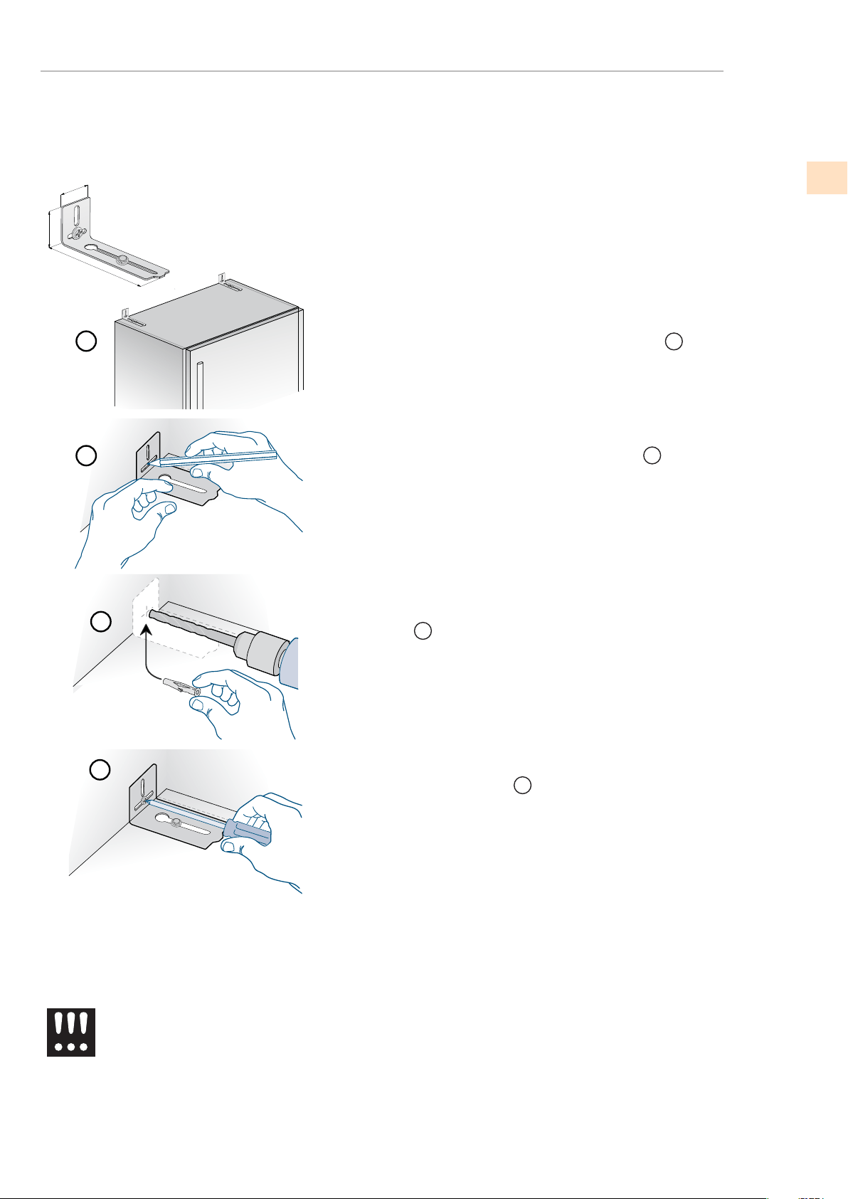
©2018 Hestan Commercial Corporation
26
152 (6”)
59 (
2
3⁄8
”)
45 (1
5⁄8
”)
1
2
3
4
MONTAGE DE LA SÉCURITÉ ANTI-RENVERSEMENT
An d’éviter tout risque de renversement de l’ap-
pareil, il est obligatoire de xer l’appareil au mur
moyennant deux équerres prévues à cet effet.
An d’éviter le risque de renversement de l’appareil lors de l’ouverture
de la porte et des bacs à pleine charge, l’installation de deux équer -
res qui xent la partie supérieure de l’appareil au mur est obligatoire.
Les équerres sont appliquées comme illustré à la gure en utilisant les
vis et les chevilles fournies.
Placer l’équerre sur la partie supérieure de l’appareil en correspon
-
dance des trous de xation et l’approcher au mur.
1
Marquer la position des trous avec un crayon.
2
Percer le mur avec une mèche de 8 mm (3/8”) et insérer la vis
tamponnée.
3
Replacer l’équerre et la xer d’abord sur la partie supérieure du
meuble et, ensuite, au mur.
4
(a continué)
EMPLACEMENT ET INSTALLATION
FR
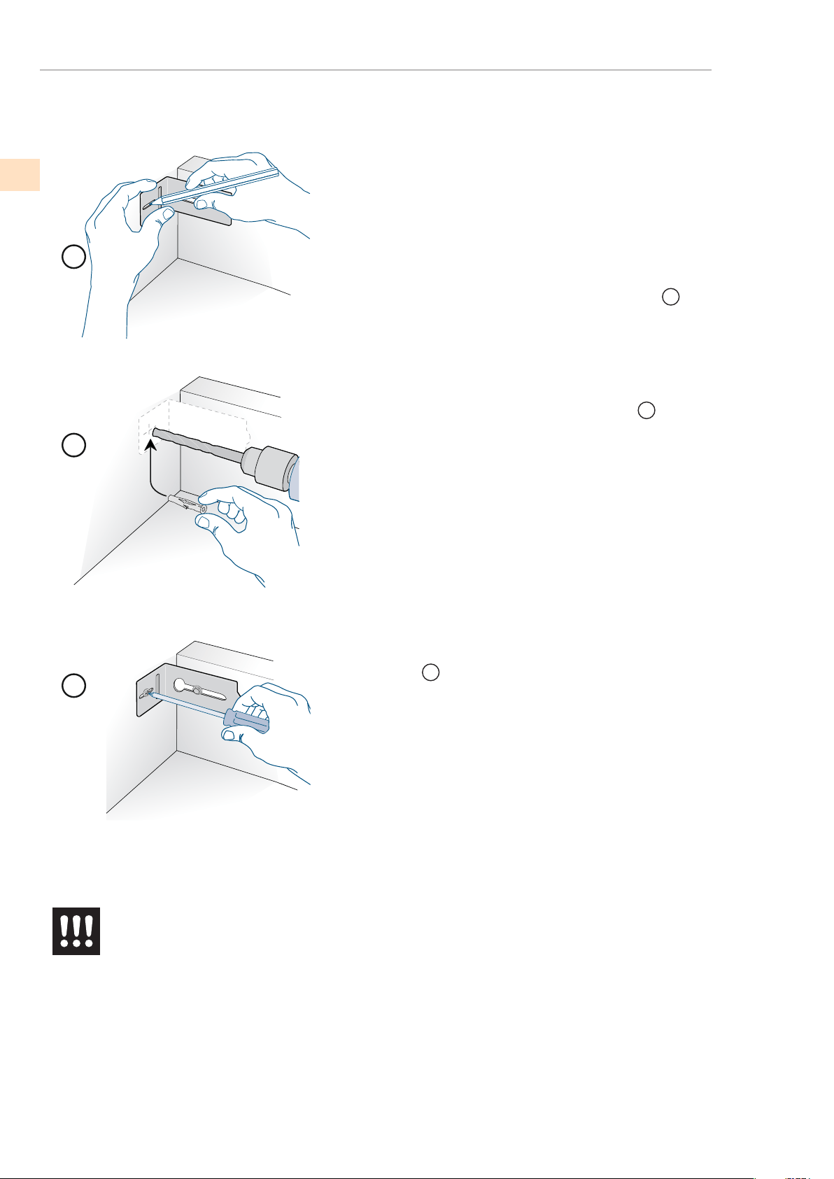
2
3
1
©2018 Hestan Commercial Corporation
1
2
3
(a continué)
EMPLACEMENT ET INSTALLATION
MONTAGE DE LA SÉCURITÉ ANTI-RENVERSEMENT
An d’éviter tout risque de renversement de
l’appareil, il est obligatoire de xer l’appa
-
reil au mur moyennant deux équerres pré-
vues à cet effet.
An d’éviter le risque de renversement de l’appareil lors de l’ouverture
de la porte et des bacs à pleine charge, l’installation de deux équer
-
res qui xent la partie supérieure de l’appareil au mur est obligatoire.
Les équerres sont appliquées comme illustré à la gure en utilisant les
vis et les chevilles fournies.
Placer l’équerre sur la partie supérieure de l’appareil en correspon
-
dance des trous de xation et l’approcher au mur.
Marquer la position des trous avec un crayon.
Percer le mur avec une mèche de 8 mm (3/8”) et insérer la vis
tamponnée.
Replacer l’équerre et la xer d’abord sur la partie supérieure du
meuble et, ensuite, au mur.
27
FR
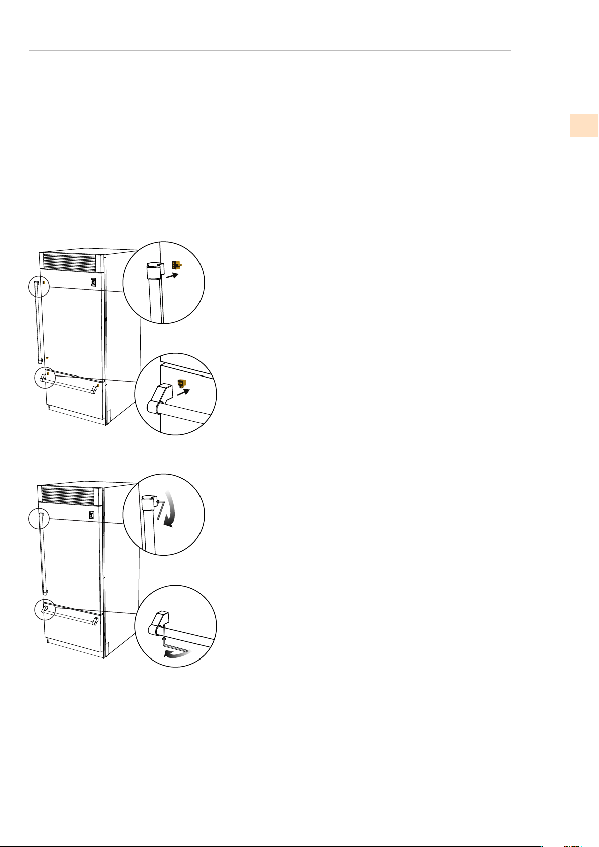
©2018 Hestan Commercial Corporation
28
MONTAGE DES POIGNÉES ET ENDCAPS
Les poignées et les embouts sont fournis avec tous les modèles en acier inoxydable et en couleur.
Les poignées sont situées dans un emballage protecteur, scotché à l'arrière du réfrigérateur.
Retirez les poignées avant déplacer le réfrigérateur dans sa découpe ou son ouverture. Les
embouts sont situés dans une boîte en carton à l'intérieur du réfrigérateur.
Il est recommandé que deux personnes travaillent ensemble pour assembler et appliquer les poignées
et embouts. Suivez les étapes ci-dessous pour terminer le processus de montage.
Insérez la poignée dans les embouts et positionnez les embouts sur
les supports qui sont pré-montés sur la porte et le tiroir. Utilisation
Attention à ne pas rayer la surface de la porte. Il est recommandé de
une personne tient la poignée et les embouts en position pendant que
la deuxième personne insère les vis de réglage fournies pour xer
manipuler.
Les vis de réglage fournies se trouvent dans la boîte avec les embouts.
À l'aide d'une clé hexagonale de 1/8 po (2,5 mm), insérez la vis de réglage
dans le trou dans le bouchon et resserrer soigneusement. Le bouchon est
alors correctement xé à la porte / tiroir. Répétez cette étape pour l'autre
embouts.
(a continué)
EMPLACEMENT ET INSTALLATION
FR
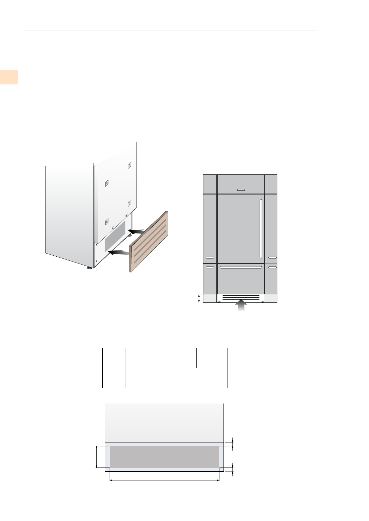
©2018 Hestan Commercial Corporation
VENTILATION REQUISE
860 (33 7/8”)
740 (29 1/8”)
560 (22”)
>100 (4”)
10 (3/8”)
30” Models
24” Models
100 (4”)
A
B
C
C
A
B
C
36” Models
CIRCULATION DE L’AIR
La grille de ventilation ne doit pas être bloqué ou couvert d’aucune
manière. Il doit aussi être dépoussiéré / nettoyés régulièrement.
Un système à air forcé assure la ventilation à travers la grille position
-
née dans la dans la partie inférieure de l’appareil. Si l’aménagement
de la cuisine prévoit une plinthe, cette dernière doit être trouée an
de garder un niveau d’aréation satisfaisant, comme expliqué dans le
dessin. Les trous peuvent être de toute sorte de forme et dimension, à
condition que la surface totale de la partie trouée est égale au 50%
de la surface de la plinthe.
Dans ce cas, pour permettre une meilleure aération, il est préferable
de retirer la grille frontale de l’ensemble. La grille est accrochée à
l’ensemble avec des plaques magnetiques et peut être facilement
retirée par l’utilisateur nal, an d’être nettoyée régulièrement de la
29
FR

©2018 Hestan Commercial Corporation
30
LISTE DE CONTRÔLE DE PRETEST
VENTILATION REQUISE
VENTILATION
(continued)
La ventilation est garantie par un système à air forcé à travers une
grille positionnée dans la partie haute de l’appareil.
Cette grille ne doit en aucun cas être couverte par des panneaux ou
autres dispositifs qui pourraient en réduire l’efcacité.
S’il vous plaît se référer à la page 5-6 pour assurer une circulation d’air
correcte.
MISE EN MARCHE
Contrôler que les pieds sont correctement installés.
Contrôler que le raccordement à l’installation hydrique ne présente
pas de fuites d’eau et que le robinet de fermeture est facilement ac
-
cessible.
Contrôler que le branchement électrique soit correctement réalisé
et que la che et l’interrupteur omnipolaire dédié soient facilement
accessibles.
Contrôler le parfait alignement de l’appareil avec les meubles ad
-
jacents.
Contrôler que chaque ruban adhésif ou protection temporaire in
-
terne ou externe soit éliminé.
Contrôler la parfaite étanchéité des portes et le coulissement des
bacs et des clayettes.
FR

©2018 Hestan Commercial Corporation
DÉMARRAGE INITIAL
(continued)
MISE EN MARCHE
Pour mettre en marche l’appareil, brancher la che au réseau
électrique: lorsque la porte est ouverte, apparaît sur le panneau de
commande le message “Stand-by”, alors que toutes les touches du
panneau sont éteintes.
Pour mettre en marche tous les compartiments de l’appareil, ap-
puyer pendant 3 secondes sur la touche Power
Le message “initial test” apparaîtra pendant environ 2 minutes, ensuite
les compresseurs seront actifs jusqu’à attendre la température prévue
en usine par défaut. Veuillez noter que cette opération pourrait durer
plusieurs heures.
Si l’appareil est fourni avec un appareil à glaçons avant de le mettre
en marche pour la première fois, veuillez vous assurer que la cartou -
che du ltre pour l’eau a bien été installée et effectuez un remplissage
du circuit hydraulique.
Pour toute autre information concernant le fonctionnement de
l’appareil, se référer au Mode d’emploi.
Si lors de la première mise en marche, n’appa
-
raît pas le message Stand-by, mais apparaissent
Fridge too warm, Fresco too warm, Freezer too
warm ou signaux sonores, cela signie que l’ap
-
pareil a déjà commencé la procédure de refroi
-
dissement.
Dans ce cas désactiver les éventuels messages
sonores en efeurant la touche Alarm, refermer la
porte et attendre que les températures program-
mées soient atteintes.
Il faut laisser l’unité atteindre la température de
fonctionnement vide et avec la porte et un tiroir fer
-
mé avant que les aliments sont stockés à l’intérieur.
31
FR

©2018 Hestan Commercial Corporation
NOTES / REMARQUES

Hestan Commercial Corporation
3375 E. La Palma Ave
Anaheim, CA 92806
(888) 905-7463
RETAIN THIS MANUAL FOR FUTURE REFERENCE
CONSERVEZ CE MANUEL POUR UNE RÉFÉRENCE FUTURE
©2018 Hestan Commercial Corporation P/N 020056 REV A