E-TAC
(GB
Series)
GC
Packaged
Terminal
Air
Conditioner
/
Heat
Pump
wD
GR
Ce
7,000
—
15,000
Btuh
Installation
and
Operating
Instructions
NOTE
TO
EQUIPMENT
OWNER:
Thank
you
for
purchasing
a
Gree
E-TAC.
Please
read
this
Owner’s
Information
Manual
carefully
before
installing
and
using
this
appliance.
Keep
this
manual
for
future
reference.
For
your
convenience,
please
record
the
model
and
serial
numbers
of
your
new
equipment
in
the
spaces
provided.
This
information,
along
with
the
installation
data
and
dealer
contact
information,
will
be
helpful
should
your
system
require
maintenance
or
service.
UNIT
INFORMATION
DEALERSHIP
CONTACT
INFORMATION
Model
#
Company
Name:
Serial
#
Address:
INSTALLATION
INFORMATION
Date
Installed
Phone
Number:
Technician
Name:
TABLE
OF
CONTENTS
PAGE
SAFETY
CONSIDERATIONS
00000
ee
ee
eee
3
GENERAL
INFORMATION,
oo
ee
ee
eee
3
UNIT
FEATURES
200
ee
eee
eee
ees
4-5
ELECTRICAL
DATA
11
ee
ee
eee
eee
6
INSTALLATION
Chassis
Installation
000.
ee
ee
ees
7
Retrofit
Sleeve
Preparation
2.0.0.
ee
eee
teen
eee
ee
8
Installation
of
Gree
Wall
Sleeve
Using
Non-Gree
Grille...
0
cee
eens
8
Install
Unit
Into
Wall
Sleeve...
ee
eee
eee
9
SYSTEM
CONFIGURATION
Ventilation
Control
6.
ee
eee
10
Adjusting
Air
Direction...
0.
e
teen
teens
10
Dipswitches 0.0
ee
ee ee
ee
enter
eee
11
Keypad
Configuration...
0.
eee
eee
ete
eee
12
AUXILIARY
CONTROLS
Wall
Thermostat
Terminal
0.0.
eee
eee
14
Energy
Management
Input...
0...
ee
eee
14
Intelligent
Self-Checking
Control
0...
eee
eee
teens
14
OPERATION
oe
ne
eee
eee
ees
15
CARE
AND
CLEANING
20
ee
ee
eee
ee
16
PREVENTATIVE
MAINTENANCE
20000
ee
ee
eee
17
TROUBLESHOOTING
000
eee
eee
18
-22
WARRANTY
20
ee
eee
eee
ee
eee
ee
23
-
24
NOTE:
Warranty
coverage
documented
on
back
page
of
owners
manual
UNIT
INSPECTION
Examine
unit
for
damage
incurred
during
shipment.
File
a
claim
immediately
with
the
transit
company
if
damage
is
found.
No
READ
ALL
INSTRUCTIONS
BEFORE
INSTALLATION
OR
USE
SAFETY
CONSIDERATIONS
Recognize
safety
information.
This
is
the
safety-alert
symbol
A\.
When
you
see
this
symbol
on
the
unit
and
in
instructions
or
manuals,
be
alert
to
the
potential
for
personal
injury.
Understand
these
signal
words:
DANGER,
WARNING,
and
CAUTION.
These
words
are
used
with
the
safety-alert
symbol.
DANGER
identifies
the
most
serious
hazards
which
will
result
in
severe
personalinjury
or
death.
WARNING
signifies
hazards
which
could
result
in
personal
injury
or
death.
CAUTION
is
used
to
identify
unsafe
practices
which
may
result
in
minor
personal
injury
or
product
and
property
damage.
NOTE
is
used
to
highlight
suggestions
which
will
result
in
enhanced
installation,
reliability,
or
operation.
4
WARNING
PERSONAL
INJURY
AND/OR
PROPERTY
DAMAGE
HAZARD
Failure
to
follow
this
warning
could
result
in
personal
injury,
death
and/or
property
damage.
For
your
safety,
the
information
in
this
manual
must
be
followed
to
minimize
the
risk
of
fire
or
explosion,
electric
shock,
or
to
prevent
property
damage,
personal
injury,
or
loss
of
life.
*
This
unit
must
be
properly
installed
in
accordance
with
the
Installation
Instructions
before
it
is
used.
*
Immediately
repair
or
replace
all
electric
service
cords
that
have
become
frayed
or
otherwise
damaged.
*
Unplug
or
disconnect
the
unit
at
the
fuse
box
or
circuit
breaker
before
making
any
repairs.
NOTE:
We
strongly
recommend
that
any
servicing
be
performed
by
a
qualified
individual.
GENERAL
Thank
you
for
choosing
the
Gree
ETAC!
You
can
feel
confident
in
your
selection
because
of
the
pride
in
craftsmanship
and
engineering
knowledge
that
goes
into
this
equipment.
Gree
package
terminal
air
conditioners
and
heat
pumps
provide
a
high
standard
of
quality
in
performance,
workmanship,
durability
and
appearance
as
they
heat
and
cool
the
occupied
air
space
year
round.
This
manual
provides
information
for
ease
of
installation,
operation
and
maintenance.
All
models
are
designed
for
through-the-wall
installation.
Separate
installation
instructions
are
included
with
all
accessory
components.
BEFORE
YOU
BEGIN
Read
these
instructions
completely
and
carefully.
IMPORTANT:
Save
these
instructions
for
local
inspector’s
use.
IMPORTANT:
Observe
all
governing
codes
and
ordinances.
NOTE
TO
INSTALLER
Be
sure
to
leave
these
instructions
with
the
owner.
NOTE
TO
OWNER
Keep
these
instructions
for
future
reference.
Be
sure
to
write
down
the
model
and
serial
number
of
unit
on
space
provided
on
front
page.
The
model
and
serial
number
can
be
located
on
the
serial
number
plate
attached
to
unit.
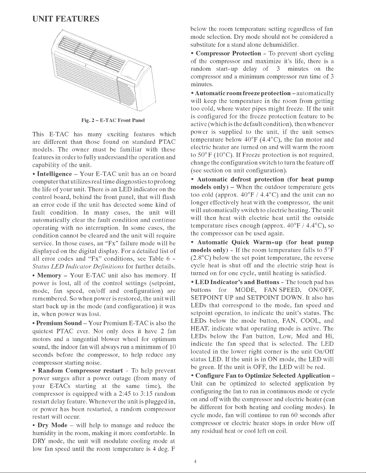
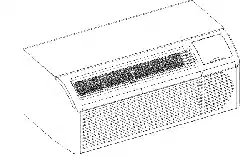
UNIT
FEATURES
Fig.
2
—-
E-TAC
Front
Panel
This
E-TAC
has
many
exciting
features
which
are
different
than
those
found
on
standard
PTAC
models.
The
owner
must
be
familiar
with
these
features
in
order
to
fully
understand
the
operation
and
capability
of
the
unit.
*
Intelligence
—
Your
E-TAC
unit
has
an
on
board
computer
that
utilizes
real
time
diagnostics
to
prolong
the
life
of
your
unit.
There
is
an
LED
indicator
on
the
control
board,
behind
the
front
panel,
that
will
flash
an
error
code
if
the
unit
has
detected
some
kind
of
fault
condition.
In
many
cases,
the
unit
will
automatically
clear
the
fault
condition
and
continue
operating
with
no
interruption.
In
some
cases,
the
condition cannot
be
cleared
and
the
unit will
require
service.
In
those
cases,
an
“Fx”
failure
mode
will
be
displayed
on
the
digital
display.
For
a
detailed
list
of
all
error
codes
and
“Fx”
conditions,
see
Table
6
-
Status
LED
Indicator
Definitions
for
further
details.
«
Memory
—
Your
E-TAC
unit
also
has
memory.
If
power
is
lost,
all
of
the
control
settings
(setpoint,
mode,
fan
speed,
on/off
and
configuration)
are
remembered.
So
when
power
is
restored,
the
unit
will
start
back
up
in
the
mode
(and
configuration)
it
was
in,
when
power
was
lost.
¢
Premium
Sound
—
Your
Premium
E-TAC
is
also
the
quietest
PTAC
ever.
Not
only
does
it
have
2
fan
motors
and
a
tangential
blower
wheel
for
optimum
sound,
the
indoor
fan will
always
run
a
minimum
of
10
seconds
before
the
compressor,
to
help
reduce
any
compressor
starting noise.
*
Random
Compressor
restart
-
To
help
prevent
power
surges
after
a
power
outage
(from
many
of
your
E-TACs
starting
at
the
same
time),
the
compressor
is
equipped
with
a
2:45
to
3:15
random
restart
delay
feature.
Whenever
the
unit
is
plugged
in,
or
power
has
been
restarted,
a
random
compressor
restart
will
occur.
«
Dry
Mode
—
will
help
to
manage
and
reduce
the
humidity
in
the
room,
making
it
more
comfortable.
In
DRY
mode,
the
unit
will
modulate
cooling
mode
at
low
fan
speed
until
the
room
temperature
is
4
deg.
F
below
the
room
temperature
setting
regardless
of
fan
mode
selection.
Dry
mode
should
not
be
considered
a
substitute
for
a
stand
alone
dehumidifier.
*
Compressor
Protection
-
To
prevent
short
cycling
of
the
compressor
and
maximize
it’s
life,
there
is
a
random
start-up
delay
of
3
minutes
on
the
compressor
and
a
minimum
compressor
run
time
of
3
minutes.
*
Automatic
room
freeze
protection
—
automatically
will
keep
the
temperature
in
the
room
from
getting
too
cold,
where
water
pipes
might
freeze.
If
the
unit
is
configured
for
the
freeze
protection
feature
to
be
active
(which
is
the
default
condition),
then
whenever
power
is
supplied
to
the unit,
if
the
unit
senses
temperature
below
40°F
(4.4°C),
the
fan
motor
and
electric
heater
are
turned
on
and
will
warm
the
room
to
50°F
(10°C).
If
Freeze
protection
is
not
required,
change
the
configuration
switch
to
turn
the
feature
off
(see
section
on
unit
configuration).
*
Automatic
defrost
protection
(for
heat
pump
models
only)
—
When
the
outdoor
temperature
gets
too
cold
(approx.
40°F
/
4.4°C)
and
the
unit
can
no
longer
effectively
heat
with
the
compressor,
the
unit
will
automatically
switch
to
electric
heating.
The
unit
will
then
heat
with
electric
heat
until
the
outside
temperature
rises
enough
(approx.
40°F
/
4.4°C),
so
the
compressor
can
be
used
again.
*
Automatic
Quick
Warm-up
(for
heat
pump
models
only)
-
If
the
room
temperature
falls
to
5°F
(2.8°C)
below
the
set
point
temperature,
the
reverse
cycle
heat
is
shut
off
and
the
electric
strip
heat
is
turned
on
for
one
cycle,
until
heating
is
satisfied.
*
LED
Indicator’s
and
Buttons
-
The
touch
pad
has
buttons
for
MODE,
FAN
SPEED,
ON/OFF,
SETPOINT
UP
and
SETPOINT
DOWN.
It
also
has
LEDs
that
correspond
to
the
mode,
fan
speed
and
setpoint
operation,
to
indicate
the
unit’s
status.
The
LEDs
below
the
mode
button,
FAN,
COOL,
and
HEAT,
indicate
what
operating
mode
is
active.
The
LEDs
below
the
Fan
button,
Low,
Med
and
Hi,
indicate
the
fan
speed
that
is
selected.
The
LED
located
in
the
lower
right
corner
is
the
unit
On/Off
status
LED.
If
the
unit
is
in
ON
mode,
the
LED
will
be
green.
If
the
unit
is
OFF,
the
LED
will
be
red.
*
Configure
Fan
to
Optimize
Selected
Application
—
Unit
can
be
optimized
to
selected
application
by
configuring
the
fan
to
run
in
continuous
mode
or
cycle
on
and
off
with
the
compressor
and
electric
heater
(can
be
different
for
both
heating
and
cooling
modes).
In
cycle
mode,
fan
will
continue
to
run
60
seconds
after
compressor
or
electric
heater
stops
in
order
blow
off
any
residual
heat
or
cool
left
on
coil.
UNIT
FEATURES
CONTINUED
«
Unit
Configuration
—
There
are
many
different
configuration
possibilities,
through
both
dipswitches
and
the
digital
keypad,
that
allow
you
to
configure
the
unit
for
your
exact
application.
See
section
on
unit
configuration
for
more
details.
Following
are
the
configuration
selections
that
have
not
previously
been
mentioned:
¢
Fahrenheit
°F
or
Celcious
°C
—
The
unit
can
display
in
either
°F
or
°C.
¢
Indoor
Temperature
Sensor
Biasing
—
Optimize
the
room
temperature
sensor
reading
to
your
exact
application
(one
for
cooling
and
another
for
heating).
«
Emergency
Heat
(for
Heat
Pump
Only)
—
Disable
the
compressor
during
heating
mode
operation
(heat
only
with
Electric
Heat).
*«
Display
Setpoint
or
Room
Temperature
—
The
unit
can
be
configured
to
display
the
room
temperature
OR
setpoint
only,
during
heating
and
cooling
modes.
See
section
on
unit
configuration
for
more
details.
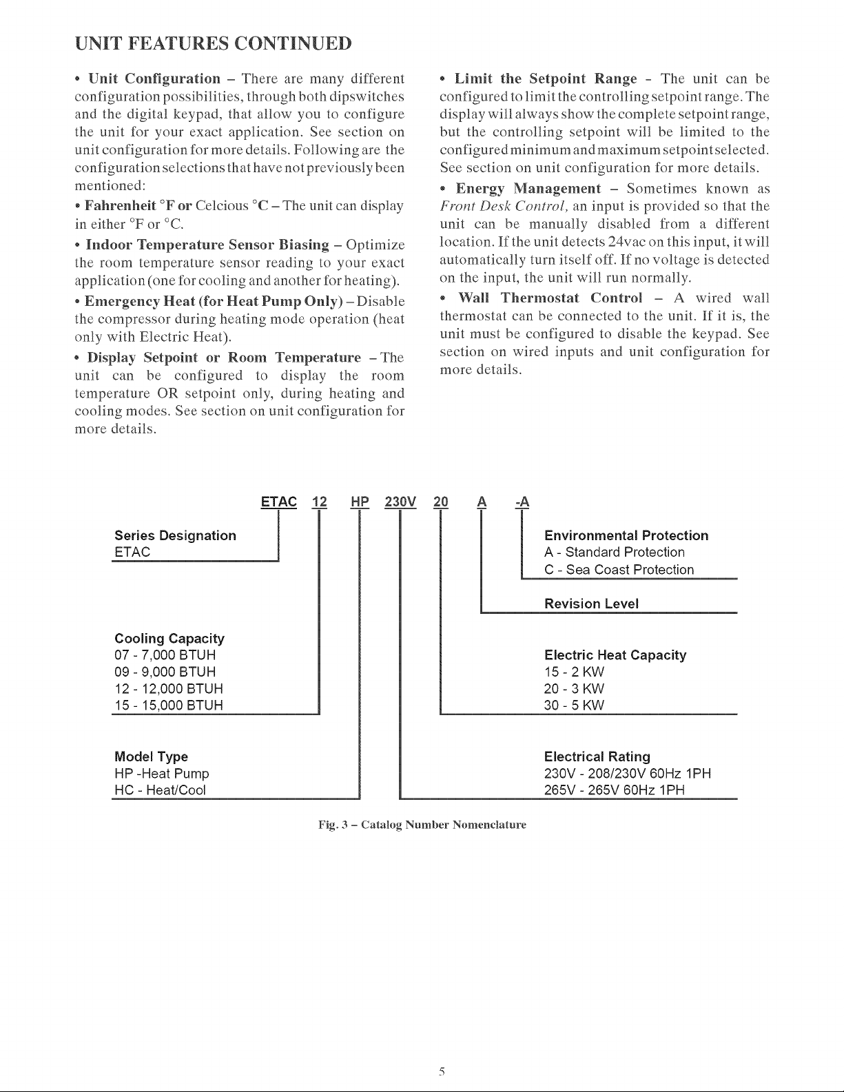
Series
Designation
ETAC
Cooling
Capacity
07
-
7,000
BTUH
09
-
9,000
BTUH
12
-
12,000
BTUH
15
-
15,000
BTUH
Model
Type
HP
-Heat
Pump
HC
-
Heat/Cool
*
Limit
the
Setpoint
Range
-
The
unit
can
be
configured
to
limit
the
controlling
setpoint
range.
The
display
will
always
show
the
complete
setpoint
range,
but
the
controlling
setpoint
will
be
limited
to
the
configured
minimum
and
maximum
setpointselected.
See
section
on
unit
configuration
for
more
details.
«
Energy
Management
—
Sometimes
known
as
Front
Desk
Control,
an
input
is
provided
so
that the
unit
can
be
manually
disabled
from
a
different
location.
Ifthe
unit
detects
24vac
on
this
input,
it
will
automatically
turn
itself
off.
If
no
voltage
is
detected
on
the
input,
the
unit will
run
normally.
e
Wall
Thermostat
Control
—
A
wired
wall
thermostat
can
be
connected
to
the
unit.
Ef
it
is,
the
unit
must
be
configured
to
disable
the
keypad.
See
section
on
wired
inputs
and
unit
configuration
for
more
details.
in
iS
i
b
Environmental
Protection
A-
Standard
Protection
C
-
Sea
Coast
Protection
Revision
Level
Electric
Heat
Capacity
15-2KW
20-3
KW
30-5
KW
Electrical
Rating
230V
-
208/230V
60Hz
1PH
265V
-
265V
60Hz
1PH
Fig.
3
—
Catalog
Number
Nomenclature
ELECTRICAL
DATA
ELECTRICAL
SHOCK
HAZARD
Failure
to
follow
this
warning
could
result
in
personal
injury
or
death
and/or
property
damage
DO
NOT
alter
cord
or
plug
or
use
an
extension
cord.
IMPORTANT:
For
265V
units,
if
power
cord
accessory
option
is
selected,
the
cord
is
only
18
inches
long
and
must
plug
into
the
accessory
electrical
265V
subbase.
Be
sure
that
your
outlet
matches
the
appropriate
blade
configuration
of
the
plug
and
that
it
is
within
reach
of
the
service
cord.
All
wiring,
including
installation
of
the
receptacle,
must
be
in
accordance
with
the
NEC
and
local
codes,
ordinances
and
regulations.
National
codes
require
the
use
of
an
arc
fault
or
leakage
current
detection
device
on
all
208/230V
power
cords.
Be
sure
to
select
the
correct
cord
for
your
installation.
ALL
UNITS
Wire
Size
Use
recommended
wire
size
given
in
Table
1
and
install
a
single
branch
circuit.
All
wiring
must
comply
with
local
and
national
codes.
All
units
are
designed
to
operate
off
ONE
single
branch
circuits
only.
NOTE:
Use
copper
conductors
only.
Table
1—SUGGESTED
BRANCH
CIRCUIT
WIRE
SIZES*
NAMEPLATE
AMPS
AWG
WIRE
SIZEt
7.0
to
12
14
12.1
to
16
12
16.1
to
24
10
LEGEND
AWG
—
American
Wire
Gauge
*
Single
circuit
from
main
box.
t+
Based
on
copper
wire
at
60°C
temperature
rating.
Grounding
For
safety
and
protection,
the
unit
is
grounded
through
the
service
cord
plug
or
through
separate
ground
wire
provided
on
hard
wired
units.
Be
sure
that
the
branch
circuit
or
general
purpose
outlet
is
grounded.
VOLTAGE
SUPPLY
Check
voltage
supply
at
outlet.
For
satisfactory
results,
the
voltage
range
must
always
be
within
the
ranges
found
on
the
data
information
plate.
Cord-connected
Units
The
208/230-v
field
supplied
outlet
must
match
the
plug
for
the
standard
208/230
-v
units
and
be
within
reach
of
the
service
cord.
The
standard
cord-connected
265-v
units
require
an
accessory
electrical
subbase
for
operation.
Refer
to
Table
2
for
proper
receptacle
and
fuse
type.
Power
Cord
Protection
The
power
cord
for
208/230v
units
provide
power
cord
fire
protection.
Unit
power
automatically
disconnects
when
unsafe
conditions
are
detected.
Power
to
the
unit
can
be
restored
by
pressing
the
reset
button
on
plug
head.
Upon
completion
of
unit
installation
for
208/230V
models,
an
operational
check
should
be
performed
using
the
TEST/RESET
buttons
on
the
plug
head.
NOTE:
The
265v
models
do
not
incorporate
this
feature
as
they
require
use
of
the
electrical
subbase
accessory.
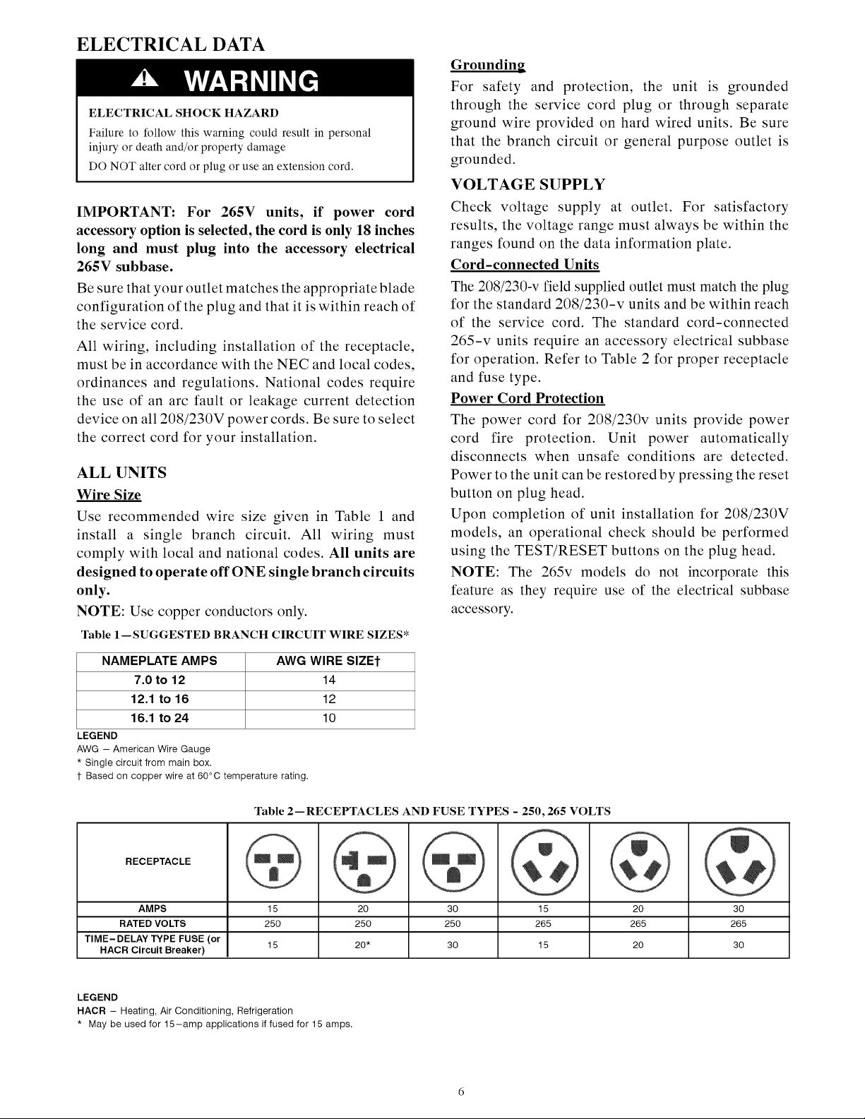
Table
2—RECEPTACLES
AND
FUSE
TYPES
-
250,
265
VOLTS
HACR
Circuit
Breaker)
RECEPTACLE
AMPS
15
20 30
15
20 30
RATED
VOLTS
250
250 250 265 265 265
TIME-DELAY
TYPE
FUSE
(or
15
20*
30
15
20 30
LEGEND
HACR
-—
Heating,
Air
Conditioning,
Refrigeration
*
May
be
used
for
15—amp
applications
if
fused
for
15
amps.
INSTALLATION
Proper
installation
is
the
responsibility
of
the
installer.
Product
failure
due
to
improper
installation
is
not
covered
under
the
Warranty.
UNIT
DAMAGE
AND/OR
OPERATION
HAZARD
Failure
to
follow
this
caution
may
result
in
equipment
damage
or
improper
operation.
CHASSIS
INSTALLATION
Units
are
shipped without
a
sleeve.
In
applications
where
unit
is
a
replacement,
it
is
recommended
that
a
Gree
sleeve
be
used.
For
retrofit
applications,
foam
seals
on
outdoor
coil
tube
sheets
must
make
a
seal
between
the
coil
and
the
grille
or
loss
of
performance
and
premature
damage
to
the
major
components
can
result.
These
units
can
retrofit
Carrier,
General
Electric,
Amana,
Trane,
and
Friedrich
sleeves/grilles
(be
sure
Table
3—
Retrofit
Wall
Sleeves
outdoor
grille
is
installed
on
the
sleeve).
See
Table
3
Manufacturer
Wall
Sleeve
Part
Number
for
details.
Gree
engineering
must
approve
any
other
retrofit
application.
General
Electric
Metal
Sleeve
RAB71
Plastic
Sleeve
RAB77
Metal
Sleeve
WS900D
Metal
Sleeve
-
SLEEVE-STEEL-1PK
Plastic
Sleeve
-
WALL-SLEEVE-1PK
Metal
Sleeve
SLV149
For
competitive
retrofit
applications,
be
sure
that
the
Amana
foam
seals
(factory-installed
on
the
tube
sheets)
Carrier
provide
a
good
seal
between
the
grille
and
outdoor
coil
tube
sheets.
These
foam
seals
provide
a
barrier
to
Trane
separate
outdoor
coil
leaving
air
from
mixing
with
Friedrich
the
outdoor
incoming
air
(known
as
air
recircula-
tion).
T-Series
Metal
11-1/2”
(292.1
mm)
Deep
Wall
Sleeve*
Standard
Depth
Wall
Sleeve
16
X
42
X
139/4—
in.
(406.4
X
1067
X
349.3
mm)
PXWS
*
FR-SLEEVE—-EXT
accessory
is
required
for
retrofit
into
Friedrich
(T-Series)
wall
sleeves.
Minimum
wall
sleeve
opening
must
be
greater
than
14.75
X
40.00
in.
(374.7
x
1016
mm)
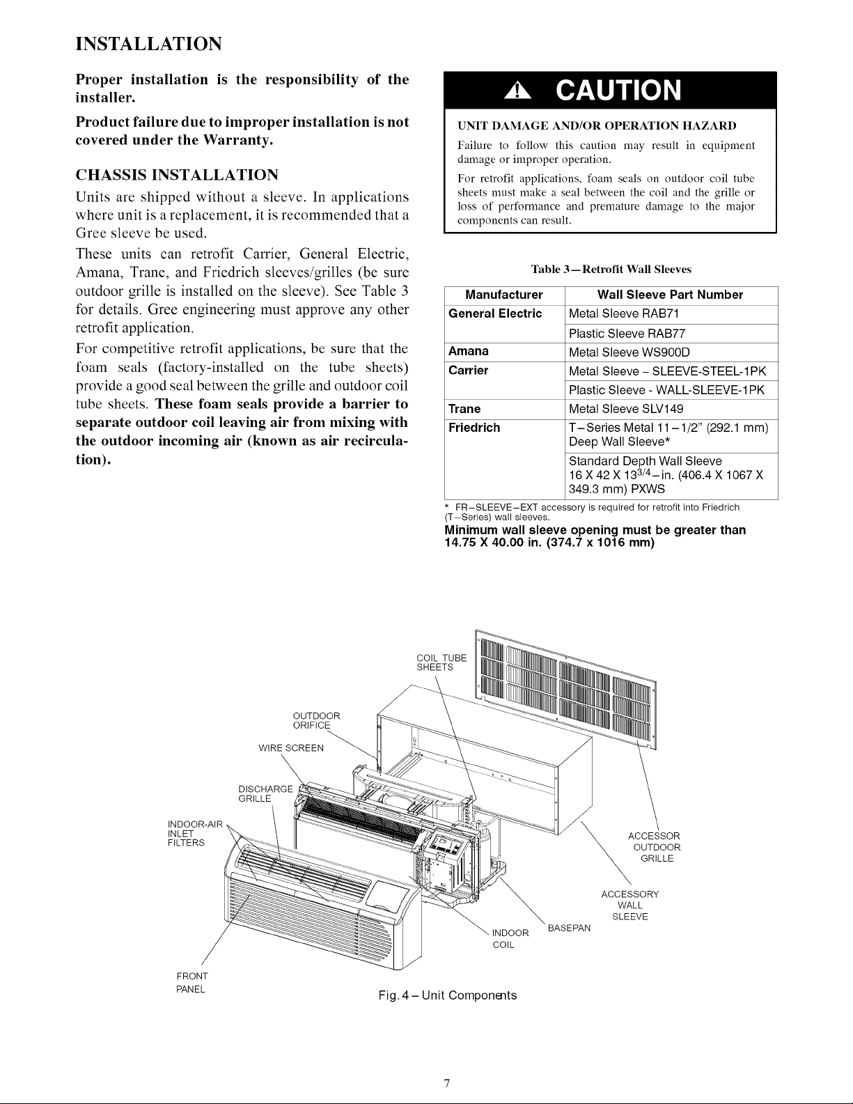
COIL
TUBE
SHEETS
OUTDOOR
ORIFICE
WIRE
SCREEN
DISCHARGE
GRILLE
INDOOR-AIR
INLET
FILTERS
Fig.
4-—Unit
Components
ACCESSOR
OUTDOOR
GRILLE
ACCESSORY
BASEPAN
RETROFIT
SLEEVE
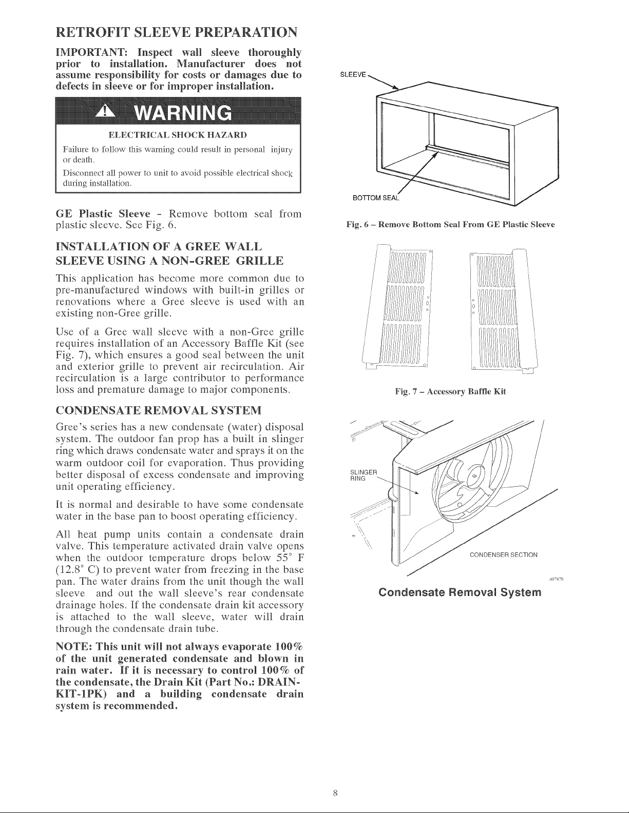
PREPARATION
IMPORTANT:
Inspect
wall
sleeve
thoroughly
prior
to
installation.
Manufacturer
does
not
assume
responsibility
for
costs
or
damages
due
to
SLEEVE
defects
in
sleeve
or
for
improper
installation.
ELECTRICAL
SHOCK
HAZARD
Failure
to
follow
this
warning
could
result
in
personal
injury
or
death.
Disconnect
all
power
to
unit
to
avoid
possible
electrical
shock
during
installation.
BOTTOM
SEAL
GE
Plastic
Sleeve
-
Remove
bottom
seal
from
plastic
sleeve.
See
Fig.
6.
Fig.
6
—
Remove
Bottom
Seal
From GE
Plastic
Sleeve
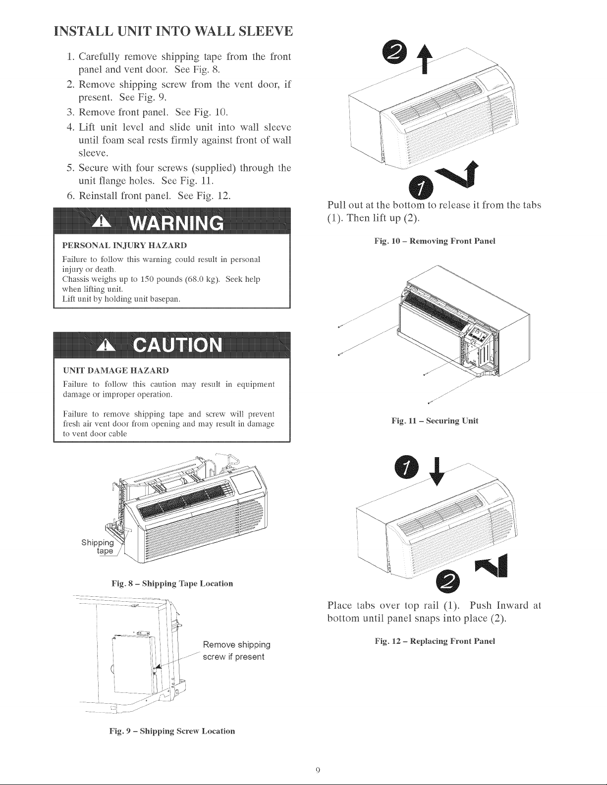
INSTALLATION
OF
A
GREE
WALL
SLEEVE
USING
A
NON-GREE
GRILLE
This
application
has
become
more
common
due
to
pre-manufactured
windows
with
built-in
grilles
or
renovations
where
a
Gree
sleeve
is
used
with
an
existing
non-Gree
grille.
|
=
—
E
ce
&
~~
S
Oo
Use
of
a
Gree
wall
sleeve
with
a
non-Gree
grille
requires
installation
of
an
Accessory
Baffle
Kit
(see
Fig.
7),
which
ensures
a
good
seal
between
the
unit
and
exterior
grille
to
prevent
air
recirculation.
Air
A
recirculation
is
a
large
contributor
to
performance
/
loss
and
premature
damage
to
major
components.
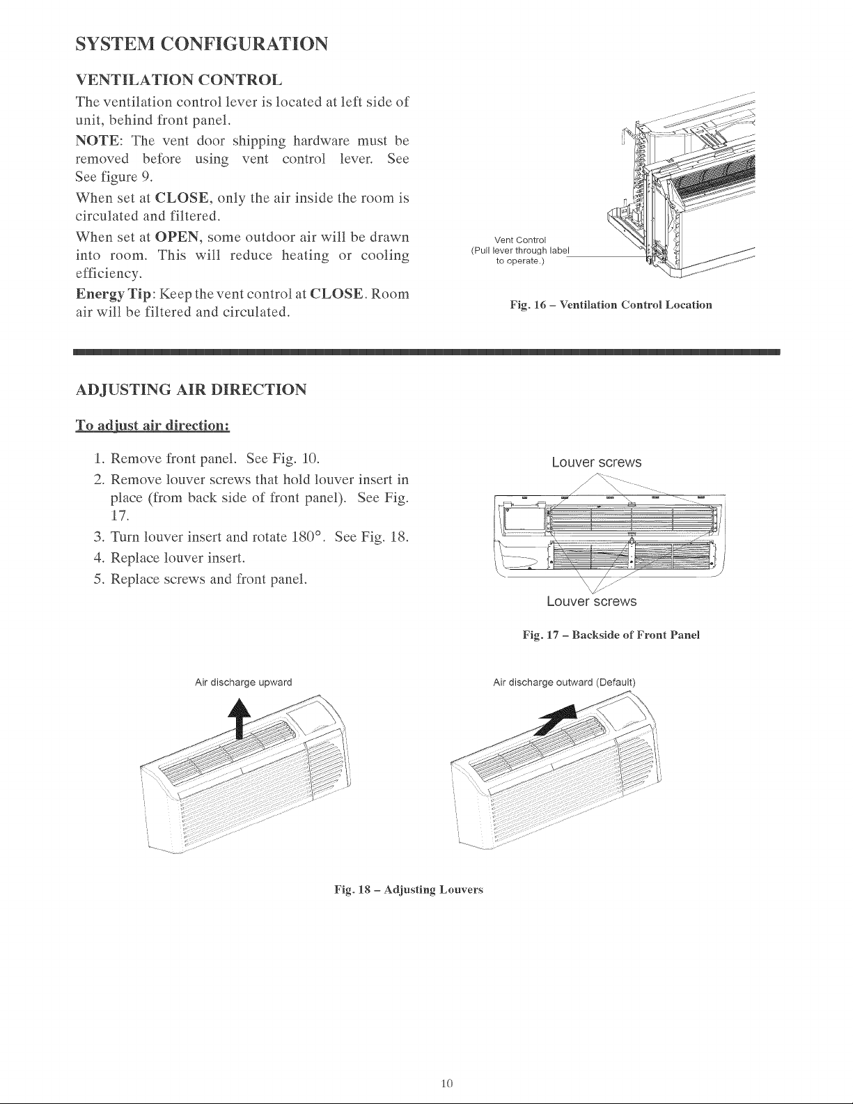
CONDENSATE
REMOVAL
SYSTEM
Gree’s
series has
a
new condensate
(water)
disposal
system.
The
outdoor
fan
prop
has
a
built
in
slinger
ring
which
draws
condensate
water
and
sprays
it
on
the
warm
outdoor
coil
for
evaporation.
Thus
providing
better
disposal
of
excess
condensate
and
improving
Su
GER
unit
operating
efficiency.
It
is
normal
and
desirable
to
have
some
condensate
water
in
the
base
pan
to
boost
operating
efficiency.
All
heat
pump
units
contain
a
condensate
drain
valve.
This
temperature
activated
drain
valve
opens
when
the
outdoor
temperature
drops
below
55°
F
(12.8°
C)
to
prevent
water
from
freezing
in
the
base
pan.
The
water
drains
from
the
unit
though
the
wall
sleeve
and
out
the
wall
sleeve’s
rear
condensate
Condensate
Removal
System
drainage
holes.
If
the
condensate
drain
kit
accessory
is
attached
to
the
wall
sleeve,
water
will
drain
through
the
condensate
drain
tube.
CONDENSER
SECTION
ALTGTS
NOTE:
This
unit
will
not
always
evaporate
100%
of
the
unit
generated
condensate
and
blown
in
rain
water.
If
it
is
necessary
to
control
100%
of
the
condensate,
the
Drain
Kit
(Part
No.:
DRAIN-
KIT-IPK)
and
a
building
condensate
drain
system
is
recommended.
INSTALL
UNIT
INTO
WALL
SLEEVE
1.
Carefully
remove
shipping
tape
from
the
front
panel
and
vent
door.
See
Fig.
8.
2.
Remove
shipping
screw
from
the
vent
door,
if
present.
See
Fig.
9.
3.
Remove
front
panel.
See
Fig.
10.
4.
Lift
unit
level
and
slide unit
into
wall
sleeve
until
foam
seal
rests
firmly
against
front
of
wall
sleeve.
5.
Secure
with
four
screws
(supplied)
through
the
unit
flange
holes.
See
Fig.
11.
6.
Reinstall
front
panel.
See
Fig.
12.
Pull
out
at
the
bottom
to
release
it
from
the
tabs
4
WARNING
(1).
Then
lift
up
(2).
Fig.
10
—-
Removing
Front
Panel
PERSONAL
INJURY
HAZARD
Failure
to
follow
this
warning
could
result
in
personal
injury
or
death.
Chassis
weighs
up
to
150
pounds
(68.0
kg).
Seek
help
when
lifting
unit.
Lift
unit
by
holding
unit
basepan.
4
CAUTION
UNIT
DAMAGE
HAZARD
Failure
to
follow
this
caution
may
result
in
equipment
a
damage
or
improper
operation.
a
Failure
to
remove
shipping
tape
and
screw
will
prevent
fresh
air
vent
door
from
opening
and
may
result
in
damage
to
vent
door
cable
Fig.
11
—
Securing
Unit
Place
tabs
over
top
rail
(1).
Push
Inward
at
bottom
until
panel
snaps
into
place
(2).
Remove
shipping
Fig.
12
—-
Replacing
Front
Panel
-~
screw
if
present
Fig.
9
—
Shipping
Screw
Location
SYSTEM
CONFIGURATION
VENTILATION
CONTROL
The
ventilation
control
lever
is
located
at
left
side
of
unit,
behind
front
panel.
NOTE:
The
vent
door
shipping
hardware
must
be
removed
before
using
vent
control
lever.
See
See
figure
9.
When
set
at
CLOSE,
only
the
air
inside
the
room
is
circulated
and
filtered.
When
set
at
OPEN,
some
outdoor
air
will
be
drawn
into
room.
This
will
reduce
heating
or
cooling
efficiency.
Energy
Tip:
Keep
the
vent
control
at
CLOSE.
Room
air
will
be
filtered
and
circulated.
Vent
Control
(Pull
lever
through
label
to
operate.)
Fig.
16
—
Ventilation
Control
Location
ADJUSTING
AIR
DIRECTION
To
adjust
air
direction:
1.
Remove
front
panel.
See
Fig.
10.
2.
Remove
louver
screws
that
hold
louver
insert
in
place
(from
back
side
of
front
panel).
See
Fig.
17.
3.
Turn
louver
insert
and
rotate
180°.
See
Fig.
18.
4,
Replace
louver
insert.
5.
Replace
screws
and
front
panel.
Air
discharge
upward
Louver
screws
Louver
screws
Fig.
17
—
Backside
of
Front
Panel
Air
discharge
outward
(Default)
Fig.
18
—
Adjusting
Louvers
10
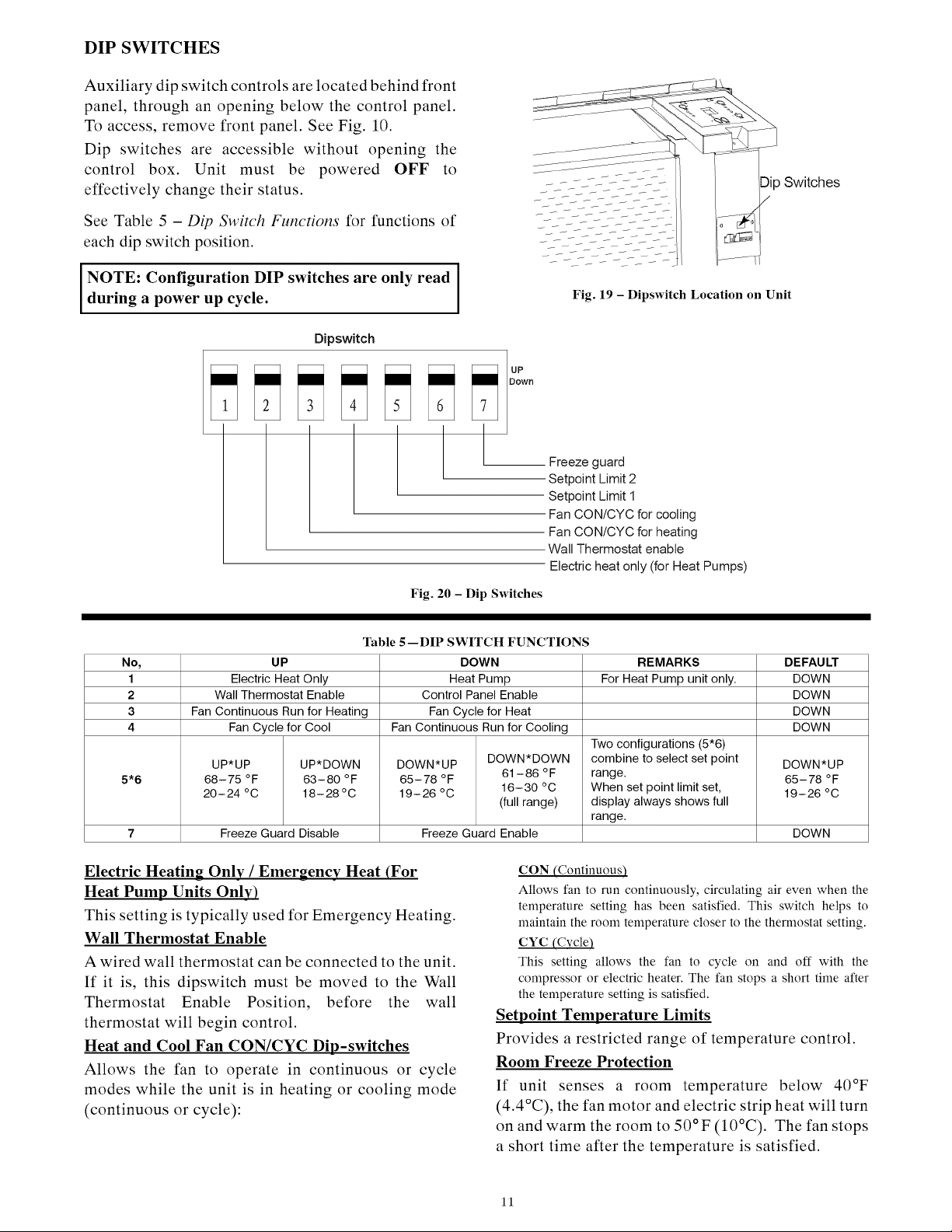
DIP
SWITCHES
Auxiliary
dip
switch
controls
are
located
behind
front
panel,
through
an
opening
below
the
control
panel.
To
access,
remove
front
panel.
See
Fig.
10.
Dip
switches
are
accessible
without
opening
the
control
box.
Unit
must
be
powered
OFF
to
effectively
change
their
status.
See
Table
5
—
Dip
Switch
Functions
for
functions
of
each
dip
switch
position.
NOTE:
Configuration
DIP
switches
are
only
read
during
a
power
up
cycle.
Fig.
19
—
Dipswitch
Location
on
Unit
Dipswitch
a
es
|
Cup
Down
a
Freeze
guard
Setpoint
Limit
2
Setpoint
Limit
1
Fan
CON/CYC
for
cooling
Fan
CON/CYC
for
heating
Wall
Thermostat
enable
Electric
heat
only
(for
Heat
Pumps)
Fig.
20
—
Dip
Switches
eee
eee
eee
ee
ee
ee
ee
ee
ee
ee
eee
Table
5—
DIP
SWITCH
FUNCTIONS
No,
UP
DOWN
REMARKS
DEFAULT
1
Electric
Heat Only Heat
Pump
For
Heat
Pump
unit
only.
DOWN
2
Wall
Thermostat
Enable
Control
Panel
Enable
DOWN
3
Fan
Continuous
Run
for
Heating
Fan
Cycle
for
Heat
DOWN
4
Fan
Cycle
for
Cool
Fan
Continuous
Run
for
Cooling
DOWN
Two
configurations
(5*6)
UP*UP
UP*DOWN
DOWN*UP
DOWN*DOWN
combine
to
select
set
point
DOWN*UP
5*6
68-75
°F
63-80
°F
65-78
°F
61-86
°F
range.
ae
65-78
°F
20-24
°C
18-28°C
19-26°C
16-30
°C
When
set
point
limit
set,
19-26°C
(full
range)
display
always
shows
full
range.
7
Freeze
Guard
Disable
Freeze
Guard
Enable
DOWN
Electric
Heating
Onlv
/
Emergency
Heat
(For
Heat
Pump
Units
Only)
This
setting
is
typically
used
for
Emergency
Heating.
Wall
Thermostat
Enable
A
wired
wall
thermostat
can
be
connected
to
the
unit.
If
it
is,
this
dipswitch
must
be
moved
to
the
Wall
Thermostat
Enable
Position,
before
the
wall
thermostat
will
begin
control.
Heat
and
Cool
Fan
CON/CYC
Dip-switches
Allows
the
fan
to
operate
in
continuous
or
cycle
modes
while
the
unit
is
in
heating
or
cooling
mode
(continuous
or
cycle):
CON
(Continuous)
Allows
fan
to
run
continuously,
circulating
air
even
when
the
temperature
setting
has
been
satisfied.
This
switch
helps
to
maintain
the
room
temperature
closer
to
the
thermostat
setting.
CYC
(Cycle
This
setting
allows
the
fan
to
cycle
on
and
off
with
the
compressor
or
electric
heater.
The
fan
stops
a
short
time
after
the
temperature
setting
is
satisfied.
Setpoint
Temperature
Limits
Provides
a
restricted
range
of
temperature
control.
Room
Freeze
Protection
If
unit
senses
a
room
temperature
below
40°F
(4.4°C),
the
fan
motor
and
electric
strip
heat
will
turn
on
and
warm
the
room
to
50°F
(10°C).
The
fan
stops
a
Short
time
after
the
temperature
is
satisfied.
11
KEYPAD
CONFIGURATION
Kevpad
Configuration
Allows
further
configuration
of
system
to
desired
application.
Changes
do
not
take
affect
until
power
is
cycled
on
the
unit.
To
enter
Keypad
configuration
Cycle
power
to
unit.
Press
and
hold
the
Fan
Speed
Button
and
the
COOLER
button
for
5
continuous
seconds,
within
30
seconds
of
the
unit
being
powered
up.
If
the
unit
has
had
power
for
more
than
30
continuous
seconds,
keypad
configuration
cannot
be
entered.
When
keypad
configuration
mode
is
first
entered,
it
will
default
to
Fahrenheit/
Celsius
Display
Mode.
‘To
scroll
through
the
Keypad
Configuration
Options
Press
and
release
the
Fan
Speed
button.
The
stored
value
will
be
displayed.
To
modify
configuration
settings
Press
and release
the
Setpoint
Up
or
Setpoint
Down
buttons.
To
exit
Keypad
Configuration
Keypad
Configuration
will
end
on
its
own
30
seconds
after
the
last
button
press
or
when
the
MODE
button
on
the
Keypad
is
pressed.
Fahrenheit/
Celsius
Display
Switch:
Change
between
degrees
Fahrenheit
and
Celsius
on
the
display.
An
“F”
indicates
Fahrenheit
display
and
‘C’
indicates
Celsius.
Default
is
degrees
“F”.
Indoor
Air
Temperature
Sensor
Biasing
for
Cooling
mode:
Sometimes
known
as
an
anticipator,
the
air
temperature
sensor
bias
is
used
to
adjust
the
room
air
temperature
reading
when
in
cooling
mode.
(Not
normally
required.)
Default
biasing
value
is
zero.
The
range
for
biasing
change
is
-6
deg
F
to
+6
deg
F
(-3
deg
C
to
+3
deg
C)
Indoor
Air
Temperature
Sensor
Biasing
for
Heating
mode:
Sometimes
known
as
an
anticipator,
the
air
temperature
sensor
bias
is
used
to
adjust
the
room
air
temperature
reading
when
in
heating
mode.
(Not
normally
required.)
Default
biasing
value
is
zero.
The
range
for
biasing
change
is
-6
deg
F
to
+6
deg
F
(-3
deg
C
to
+3
deg
C)
Indoor
Temperature
Display:
Change
between
showing
setpoint
only
on
the
display
during
heating
and
cooling
modes
“SP”
or
displaying
room
temperature
during
heating
and
cooling
modes
“AA”.
“SP”
mode
is
the
default
mode.
*
If
“SP”
is
selected,
only
the
setpoint
will be
displayed
during
heating
and
cooling
modes,
regardless
of
what
the
real
temperature
is
in
the
room.
e
Tf
“AA”
mode
is
selected,
the
room
temperature
will
be
displayed
during
heating,
cooling
and
fan
only
modes.
—
If
the
mode
button
has
been
changed
to
either
heating
or
cooling
modes,
setpoint
will be
displayed
for
10
seconds.
After
the
10
seconds,
the
room
temperature
will
again
be
displayed.
—
If
the
on/off
button
is
depressed
(when
the
unit
is
off)
and
the
last
mode
was
either
cooling
or
heating
mode,
the
setpoint
will be
displayed
for
10
seconds
before
displaying
room
temperature.
—
During
heating
and
cooling
modes,
if
either
the
up
or
down
setpoint
key
is
depressed,
the
display
will
show
the
setpoint
until
10
seconds
after the
last
up
or
down
key
press.
Then
the
room
temperature
will
be
displayed
again.
AUXILIARY
CONTROLS
WALL
THERMOSTAT
TERMINAL
IMPORTANT:
Only
trained,
qualified
personnel
should
access
electrical
panel
on
unit
and
install
electrical
accessories.
Please
contact
your
local
electrical
contractor,
dealer,
or
distributor
for
assistance.
Thermostat
Wire
Routing
Thermostat
wire
is
field
supplied.
Recommended
wire
gauge
is
18
to
20
gauge
solid
thermostat
wire.
NOTE:
It
is
recommended
that
extra
wires
are
run
to
unit
in
case
any
are
damaged
during
installation.
Thermostat
wire
should
always
be
routed
around
or
under,
NEVER
through,
the
wall
sleeve.
The
wire
should
then
be
routed
behind
the
front
panel
to
the
easily
accessible
terminal
connector.
Z
—
THERMOSTAT
WIRE
ROUTING
(UNDER
SLEEVE,
BEHIND
FRONT
PANEL)
Fig.
21
—
Proper
Wire
Routing Beneath
Unit
Wiring
Thermostat
To
Unit
Wire
wall
thermostat
input
as
defined
in
Fig.
25.
NOTE:
Terminal
connector
can
be
removed
and
replaced
to
simplify
the
wiring.
NOTE:
For
heat
pump
models,
anytime
there
is
a
second-stage
call
for
heating
from
the
wall
thermostat,
the
unit will
automatically
switch
over
to
electric
heating.
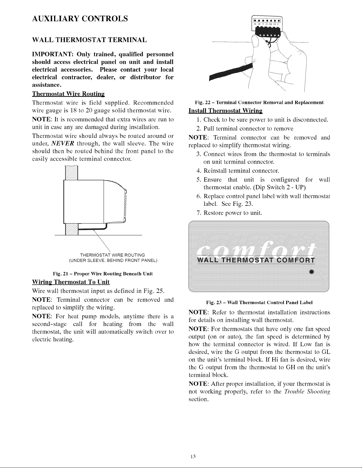
Fig.
22
—
Terminal
Connector
Removal
and
Replacement
Install
Thermostat
Wiring
1.
Check
to
be
sure
power
to
unit
is
disconnected.
2.
Pull
terminal
connector
to
remove
NOTE:
Terminal
connector
can
be
removed
and
replaced
to
simplify
thermostat
wiring.
3.
Connect
wires
from
the
thermostat
to
terminals
on
unit
terminal
connector.
4.
Reinstall
terminal
connector.
5.
Ensure
that
unit
is
configured
for
wall
thermostat
enable.
(Dip
Switch
2
-
UP)
6.
Replace
control
panel
label
with
wall
thermostat
label.
See
Fig.
23.
7.
Restore
power
to
unit.
WALL
THERMOSTAT
COMFORT
©
Fig.
23
—
Wall
Thermostat
Control
Panel
Label
NOTE:
Refer
to
thermostat
installation
instructions
for
details
on
installing
wall
thermostat.
NOTE:
For
thermostats
that
have
only
one
fan
speed
output
(on
or
auto),
the
fan
speed
is
determined
by
how
the
terminal
connector
is
wired.
If
Low
fan
is
desired,
wire
the
G
output
from
the
thermostat
to
GL
on
the
unit’s
terminal
block.
If
Hi
fan
is
desired,
wire
the
G
output
from
the
thermostat
to
GH
on
the
unit’s
terminal
block.
NOTE:
After
proper
installation,
if
your
thermostat
is
not
working
properly,
refer
to
the
Trouble
Shooting
section.
13
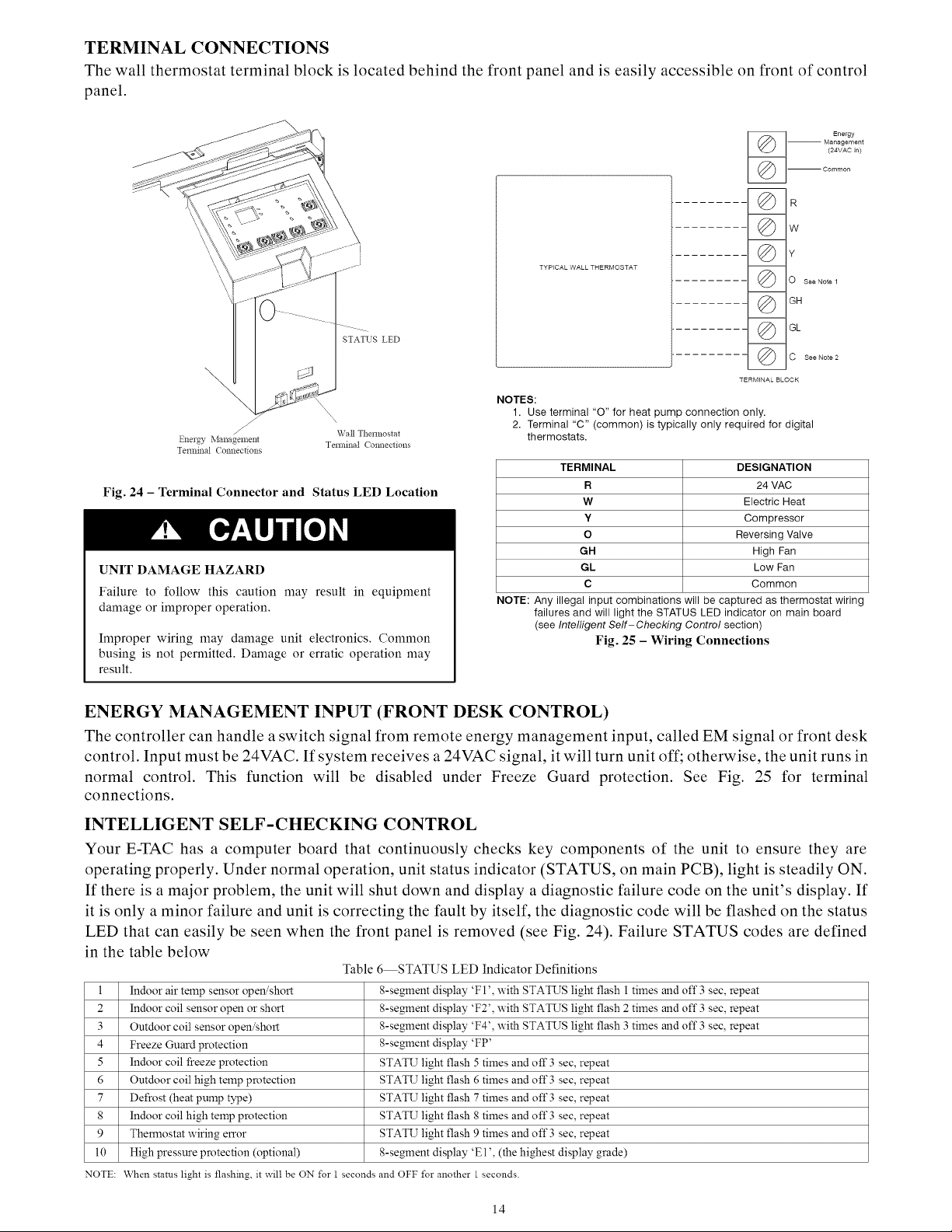
TERMINAL
CONNECTIONS
The
wall
thermostat
terminal
block
is
located
behind
the
front
panel
and
is
easily
accessible
on front
of
control
panel.
STATUS
LED
TYPICAL
WALL
THERMOSTAT
NOTES:
@
@
@
@
a
D
\y
@
@
@
@
Energy
Management
(24VAC
in}
Common
R
WwW
O
see
Note
4
GH
GL
C
See
Note
2
TERMINAL
BLOCK
1.
Use
terminal
“O”
for
heat
pump
connection
only.
2.
Terminal
“C”
(common)
is
typically
only
required
for
digital
Wall
Thermostat
Energy
Management
Terminal
Connections
thermostats.
Terminal
Connections
TERMINAL
DESIGNATION
Fig.
24
—
Terminal
Connector
and
Status
LED
Location
R
24
VAC
WwW
Electric
Heat
Y
Compressor
oO
Reversing
Valve
GH
High
Fan
UNIT
DAMAGE
HAZARD
GL Low
Fan
c
Common
Failure
to
follow
this
caution
may
result
in
equipment
damage
or
improper
operation.
NOTE:
Any
illegal
input
combinations
will
be
captured
as
thermostat
wiring
failures
and
will
light
the
STATUS
LED
indicator
on
main
board
(see
Intelligent
Self-Checking
Contro/
section)
Improper
wiring
may
damage
unit
electronics.
Common
Fig.
25
—
Wiring
Connections
busing
is
not
permitted.
Damage
or
erratic
operation
may
result.
ENERGY
MANAGEMENT
INPUT
(FRONT
DESK
CONTROL)
The
controller
can
handle
a
switch
signal
from
remote
energy
management
input,
called
EM
signal
or
front
desk
control.
Input
must
be
24VAC.
If
system
receives
a
24VAC
signal,
it
will
turn
unit
off;
otherwise,
the
unit
runs
in
normal
control.
This
function
will be
disabled
under
Freeze
Guard
protection.
See
Fig.
25
for
terminal
connections.
INTELLIGENT
SELF-CHECKING
CONTROL
Your
E-TAC
has
a
computer
board
that
continuously
checks
key
components
of
the
unit
to
ensure
they
are
operating
properly.
Under
normal
operation,
unit
status
indicator
(STATUS,
on
main
PCB),
light
is
steadily
ON.
If
there
is
a
major
problem,
the
unit will
shut
down
and
display
a
diagnostic
failure
code
on
the
unit’s
display.
If
it
is
only
a
minor
failure
and
unit
is
correcting
the
fault
by
itself,
the
diagnostic
code
will
be
flashed
on
the
status
LED
that
can
easily
be
seen
when
the
front
panel
is
removed
(see
Fig. 24),
Failure
STATUS
codes
are
defined
in
the
table
below
Table
6—STATUS
LED
Indicator
Definitions
I
Indoor
air
temp
sensor
open/short
8-segment
display
‘Fl’,
with
STATUS
light
flash
|
times and
off
3
sec,
repeat
2
Indoor
coil
sensor
open
or
short
8-segment
display
‘F2’,
with
STATUS
light
flash
2
times and
off
3
sec,
repeat
3
Outdoor
coil
sensor
open/short
8-segment
display
‘F4’,
with
STATUS
light
flash
3
times and
off
3
sec,
repeat
4
Freeze
Guard
protection
8-segment
display
‘FP’
5
Indoor
coil
freeze
protection
STATU
light
flash
5
times and
off
3
sec,
repeat
6
Outdoor
coil
high
temp
protection
STATU
light
flash
6
times and
off
3
sec,
repeat
7
Defrost
(heat
pump
type)
STATU
light
flash
7
times and
off
3
sec,
repeat
8
Indoor
coil
high
temp
protection
STATU
light
flash
8
times and
off
3
sec,
repeat
9
Thermostat
wiring
error
STATU
light
flash
9
times and
off
3
sec,
repeat
10
High
pressure protection
(optional)
8-segment
display
‘El’,
(the
highest
display
grade)
NOTE:
When
status
light
is
flashing,
it
will
be
ON
for
1
seconds
and
OFF
for
another
|
seconds.
14
OPERATION
IMPORTANT:
When
unit
is
first
started,
high
humidity
conditions
can
cause
condensation
to
form
on
discharge
grille.
Keep
doors and
windows
closed.
Room
humidity
will
decrease
and
moisture
will
evaporate.
sel
[EVP
@
INDOOR
@
SEIPOIN]
WARMER
TEMP
CONTROL
COOLER
FAN,
MODE&
OPERATION
©
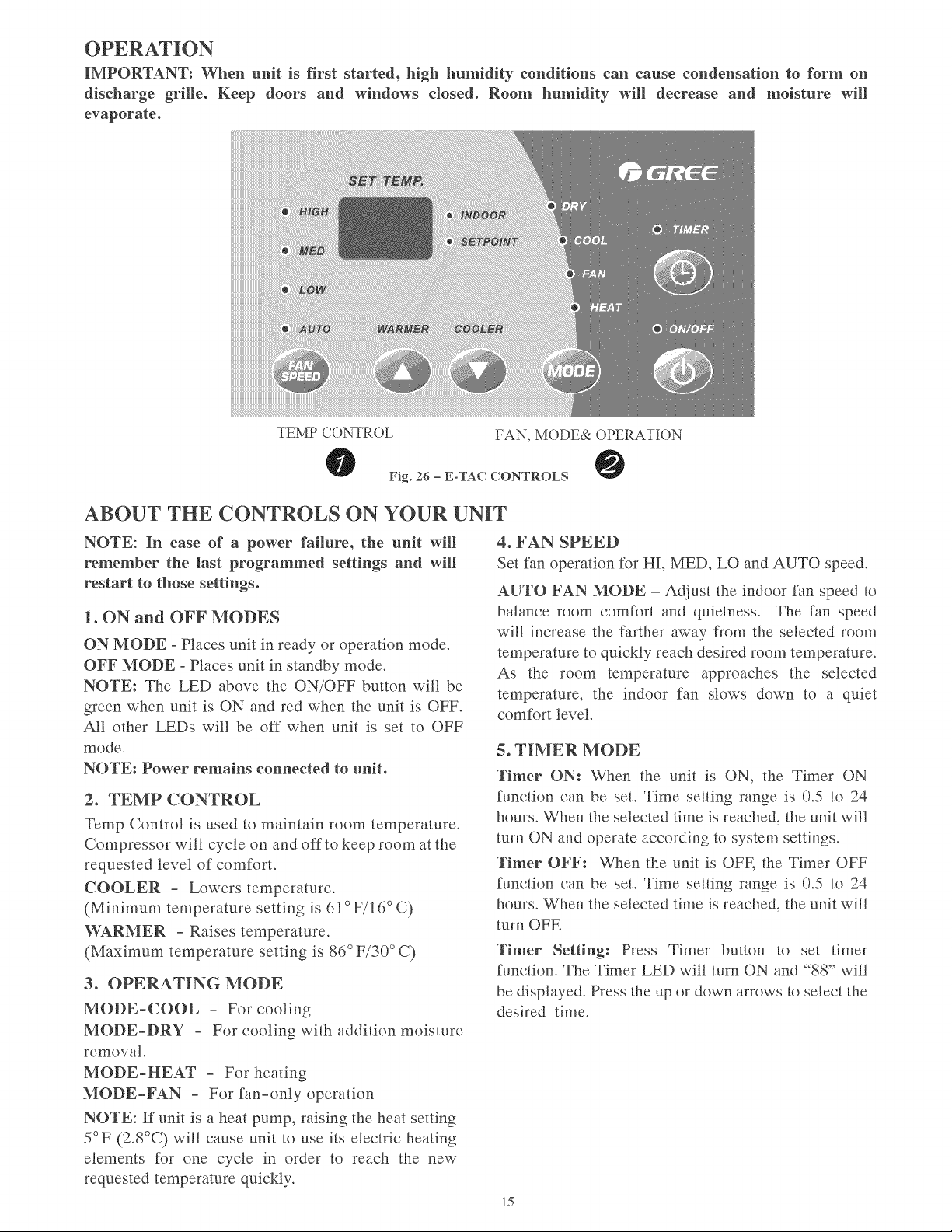
Fig. 26
-
E-TAC
CONTROLS
@
ABOUT
THE
CONTROLS
ON
YOUR
UNIT
NOTE:
In
case
of
a
power
failure,
the
unit
will
remember
the
last
programmed
settings
and
will
restart
to
those
settings.
1.
ON
and
OFF
MODES
ON
MODE
-
Places
unit
in
ready
or
operation
mode.
OFF
MODE
-
Places
unit
in
standby
mode.
NOTE:
The
LED
above
the
ON/OFF
button
will be
green
when
unit
is
ON
and
red
when
the
unit
is
OFF.
All
other
LEDs
will be
off
when
unit
is
set
to
OFF
mode.
NOTE:
Power
remains
connected
to
unit.
2.
TEMP
CONTROL
Temp
Control
is
used
to
maintain
room
temperature.
Compressor
will
cycle
on
and
off
to
keep
room
at
the
requested
level
of
comfort.
COOLER
-
Lowers
temperature.
(Minimum
temperature
setting
is
61°
F/16°
C)
WARMER
-
Raises
temperature.
(Maximum
temperature
setting
is
86°
F/30°
C)
3.
OPERATING
MODE
MODE-COOL
-
For
cooling
MODE-DRY
-
For
cooling
with
addition
moisture
removal.
MODE-HEAT
-
For
heating
MODE-FAN
-
For
fan-only
operation
NOTE:
If
unit
is
a
heat
pump,
raising
the
heat
setting
5°F
(2.8°C)
will
cause
unit
to
use
its
electric
heating
elements
for
one
cycle
in
order
to
reach
the
new
requested
temperature
quickly.
4.
FAN
SPEED
Set fan
operation
for
HI,
MED,
LO
and
AUTO
speed.
AUTO
FAN
MODE
—
Adjust
the
indoor
fan
speed
to
balance
room
comfort
and
quietness.
The
fan
speed
will
increase
the
farther
away
from
the
selected
room
temperature
to
quickly
reach
desired
room
temperature.
As
the
room
temperature
approaches
the
selected
temperature,
the
indoor
fan
slows
down
to
a
quiet
comfort
level.
5.
TIMER
MODE
Timer
ON:
When
the
unit
is
ON,
the
Timer
ON
function
can
be
set.
Time
setting
range
is
0.5
to
24
hours.
When
the
selected
time
is
reached,
the
unit will
turn
ON
and
operate
according
to
system
settings.
Timer
OFF:
When
the
unit
is
OFF,
the
Timer
OFF
function
can
be
set.
Time
setting
range
is
0.5
to
24
hours.
When
the
selected
time
is
reached,
the
unit will
turn
OFF.
Timer
Setting:
Press
Timer
button
to
set
timer
function.
The
Timer
LED
will
turn
ON
and
“88”
will
be
displayed.
Press
the
up
or
down
arrows
to
select
the
desired
time.
15
CARE
AND
CLEANING
FRONT
PANEL
AND
CASE
Turn
unit
off
and
disconnect
power
supply.
To
clean,
use
water
and
a
mild
detergent.
DO
NOT
use
bleach
or
abrasives.
Some
commercial
cleaners
may
damage
the
plastic
parts.
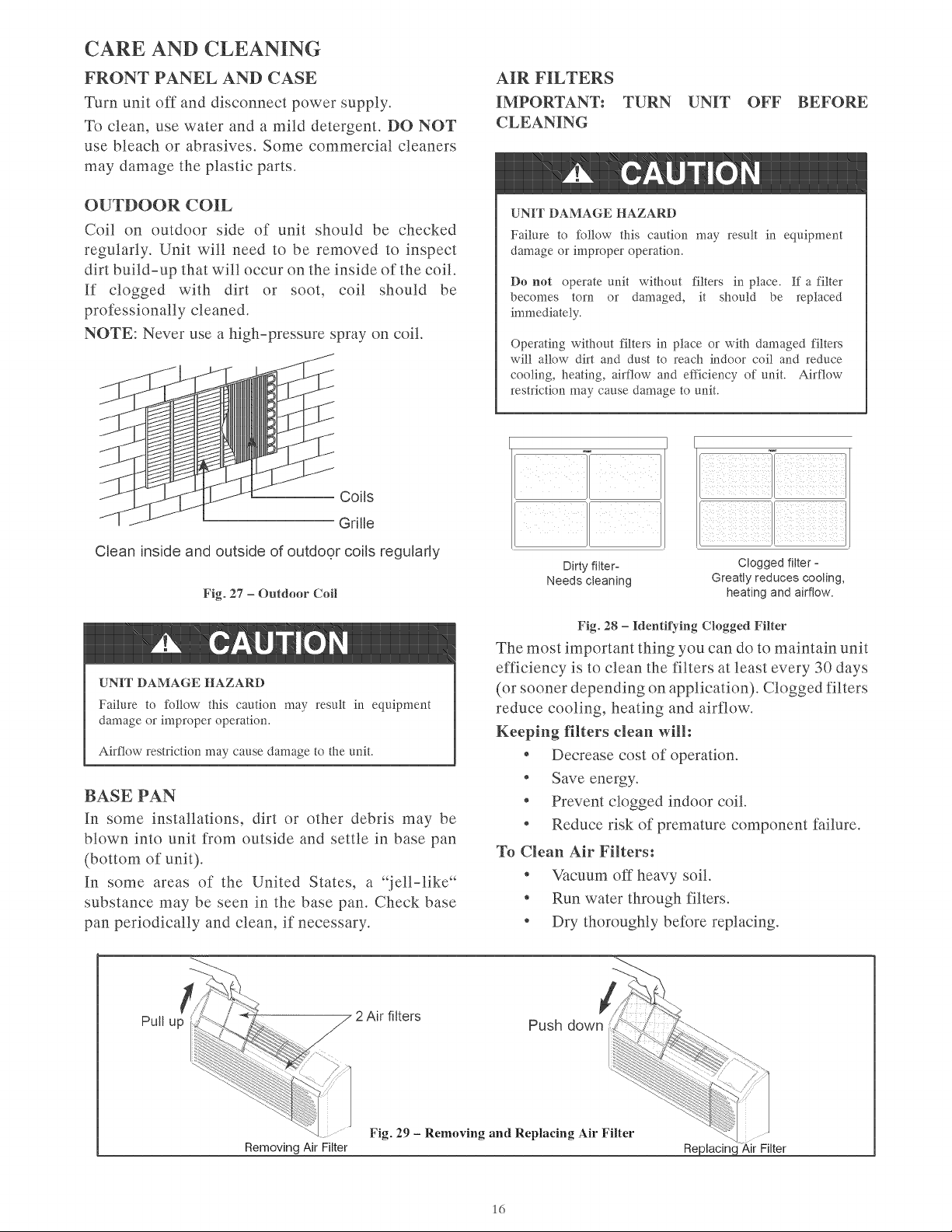
OUTDOOR
COIL
Coil
on
outdoor
side
of
unit
should
be
checked
regularly.
Unit
will
need
to
be
removed
to
inspect
dirt
build-up
that
will
occur
on
the
inside
of
the
coil.
If
clogged
with
dirt
or
soot,
coil
should
be
professionally
cleaned.
NOTE:
Never
use
a
high-pressure
spray
on
coil.
TM,
+
NN
hy
A
Hi
ANN
|
Coils
Grille
Clean
inside
and
outside
of
outdoor
coils
regularly
Fig.
27
—
Outdoor
Coil
4
CAUTION
UNIT
DAMAGE
HAZARD
Failure
to
follow
this
caution
may
result
in
equipment
damage
or
improper
operation.
Airflow
restriction
may
cause
damage
to
the
unit.
BASE
PAN
In
some
installations,
dirt
or
other
debris
may
be
blown
into
unit
from
outside
and
settle
in
base
pan
(bottom
of
unit).
In
some
areas
of
the
United
States,
a
“jell-like*
substance
may
be
seen
in
the
base
pan.
Check
base
pan
periodically
and
clean,
if
necessary.
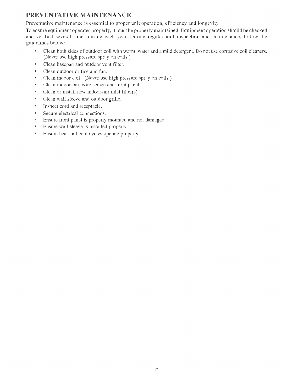
AIR
FILTERS
IMPORTANT:
TURN
UNIT
OFF
BEFORE
CLEANING
4
CAUTION
UNIT
DAMAGE
HAZARD
Failure
to
follow
this
caution
may
result
in
equipment
damage
or
improper
operation.
Do
not
operate
unit
without
filters
in
place.
If
a
filter
becomes
torn
or
damaged,
it
should
be
replaced
immediately.
Operating
without
filters
in
place
or
with
damaged
filters
will
allow
dirt
and
dust
to
reach
indoor
coil
and
reduce
cooling,
heating,
airflow
and
efficiency
of
unit.
Airflow
restriction
may
cause
damage
to
unit.
ae
Lf]
|
Dirty
filter-
Clogged
filter
-
Needs
cleaning
Greatly
reduces
cooling,
heating and
airflow.
Fig.
28
—
Identifying
Clogged
Filter
The
most
important
thing
you
can
do
to
maintain
unit
efficiency
is
to
clean
the
filters
at
least
every
30
days
(or
sooner
depending
on
application).
Clogged
filters
reduce
cooling,
heating
and
airflow.
Keeping
filters
clean
will:
*
Decrease
cost
of
operation.
*
Save
energy.
«
Prevent
clogged
indoor
coil.
*
Reduce
risk
of
premature
component
failure.
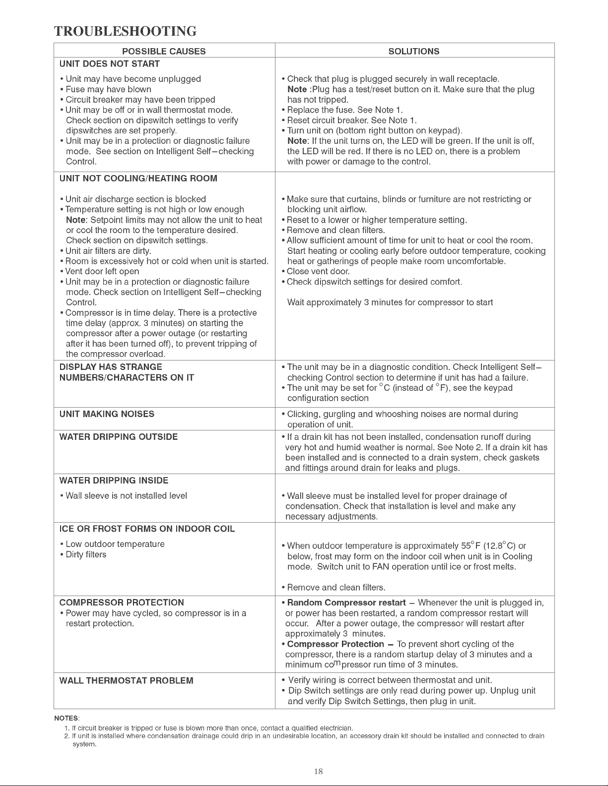
To
Clean
Air
Filters:
*
Vacuum
off
heavy
soil.
*
Run
water
through
filters.
¢
Dry
thoroughly
before
replacing.
2
Air
filters
Removing
Air
Filter
Fig.
29
-
Removing
and
Replacing
Air
Filter
Replacing
Air
Filter
16
PREVENTATIVE
MAINTENANCE
Preventative
maintenance
is
essential
to
proper
unit
operation,
efficiency
and
longevity.
To
ensure
equipment
operates
properly,
it
must
be
properly
maintained.
Equipment
operation
should
be
checked
and
verified
several
times
during
each
year.
During
regular
unit
inspection
and
maintenance,
follow
the
guidelines
below:
*
Clean
both
sides
of
outdoor
coil
with
warm
water
and
a
mild
detergent.
Do
not
use
corrosive
coil
cleaners.
(Never
use
high
pressure
spray
on
coils.)
*
Clean
basepan
and
outdoor
vent
filter.
*
Clean
outdoor
orifice
and
fan.
*
Clean
indoor
coil.
(Never
use
high
pressure
spray
on
coils.)
*
Clean
indoor
fan,
wire screen
and
front
panel.
*
Clean
or
install
new
indoor-air
inlet
filter(s).
*
Clean
wall
sleeve
and
outdoor
grille.
*
Inspect
cord
and
receptacle.
*
Secure
electrical
connections.
¢
Ensure
front
panel
is
properly
mounted
and
not
damaged.
*
Ensure
wall
sleeve
is
installed
properly.
*
Ensure
heat
and
cool
cycles
operate
properly.
17
TROUBLESHOOTING
POSSIBLE
CAUSES
SOLUTIONS
UNIT
DOES
NOT
START
e
Unit
may
have
become
unplugged
e
Fuse
may
have
blown
e
Circuit
breaker
may
have
been
tripped
e
Unit
may
be
off
or
in
wall
thermostat
mode.
Check
section
on
dipswitch
settings
to
verify
dipswitches
are
set
properly.
e
Unit
may
be
in
a
protection
or
diagnostic
failure
mode.
See
section
on
Intelligent
Self—checking
Control.
e
Check
that
plug
is
plugged
securely
in
wall
receptacle.
Note
:Plug
has
a
test/reset
button
on
it.
Make
sure
that
the
plug
nas
not
tripped.
*
Replace
the
fuse.
See
Note
1.
*
Reset
circuit
breaker.
See
Note
1.
e
Turn
unit
on
(bottom
right
button
on
keypad).
Note:
If
the
unit
turns
on,
the
LED
will
be
green.
If
the
unit
is
off,
the
LED
will
be
red.
If
there
is
no
LED
on,
there
is
a
problem
with
power
or
damage
to
the
control.
UNIT
NOT
COOLING/HEATING
ROOM
e
Unit
air
discharge
section
is
blocked
e
Temperature
setting
is
not
high
or
low
enough
Note:
Setpoint
limits
may
not
allow
the
unit
to
heat
or
cool
the
room
to
the
temperature
desired.
Check
section
on
dipswitch
settings.
e
Unit
air
filters
are
dirty.
e
Room
is
excessively
hot
or
cold
when
unit
is
started.
e
Vent
door
left
open
e
Unit
may
be
in
a
protection
or
diagnostic
failure
mode.
Check
section
on
Intelligent
Self—checking
Control.
«
Compressor
is
in
time
delay.
There
is
a
protective
time
delay
(approx.
3
minutes)
on
starting
the
compressor
after
a
power
outage
(or
restarting
after
it
has
been
turned
off),
to
prevent
tripping
of
the
compressor
overload.
e
Make
sure
that
curtains,
blinds
or
furniture
are
not
restricting
or
blocking
unit
airflow.
e
Reset
to
a
lower
or
higher
temperature
setting.
e
Remove
and
clean
filters.
e
Allow
sufficient
amount
of
time
for
unit
to
heat
or
cool
the
room.
Start
heating
or
cooling
early
before
outdoor
temperature,
cooking
neat
or
gatherings
of
people
make
room
uncomfortable.
«
Close
vent
door.
e
Check
dipswitch
settings
for
desired
comfort.
Wait
approximately
3
minutes
for
compressor
to
start
DISPLAY
HAS
STRANGE
NUMBERS/CHARACTERS
ON
IT
e
The
unit
may
be
in
a
diagnostic
condition.
Check
Intelligent
Self—
checking
Control
section
to
determine
if
unit
has
had
a
failure.
*
The
unit
may
be
set
for
°C
(instead
of
°F),
see
the
keypad
configuration
section
UNIT
MAKING
NOISES
e
Clicking,
gurgling
and
whooshing
noises
are
normal
during
operation
of
unit.
WATER
DRIPPING
OUTSIDE
e
if
a
drain
kit
has
not
been
installed,
condensation
runoff
during
very
hot
and
humid
weather
is
normal.
See
Note
2.
If
a
drain
kit
has
been
installed
and
is
connected
to
a
drain
system,
check
gaskets
and
fittings
around
drain
for
leaks
and
plugs.
WATER
DRIPPING
INSIDE
e
Wall
sleeve
is
not
installed
level
*
Wall
sleeve
must
be
installed
level
for
proper
drainage
of
condensation.
Check
that
installation
is
level
and
make
any
necessary
adjustments.
ICE
OR
FROST
FORMS
ON
INDOOR
COIL
*
Low
outdoor
temperature
e
Dirty
filters
*
When
outdoor
temperature
is
approximately
55°F
(12.8°C)
or
below,
frost
may
form
on
the
indoor
coil
when
unit
is
in
Cooling
mode.
Switch
unit
to
FAN
operation
until
ice
or
frost
melts.
e
Remove
and
ciean
filters.
COMPRESSOR
PROTECTION
*
Power may
have
cycled,
so
compressor
is
ina
restart
protection.
e
Random
Compressor
restart
—
Whenever
the
unit
is
plugged
in,
or
power
has
been
restarted,
a
random
compressor
restart
will
occur.
After
a
power
outage,
the
compressor
will
restart
after
approximately
3
minutes.
«
Compressor
Protection
—
To
prevent
short
cycling
of
the
compressor,
there
is
a
random
startup
delay
of
3
minutes
and
a
minimum
co™
pressor
run
time
of
3
minutes.
WALL
THERMOSTAT
PROBLEM
e
Verify
wiring
is
correct
between
thermostat
and
unit.
e
Dip
Switch
settings
are
only
read
during
power
up.
Unplug
unit
and
verify
Dip
Switch
Settings,
then
plug
in
unit.
NOTES:
1.
If
circuit
breaker
is
tripped
or
fuse
is
blown
more
than
once,
contact
a
qualified
electrician.
2.
If
unit
is
installed
where
condensation
drainage
could
drip
in
an
undesirable
location,
an
accessory
drain
kit
should
be
installed
and
connected
to
drain
system.
18
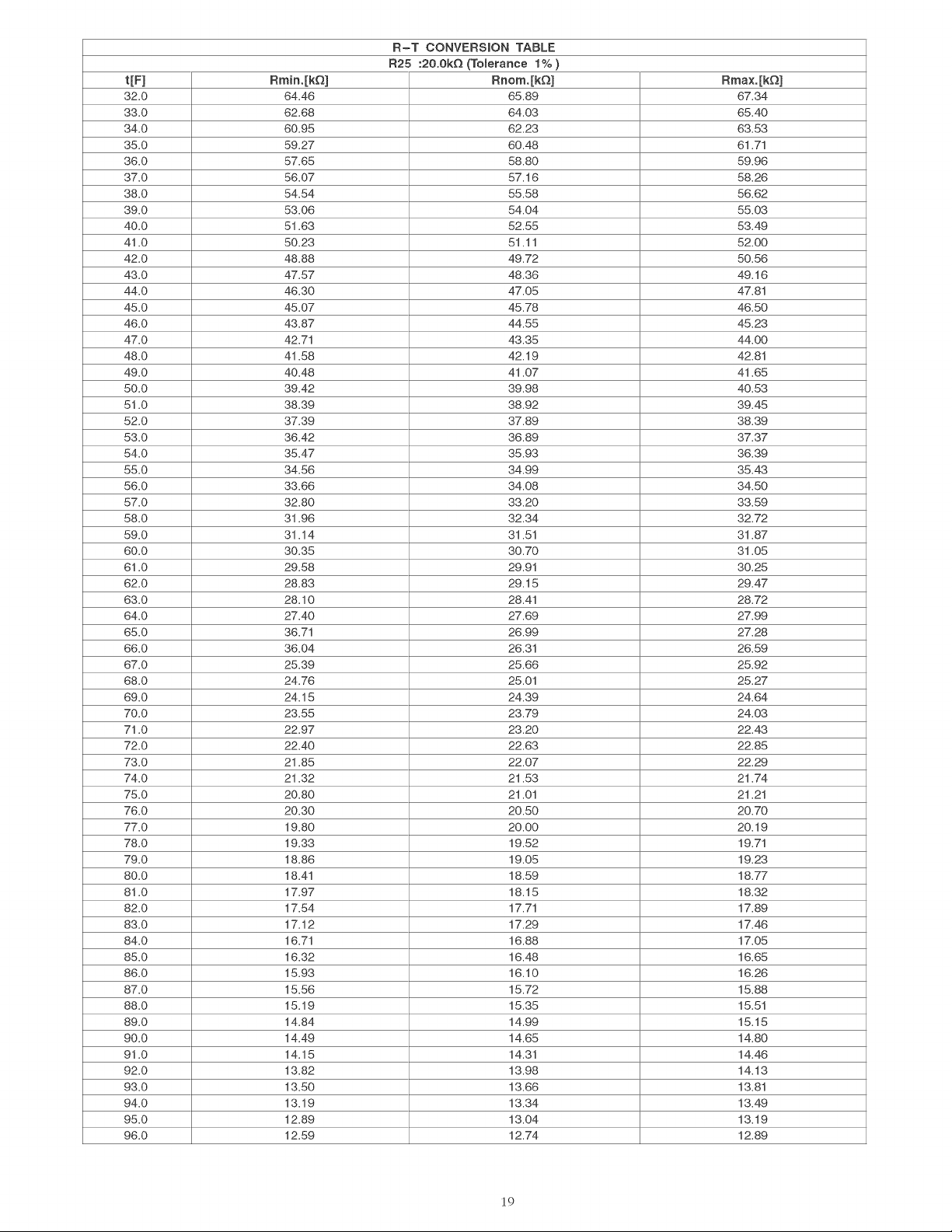
R-T
CONVERSION
TABLE
R25 :20.0kQ
(Tolerance
1%
)
t[F]
Rmin.[kQ]
Rnom.[kQ]
Rmax.[kQ]
32.0
64.46
65.89
87.34
33.0
62.68 64.03
65.40
34.0
60.95
62.23 63.53
35.0
59.27 60.48
61.71
36.0
57.65
58.80
59.96
37.0
56.07
57.16 58.26
38.0
54.54 55.58 56.62
39.0
53.06
54.04
55.03
40.0
51.63 52.55 53.49
41.0
50.23
51.11
52.00
42.0
48.88 49.72 50.56
43.0
47
87
48.36 49.16
44.0
46.30
47.05
47
81
45.0
45.07 45.78 46.50
46.0
43.87 44.55 45.23
47.0
42,71
43.35 44.00
48.0
41.58 42.19
42.81
49.0
40.48 41.07 41.65
50.0
39.42
39.98
40.53
51.0
38.39
38.92
39.45
52.0
37.39 37.89 38.39
53.0
36.42 36.89 37.37
54.0
35.47
35.93
36.39
55.0
34.56
34.99
35.43
56.0
33.66
34.08
34.50
57.0
32.80
33.20 33.59
58.0
31.96 32.34 32.72
59.0
31.14
31.51
31.87
60.0
30.35
30.70 31.05
61.0
29.58
29.91
30.25
62.0
28.83
29.15
29.47
63.0
28.10
28.41
28.72
64.0
27.40
27.69 27.99
65.0
36.71
26.99
27.28
66.0
36.04
26.31
26.59
67.0
25.39 25.66 25.92
68.0
24.76
25.01
25.27
69.0
24.15 24.39 24.64
70.0
23.55 23.79 24.03
71.0
22.97
23.20 22.43
72.0
22.40
22.63 22.85
73.0
21.85
22.07
22.29
74.0
21.32 21.53 21.74
75.0
20.80
21.01 21.21
76.0
20.30 20.50 20.70
77.0
19.80
20.00
20.19
78.0
19.33 19.52
19.71
79.0
18.86 19.05 19.23
80.0
18.44
18.59 18.77
81.0
17.97 18.15 18.32
82.0
17.54
17.71
17.89
83.0
17.12 17.29 17.46
84.0
16.71
16.88 17.05
85.0
16.32 16.48 16.65
86.0
15.93 16.10 16.26
87.0
15.56 15.72 15.88
88.0
15.19 15.35
15.51
89.0
14.84 14.99 15.15
90.0
14.49 14.65 14.80
91.0
14.15
14.31
14.46
92.0
13.82 13.98 14.13
93.0
13.50 13.66
13.81
94.0
13.19 13.34 13.49
95.0
12.89 13.04 13.19
96.0
12.59 12.74 12.89
19
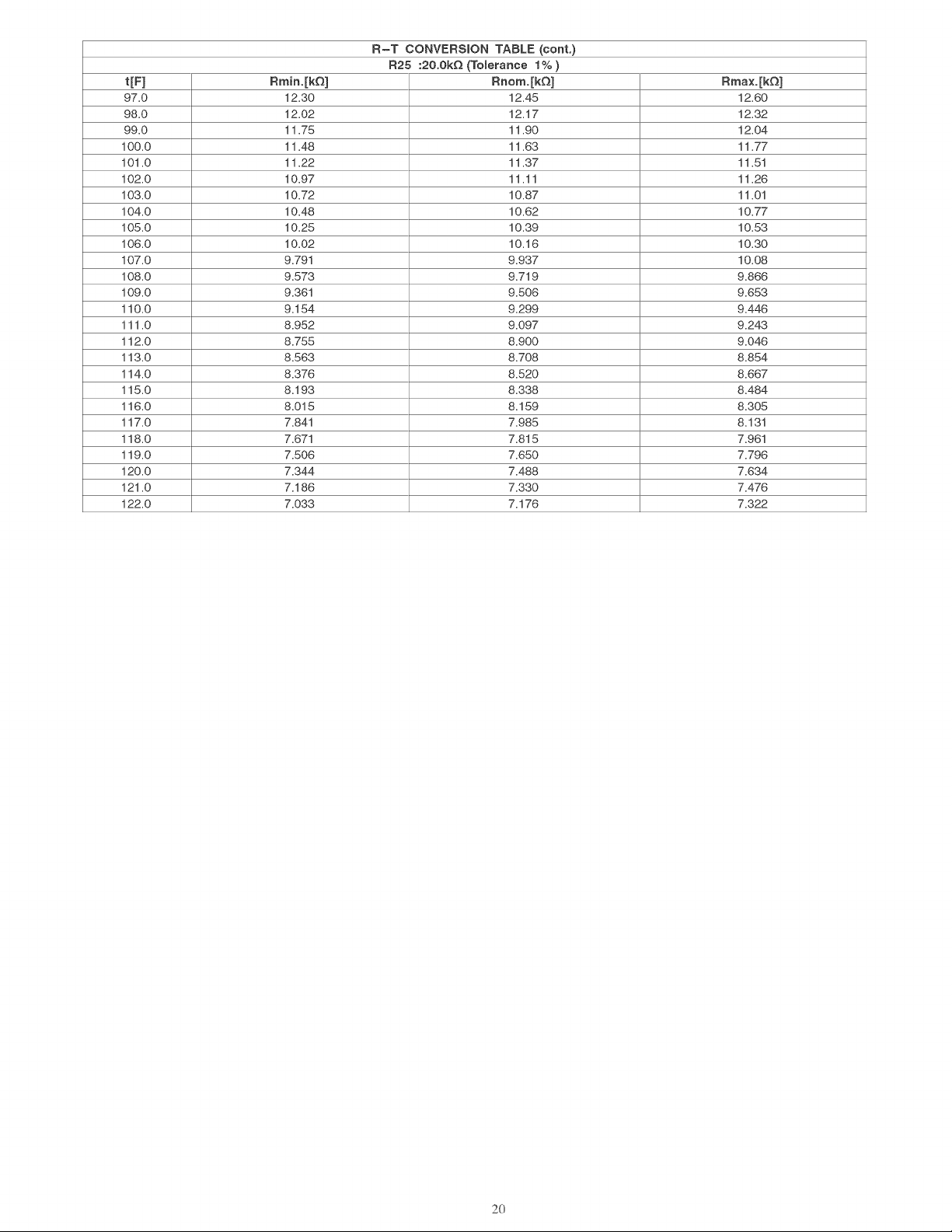
R-T
CONVERSION
TABLE
(cont.
R25 :20.0kQ
(Tolerance
1%
)
t[F]
Rmin.[kQ]
Rnom.[kQ]
Rmax.[kQ]
97.0
12.30 12.45 12.60
98.0
12.02 12.17 12.32
99.0
11.75 11.90 12.04
100.0 11.48 11.63 11.77
101.0 11.22
11.37
11.51
102.0 10.97
11.14
11.26
103.0 10.72 10.87
11.01
104.0 10.48 10.62 10.77
105.0 10.25 10.39 10.53
106.0 10.02 10.16 10.30
107.0
9.791
9.937
10.08
108.0
9.573 9.719 9.866
109.0
9.361
9.506 9.653
110.0
9.154 9.299 9.446
111.0
8.952 9.097 9.243
112.0
8.755 8.900 9.046
113.0
8.563 8.708 8.854
114.0
8.376 8.520 8.667
115.0
8.193 8.338 8.484
116.0
8.015 8.159 8.305
117.0
7.841
7.985
8.131
118.0
7.671
7.815
7.961
119.0
7.506 7.650 7.796
120.0
7.344
7
A88
7.634
121.0
7.186 7.330
7
ATE
122.0
7.033
7.4176
7.322
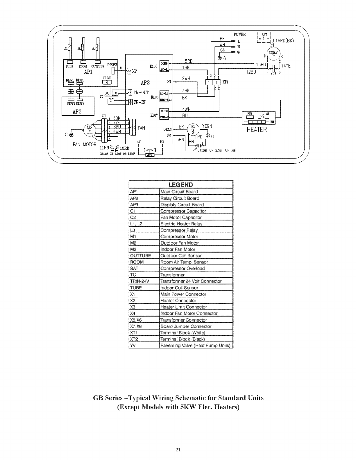
—i
L
BK
2 2
@
on
N
¢
®
co
G
RREAS
mI
19RD
mee
rood
ovrrupe
DISES)
KL05
on
1BK
13BU
LJ
ve
APL
xv
]
12801
Oya
PUMP
2WH
So
=)
AP2
x
xn
G3
&
TR-OUT
“a
|_
38K
J
Eero
|
i
BK
DISPL
DIP?
C=
TR-IN
=
AP3
1_6BK__
bs
5_/YE
is
2_BBU
3
OWH
4
6
FAN
MOTOR
1ABN
44
24
10RD
SN
C21uF
OR
L2uF
OR
1.5uP
Lee
|
S
LEGEND
Main
Circuit
Board
Ci
G2
Fan
Mator
Li,
Le
Electric
Heater
Mi
Motor
M2
Quidoor
Fan
Motor
Ma
QUTTUBE
Gail
Sensor
Aur
SAT
Overload
iis
Transformer
TRIN-24
24
TUBE
Coil
Sensor
Main
Power
Connector
x
xe
xo
Heater
Limit
aA
x?
Board
Connector
AY
xT2
Terminal
Block
vi
Valve
GB
Series
—Typical
Wiring
Schematic
for
Standard
Units
(Except
Models
with
5K
W
Elec.
Heaters)
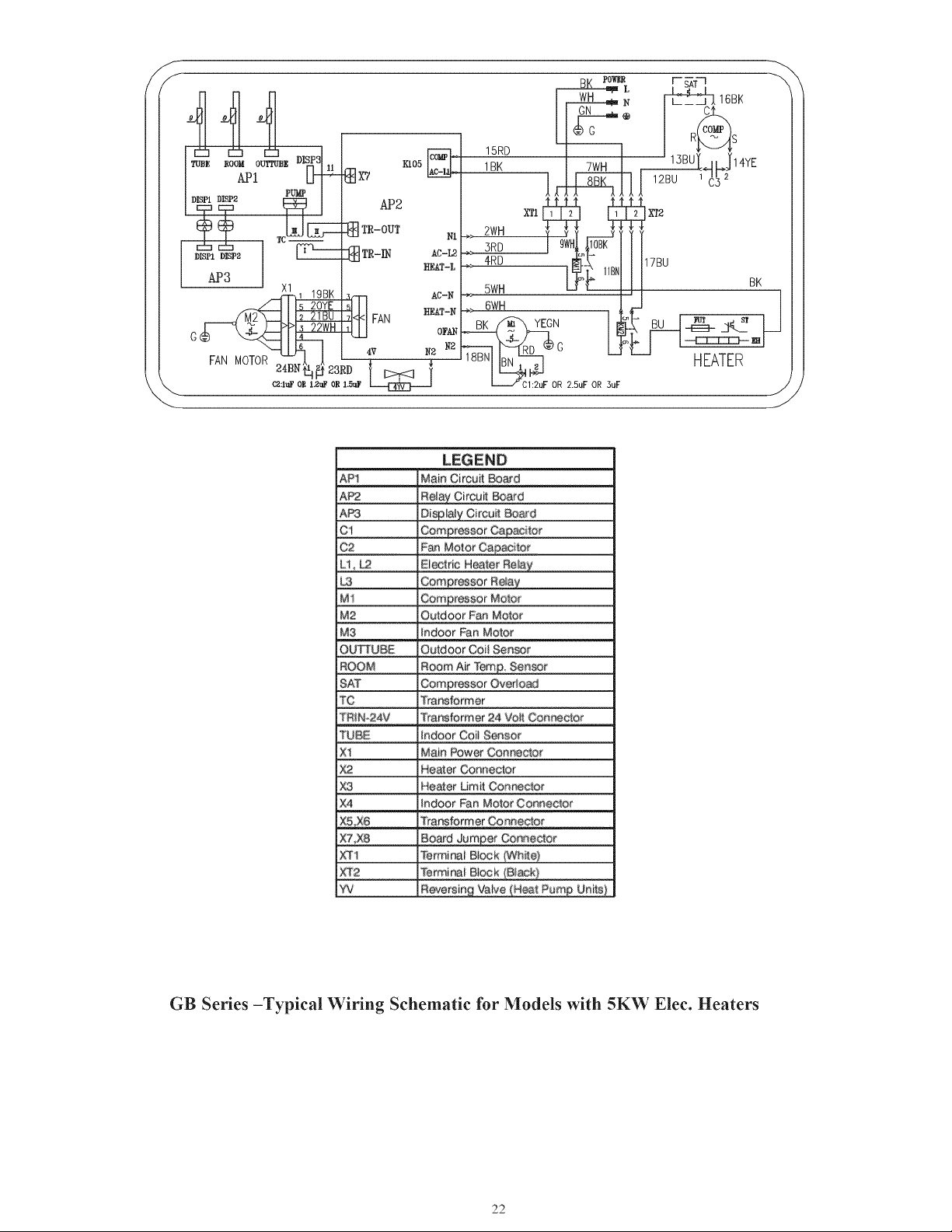
co
co
fo
15RD
ruse
rood
ourrupg
DISPS)
|
xis
[OM 1BK
TWH
13BU
ofp
NE
a
ACH
API
gx?
8
C
DISPL
DISP2
FUME
0
GO
3s
(zt
mr-our
ia
here
ng
TR-IN
APS
\
tf
|
(218
)
PP
_22WH
6é
fo
AN
MOTOR
F
24BN
41,
Ef
23RD
‘
NS
Ca:luF
OR
L.2uF
OR
1.5uF
ER,
z
=
LEGEND
API
Main
Circuit
Board
AP2
Relay
Circuit
Board
APS
Displaly
Circuit
Board
Ci
Compressor
Capacitor
C2
Fan
Motor
Capacitor
Li,
Le
Electric
Heater
Relay
LS
Compressor
Relay
Mi
Compressor
Motor
Me
Outdoor
Fan
Motor
Mo
indoor
Fan
Motor
OUTTUBE
Outdoor
Coil
Sensor
ROOM
Roorn
Air
Tern.
Sensor
SAT
Compressor
Overload
Te
Transformer
TRIN-24V
Transformer
24
Volt
Connector
TUBE
indoor
Coil
Sensor
Al
Main
Power
Connector
Ke
Heater
Connector
XS
Heater
Limit
Connector
x4
Indoor
Fan
Motor
Connector
ABE
Transtormer
Connector
x7,
X8
Board
Jumper
Gonmector
XT4
Terminal
Block
(White)
xT2
Terminal
Block
(Black)
¥V
Reversing
Valve
(Heat
Purng
Units)
GB
Series
—Typical
Wiring
Schematic
for
Models
with
5K'W
Elec.
Heaters
No
No
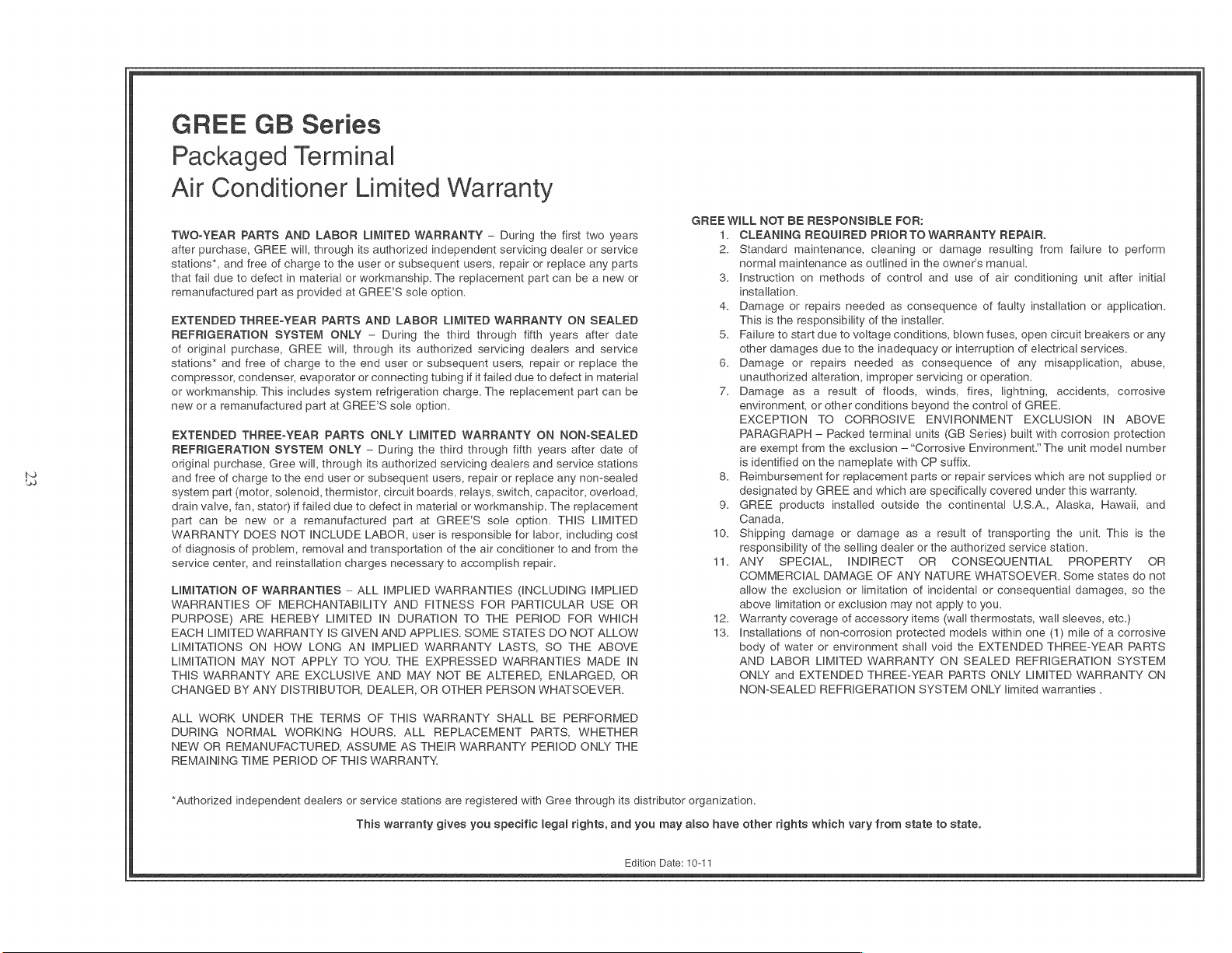
GREE
GB
Series
Packaged
Terminal
Air
Conditioner
Limited
Warranty
TWO-YEAR
PARTS AND
LABOR
LIMITED
WARRANTY
—
During
the
first
two
years
after
purchase,
GREE
will,
through
its
authorized
independent
servicing
dealer
or
service
stations”,
and
free
of
charge
to
the
user
or
subsequent
users,
repair
or
replace
any
parts
that
fail
due
to
defect
in
material
or
workmanship.
The
replacement
part
can
be
a
new
or
remanufactured
part
as
provided
at
GREE’S
sole
option.
EXTENDED
THREE-YEAR
PARTS
AND
LABOR
LIMITED
WARRANTY
ON
SEALED
REFRIGERATION
SYSTEM
ONLY
—
During
the
third
through
fifth
years
after
date
of
original
purchase,
GREE
will,
through
its
authorized
servicing
dealers
and
service
stations”
and
free
of
charge
to
the
end
user
or
subsequent
users,
repair
or
replace
the
compressor,
condenser,
evaporator
or
connecting
tubing
if it
failed
due
to
defect
in
material
or
workmanship.
This
includes
system
refrigeration
charge.
The
replacement
part
can
be
new
or
a
remanufactured
part
at
GREE’S
sole
option.
EXTENDED
THREE-YEAR
PARTS
ONLY
LIMITED
WARRANTY
ON
NON-SEALED
REFRIGERATION
SYSTEM
ONLY
—
During
the
third
through
fifth
years
after
date
of
original
purchase,
Gree
will,
through
its
authorized
servicing
dealers
and
service
stations
and
free
of
charge
to
the
end
user
or
subsequent
users,
repair
or
replace
any
non-sealed
system
part
(motor,
solenoid,
thermistor,
circuit
boards,
relays,
switch,
capacitor,
overload,
drain
valve,
fan,
stator)
if
failed
due
to
defect
in
material
or
workmanship.
The
replacement
part
can
be
new
or
a
remanufactured
part
at
GREE’S
sole
option.
THIS
LIMITED
WARRANTY
DOES
NOT
INCLUDE
LABOR,
user
is
responsible
for
labor,
including
cost
of
diagnosis
of
problem,
removal
and
transportation
of
the
air
conditioner
to
and
from
the
service
center,
and
reinstallation
charges
necessary
to
accomplish
repair.
LIMITATION
OF
WARRANTIES
—
ALL
IMPLIED
WARRANTIES
(INCLUDING
IMPLIED
WARRANTIES
OF
MERCHANTABILITY
AND FITNESS
FOR
PARTICULAR
USE
OR
PURPOSE)
ARE
HEREBY
LIMITED
IN
DURATION
TO
THE
PERIOD
FOR
WHICH
EACH
LIMITED
WARRANTY
IS
GIVEN
AND
APPLIES.
SOME
STATES
DO
NOT
ALLOW
LIMITATIONS
ON
HOW
LONG
AN
IMPLIED
WARRANTY
LASTS,
SO
THE
ABOVE
LIMITATION
MAY
NOT
APPLY
TO
YOU.
THE
EXPRESSED
WARRANTIES
MADE
IN
THIS
WARRANTY
ARE
EXCLUSIVE
AND
MAY NOT
BE
ALTERED,
ENLARGED,
OR
CHANGED
BY
ANY
DISTRIBUTOR,
DEALER,
OR
OTHER
PERSON
WHATSOEVER.
ALL
WORK
UNDER
THE
TERMS
OF THIS
WARRANTY
SHALL
BE
PERFORMED
DURING
NORMAL WORKING
HOURS.
ALL
REPLACEMENT
PARTS,
WHETHER
NEW
OR
REMANUFACTURED,
ASSUME
AS
THEIR
WARRANTY
PERIOD
ONLY
THE
REMAINING
TIME
PERIOD
OF
THIS
WARRANTY.
3.
10.
11.
12.
13.
GREE
WILL
NOT
BE
RESPONSIBLE
FOR:
1.
2.
CLEANING
REQUIRED
PRIOR
TO
WARRANTY
REPAIR.
Standard
maintenance,
cleaning
or
damage
resulting
from
failure
to
perform
normal
maintenance
as
outlined
in
the
owners
manual.
Instruction
on
methods
of
control
and
use
of
air
conditioning
unit
after
initial
installation.
Damage
or
repairs
needed
as
consequence
of
faulty
installation
or
application.
This
is
the
responsibility
of
the
installer.
Failure
to
start
due
to
voltage
conditions,
blown
fuses,
open
circuit
breakers
or
any
other
damages
due
to
the
inadequacy
or
interruption
of
electrical
services.
Damage
or
repairs
needed
as
consequence
of
any
misapplication,
abuse,
unauthorized
alteration,
improper
servicing
or
operation.
Damage
as
a
result
of
floods,
winds,
fires,
lightning,
accidents,
corrosive
environment,
or
other
conditions
beyond
the
control
of
GREE.
EXCEPTION
TO
CORROSIVE
ENVIRONMENT
EXCLUSION
IN
ABOVE
PARAGRAPH
—
Packed
terminal
units
(GB
Series)
built
with
corrosion
protection
are
exempt
from
the
exclusion
—
“Corrosive
Environment.”
The
unit
model
number
is
identified
on
the
nameplate
with
CP
suffix.
Reimbursement
for
replacement
parts
or
repair
services
which
are not
supplied
or
designated
by
GREE
and
which
are
specifically
covered
under
this
warranty.
GREE
products
installed
outside
the
continental
U.S.A.,
Alaska,
Hawaii,
and
Canada.
Shipping
damage
or
damage
as
a
result
of
transporting
the
unit.
This
is
the
responsibility
of
the
selling
dealer
or
the
authorized
service
station.
ANY
SPECIAL,
INDIRECT
OR
CONSEQUENTIAL
PROPERTY
OR
COMMERCIAL
DAMAGE
OF
ANY
NATURE
WHATSOEVER.
Some
states
do
not
allow
the
exclusion
or
limitation
of
incidental
or
consequential
damages,
so
the
above
limitation
or
exclusion
may
not
apply
to
you.
Warranty
coverage
of
accessory
items
(wall
thermostats,
wall
sleeves,
etc.)
Installations
of
non-corrosion
protected
models
within
one
(1)
mile
of
a
corrosive
body
of
water
or
environment
shall
void
the
EXTENDED
THREE-YEAR
PARTS
AND
LABOR
LIMITED
WARRANTY
ON
SEALED
REFRIGERATION
SYSTEM
ONLY
and
EXTENDED
THREE-YEAR
PARTS
ONLY
LIMITED
WARRANTY
ON
NON-SEALED
REFRIGERATION
SYSTEM
ONLY
limited
warranties
.
“Authorized
independent
dealers
or
service
stations
are
registered
with
Gree
through
its
distributor
organization.
This
warranty
gives you
specific
legal
rights,
and
you
may
also
have
other
rights
which
vary
from
state
to
state.
Edition
Date: 10-11
‘suoNeBigo
NOYUM
pue
eoNoU
INO"
SUBIsep
pue
suoNeoyioeds
‘oun
Aue
ye
‘ebueyo
o}
1YHl
ey)
SeAjOSas
JaAnjoRNUeYY
2880662199
ou]
eourldcy
oujoey
eeiy ZLog
wBuAdos
WSN
Ul
peluid
@t/LO
:@leq
uolpa
ISL-OVLE-OVLd
ON
Bojejes
IF
YOUR
AIR
CONDITIONER
DOES
NOT
WORK,
FOLLOW
THESE
STEPS
IN
ORDER:
CHECK
THE
THINGS
YOU
CAN
DO
YOURSELF.
These
include
being
sure
the
3.
CONTACT
THE
DISTRIBUTOR
SERVING
YOUR
AREA.
Your
dealer
can
give
you
air
conditioner
is
plugged
in
firmly
in
an
appropriate
receptacle,
checking
the
fuse
his
name
or
you can
consult
your
yellow
pages.
or
circuit
breaker
and
ensuring
its
replacement
or
resetting,
if
necessary,
and
rereading
the
instruction
book
to
ensure
that
all
controls
are
set
properly.
By
doing
this
you can
save
money.
Many
unnecessary
service
calls
result
in
the
serviceman
doing
what
the
owner
can
do
for
him
or
herself.
CONTACT
YOUR
DEALER
OR
THE
AUTHORIZED
SERVICE
CENTER
HE
RECOMMENDS.
They
have
been
set
up
to
handle
the
great
majority
of
all
possible
service
problems.
The
quickest,
surest
and
best
way
to
get
your
air
conditioner
back
in
service
is
to
use
this
step
before
proceeding
further.
Edition
Date:
01-12