Loading ...
Loading ...
Loading ...
• Rer_ove the mower stop bracket and its two bolts
and nuts from the R.H. side of the tractor frame as
shown in figure 3.
• If the tractor has a muffler guard at the front of the
R.H. foot rest, remove the bottom bolt and nut, and
the washer which is located between the guard and
the tractor frame. See figure 3.
• Remove the two bolts from the bottom of both the
R.H. and L.H. foot rests. See figure 3.
MUFFLER GUARD
(ONLY MODELSWITH
SIDE MUFFLER)
MOWER STOP
BRACKET
FIGURE 3 RIGHT SIDE VIEW
• Assemble the R.H. hanger bracket to the bottom
hole where the mower stop bracket was removed
and to the bottom hole under the front of the foot
rest. Fasten with two 3/8" x 1" hex bolts, 3/8" lock
washers and 3/8" hex lock nuts. (On tractors with
muffler guards, slide the hanger bracket between
the guard and the tractor frame.) See figure 4.
MUFFLER GUARD
(ONLY MODELS WITH
SIDE MUFFLER)
/
_...... J R.H. HANGER
r
BRACKET
FIGURE 4
3/8" x 1"
HE)( BOLT
3/8" LOCK
WASHER
RIGHT SIDE VIEW
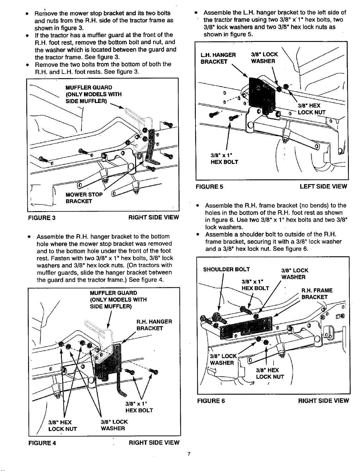
Assemble the L.H. hanger bracket to the left side of
the tractbr frame using two 3/8" xl" hex bolts, two
3/8" lock washers and two 3/8" hex lock nuts as
shown in figure 5.
LH. HANGER
BRACKET
3/8" LOCK
WASHER
3/8" x 1"
HEX BOLT
FIGURE 5
LEFT SIDE VIEW
• Assemble the R.H. frame bracket (no bends) to the
holes in the bottom of the R.H. foot rest as shown
in figure 6. Use two 3/8" x 1" hex bolts and two 3/8"
lock washers.
• Assemble a shoulder bolt to outside of the R.H.
frame bracket, securing it with a 3/8" lock washer
and a 3/8" hex lock nut. See figure 6.
SHOULDER BOLT
3/8 " x 1"
BOLT
3/8" LOCK
WASHER
R.H. FRAME
BRACKET
FIGURE 6 RIGHT SIDE VIEW
7
Loading ...
Loading ...
Loading ...