Loading ...
- 2 -
■STOCK No.62894 ■ PART No.DC15/30
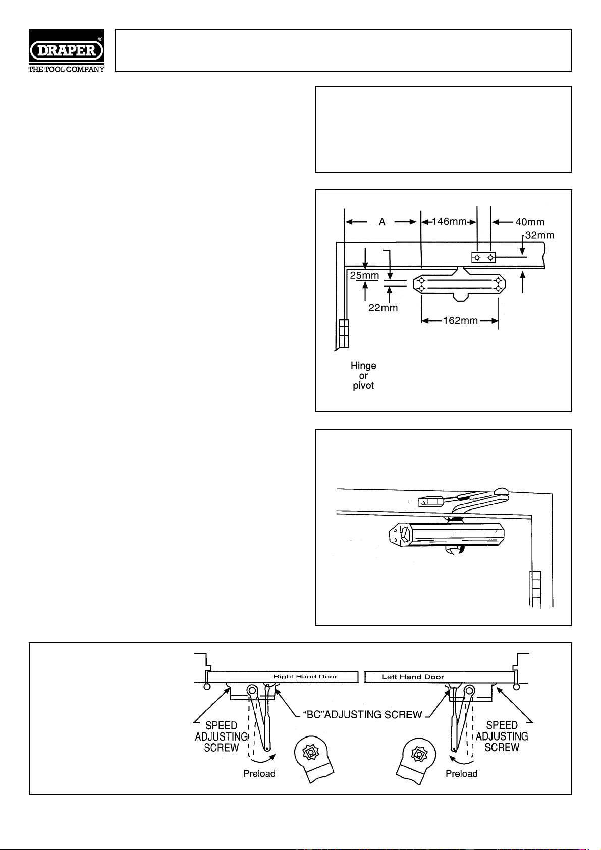
OPENING TO 120°
■DIMENSION A = 95mm
OPENING FROM 120° TO 180°
■DIMENSION A = 65mm
INSTALLATION INSTRUCTIONS FOR
REGULAR ARM (PULL SIDE) MOUNTING
This installation process covers regular arm installa-
tions up to 180° openings.
1. Select the door opening angle and use the dimen-
sions shown opposite. Mark four holes on the door
for the door closer and two holes on the frame for
the arm shoe.
2. Drill 4mmØ pilot holes in the door and frame for the
fixings supplied.
3. Fix the forearm/arm shoe assembly to the door
frame using the fixings supplied.
4. Attach the closer to the door using the fixings sup-
plied.
Note: The speed adjusting valve must be positioned
towards the hinged edge of the door.
5. Install the main arm onto the top pinion shaft, per-
pendicular to the door as illustrated below. Tightly
secure it in place using the screw/washer assembly
supplied.
6. Adjust the length of the forearm so that it is perpen-
dicular to the door frame when assembled to pre-
loaded main arm (see ‘top view’ illustration below).
Secure the forearm to the main arm using the
screw/washer assembly provided.
7. Snap the pinion cap over the pinion shaft at the bot-
tom of the closer unit.
8. Adjust the closing speed of the door using the pro-
cedure detailed on page 5.
REGULAR ARM INSTALLATION
Closer installs on PULL/HINGE side of door
Illustrated
Left Hand Door-LH or
Right Hand Reverse-RHR
TYPICAL TOP VIEW
INSTALLATION
Loading ...
Loading ...
Loading ...