Loading ...
Loading ...
Loading ...
1.PlaceboilerintheselecledIocalion(asnearchimneyaspossible.)Your
boilerisshippedassembled.YouneedonlyIoinsfalltheReliefValveand
adrainlinetocarryanywalerorsteamIoadrain.
2.InstallRelielValveintothe3/,,-pipeonthetopol Iheboiler.SeeFigure5.
Use¾" Pipeandanelbow(nolfurnished)tocarrythewalerorsteamto
anearbydrain.Donotconnectdirectlytoadrainbulleaveanairgap.No
shutollol anydescriptionshallbeplacedbetweenthesafdyrebelvalve
andtheboiler,or ondischargepipesbetweensuchsafetyvalvesandthe
atmosphere.Installationol thesafetyrelielvalveshallconformto the
requirementsof the ANSI/ASMEBoiler and PressureVesselCode,
SeclionIV.Themanulactureris notresponsibleforanywaterdamage.
InstallDrainValvein lowerleftsideofboilerasmarked.
3.ConnectSupplyandReturnLinestoboiler.Theconneclionsmayrequire
certainadditionalfiltingsandparts,asshownondiagram(Figs.5and6).
4.Thisboileris equippedwilh 11/4"supplyandreturnconnectionsonboth
theleftandrightsidesol theboiler.
Inconnectingthecoldwatersupplytothewalerinlelvalve,makesurethat
a cleanwalersupplyis available.Whenthewatersupplyis froma weftor
pump,asandstrainershouldbeinstalledatthepump.
A hotwalerboiler installedaboveradiationlevelmustbeequippedwilha
lowwatercutoffdevice.A periodicinspectionisnecessary,asisflushingof
floattypedevices,permanufacturersspecificinstruction.
FOR USE WITH COOUNG UNITS
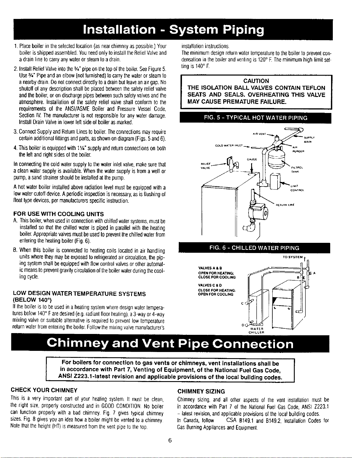
A. Thisboiler,whenusedinconnectionwithchilledwatersystems,mustbe
installedso that thechilledwateris pipedin parallelwiththeheating
boiler.Appropriatevalvesmustbeused1oprevenlthechilledwaterfrom
enteringtheheatingboiler(Fig.6).
B. Whenthisboiler is connectedto heatingcoils locatedin air handling
unitswheretheymaybeexposedtorefrigeratedaircirculation,thepip-
ing syslemshallbeequippedwithflowcontrolvalvesorotherautomaf-
icmeanstoprevenlgravgycirculationoftheboilerwalerduringthecool-
ing cycle.
LOW DESIGN WATER TEMPERATURE SYSTEMS
(BELOW 140°)
If Iheboileristobeusedin aheatingsysfemwheredesignwaterlempera-
luresbelow140° Faredesired(e.g.radianlfloorhealing),a3-wayor4-way
mixingvalveor suitablealternativeis requiredtopreventlowfemperature
returnwaterfromenleringtheboiler.FollowIhemixingvalvemanufacturer's
installationinstructions.
TheminimumdesignreturnwaterLemperatureIotheboilertoprevenlcon-
densationin theboilerandventingis120° ETheminimumhigh limilset-
tingis 140° F.
I CAUTION
THE ISOLATION BALL VALVES CONTAIN TEFLON
SEATS AND SEALS. OVERHEATING THIS VALVE
MAY CAUSE PREMATURE FAILURE.
COt.o WATE_ LNLET.
VALVES A & B
OPEN FOR HEATING;
CLOSE FOR COOLING
VALVES C & O
CLOSE FOR HEATING:
OPEN FOR COOLING
TO SYSTEM
cd
WAFER
CHILLER
For boilers for connection to gas vents or chimneys, vent Installations shall be
in accordance with Part 7, Venting of Equipment, of the National Fue| Gas Code,
ANSI Z223.1-1atest revision and applicable provisions of the local building codes.
CHIMNEY SIZING
CHECK YOUR CHIMNEY
Thisis a very imporfantpartof yourheatingsystem It mustbe clean,
therightsize,properlyconstructedandin GOODCONDITIONNo boiler
canlunctionproperlywith a bad chimney.Fig. 7 givestypicalchimney
sizes.Fig.8 givesyouanideahowa boilermightbe ventedto achimney
Nofetha_theheight(HT)ismeasuredfromtheventpipetothelop.
Chimneysizing,and all otheraspectsof the vent installationmustbe
in accordancewith Part7 of the NationalFuelGasCode,ANSIZ223.1
- laleslrevision,andapplicableprovisionsofthelocalbuildingcodes.
In Canada,follow CSA B149.1and B149.2,InstallabonCodesfor
GasBurningAppliancesandEquipment.
6
Loading ...
Loading ...
Loading ...