L.P.
CONVERSION
INSTRUCTIONS
Ay
WARNING:
This
conversion
must
be
performed
by
a
qualified
installer
or
gas
supplier
in
accordance
with
the
manufacturer's
instructions
and
all
codes
and
requirements
of
the
authority
having
jurisdiction.
Failure
to
follow
ALL
instructions
could
result
in
serious
injury
or
property
damage.The
qualified
agency
performing
this
work
assumes
responsibility
for
the
conversion.
The
pressure
regulator
and
the
burner
orifices
are
set
for
natural
gas.
To
use
Liquid
Propane
Gas, the
regulator
and
burner
orifices
must
be
converted.
The
L.P.
orifices
for
the
cooktop
burners
are
shipped
on the
regulator
bracket
behind
the
storage
drawer.
Also,
in
the
same
area,
is
a
second
bracket
holding
the
L.P.
15K
orifice
extended
spud,
choke
and
set
screw
for
the
front
right
Extra
Large
cooktop
burner
(on
models
so
equipped).
Remove
the
storage
drawer
to
locate.
A.
WARNING:
Do
not
operate
the
cooktop
or
oven
burners
of
this
range
when
using
L.P.
(bottled)
gas
before
converting
the
pressure
regulator
and
burner
orifices
for
L.P.
gas
use.
Failure
to
do
so
could
cause
high
flames
and
toxic
fumes
which
can
result
in
serious
injury.
NOTICE:
if
you
are
using
LP.
(bottled)
gas,
all
adjustments
described
inthe
following
steps
must
be
made
before
you
make
any
burner
adjustments.
To
adjust
your
range
for
use
with
LP.
gas,
follow
these
instructions:
1.
Disconnect
all
electrical
power,
at
the
main
circuit
breaker
or
fuse
box.
2.
Shut
off
the
gas
supply
to
the
range
by
closing
the
manual
shut-off
valve.
a.
Raise
the
cooktop
and
locate
the
pressure
regulator.
b.
Follow
the
direction
in
1A
or
1B
depending
on
your
regulator
type.
Regulator
pictured
may
be
differ
fromm
your
model.
1A-iF
THIS
IS
YOUR
REGULATOR
(LP/Propane)
Converter
Nut&Pin
GasFlow
IntoRange
a.
Use
an
adjustable
wrench
to
remove
the
hex-nut
from
the
pressure
regulator.
b.
Apply
sideward
finger
pressure
to
remove
the
plastic
pin
from
the
nut.
Note:
To
remove
the
pin,
place
the
nut
on
a
flat
surface
and
press
the pin
sideways
with
your
fingers.
c.
Rotate
the
pin
180
degrees
and
snap
the
pin
back
into
the
nut.
NAT
Vent
(LP/Propane)
d.
Reinsert
the
assembly
into
the
regulator
and
tighten
the
hex-nut.
(Do
nor
over
tighten)
1B-IF
THIS
IS
YOUR
REGULATOR
Use
an
adjustable
wrench
to
unscrew
the
hex-nut
cap
from
the
pressure
regulator.
Apply
pressure
and
turn
counter
clockwise
to
disassembly
the
plastic
cap.
Turn
the
cap
over
and
hook
it
into
the
slots.
The
type
of
gas
to
be
used
should
now
be
visible
in
the
top
of
the
cap.
Screw
back
the
hex-nut
cap
into
the
pressure
regulator.
Lift
the
burner
assemblies
straight
up
(set
aside}
to
gain
access
to
the
surface
burner
orifice
spuds.
Natural
Gas
LP
Gas
Brass
Sliver
Using
a
5/16”
nut
driver
or
adjustable
wrench,
remove
each
of
the
four
(4)
spuds
on
the
surface
burner
gas
inlet
tubes.
Replace
them
with
the
correct
gas
spuds
mounted
in
a
holder
at
the
right
rear
of
the
range,
above
the
regulator.
(Natural
gas
spuds
are
"BRASS"
and
LP
gas
spuds
are
“SILVER")
NOTICE:
Save
these
orifices
for
future
conversion
back
to
natural
gas.
.
Located
the
thermostat
pilot
Return
the
spuds
you
removed
from
the
inlet
tubes
to
the
holder
above
the
regulator.
(To
prevent
leakage,
make
sure
the
spuds
are
securely
screwed
into
the
gas
inlet
tubes).
Replace
the
burner
assemblies.
Remove
all
five
(5)
knobs,
including
OVEN
CONTROL
Knob.
Remove
the
four
(4)
screws
located
behind
the
two
(2)
inner
cooktop
knobs.
.
Open
the
oven
door.
Remove
the
three
(3)
screws
located
under
the
mainfold
panel.
Remove
the
mainfold
panel.
.
Located
the
thermostat
bypass
screw
below
the
thermostat
shaft.Completely
loosen
the
natural
gas
bypass
screw
(blue)
by
turning
it
counterclockwise.
Remove
it
by
gently
pulling
it
out
using
pliers.
.
Replace
with
the
LP
bypass
screw
(white)
located
in
the
envelope
near
the
rear
of
the
range,
above
the
pressure
regulator.
Tighten
the
screw
by
turning
it
clockwise.
Turn
Screws
Counter
clockwise
to
loosen
flame
screw
to
the
right
of
the
thermostat
shaft.
Completely
loasen
the
natural
gas
pilot
screw
(red)
by
turning
it
counterclockwise
Remove
it
by
gently
Fee
coves
leak
pulling
it
out
using
similar,
please
see
-
chart
below
for
Pliers.
correct
screw
LP
or
Nat
f,
Replace
with
the
LP pilot
screw
(black)
located
in
the
envelope
near
the
rear
of
the
range,
above
the
pressure
regulator.
Tighten
the
screw
by
turning
it
clockwise.
g.
Replace
manifold
panel
and
knobs.
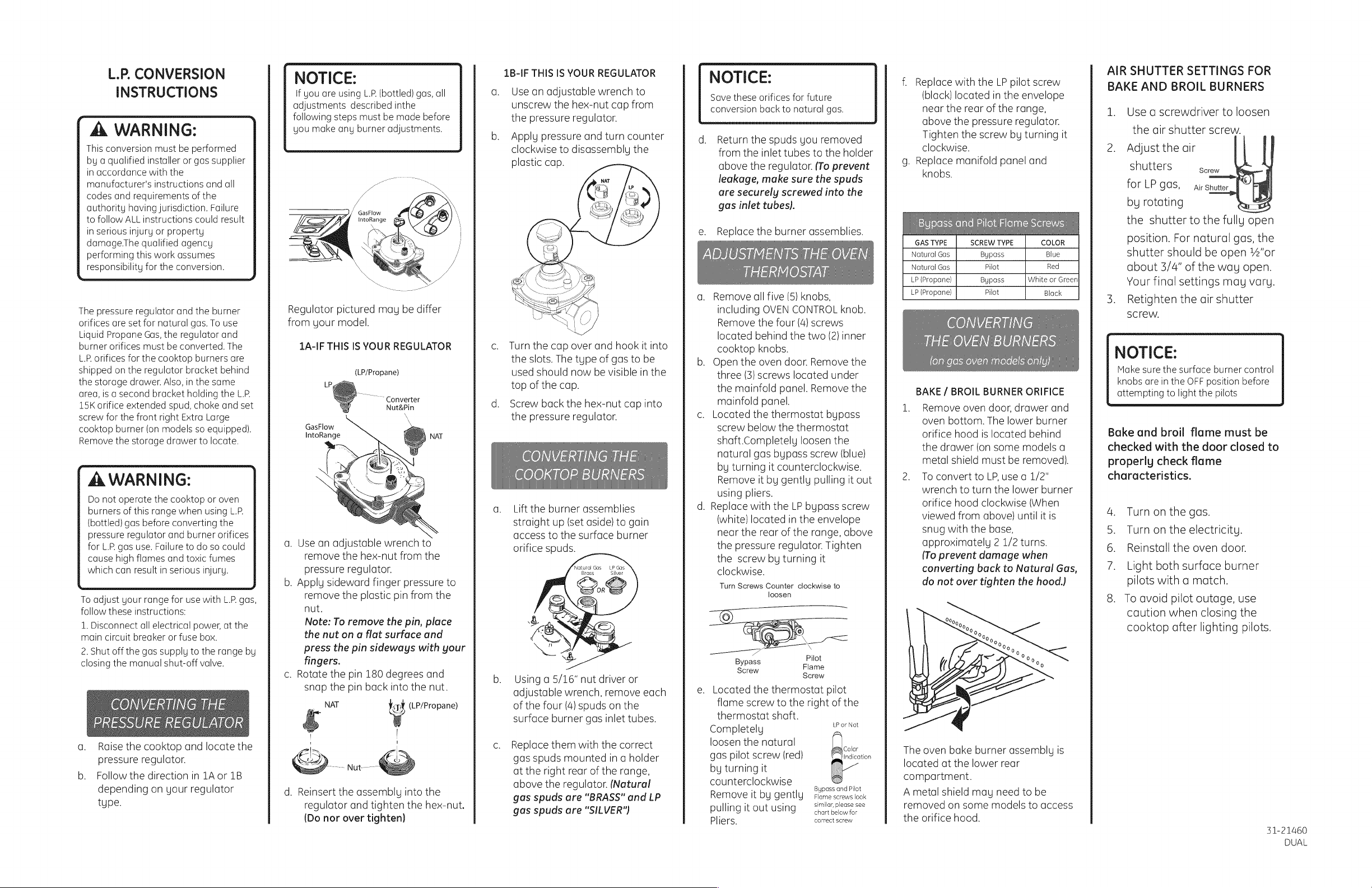
GAS
TYPE
SCREW
TYPE
COLOR
Natural
Gas
Bypass
Blue
Natural
Gas
Pilot
Red
LP
(Propane)
Bypass
White
or
LP
(Propane)
Pilot
Black
BAKE
/
BROIL
BURNER
ORIFICE
1.
Remove
oven
door,
drawer
and
aven
bottom.
The
lower
burner
orifice
hood
is
located
behind
the
drawer
(on
some
models
a
metal
shield
must
be
removed).
2.
To
convert
to
LP,
use
a
1/2”
wrench
to
turn
the
lower
burner
orifice
hood
clockwise
(When
viewed
from
above}
until
it
is
snug
with
the
base,
approximately
2
1/2
turns.
(To
prevent
damage
when
converting
back
to
Natural
Gas,
do
not
over
tighten
the
hood.)
The
oven
bake
burner
assembly
is
located
at
the
lower
rear
compartment.
A
metal
shield
may
need
to
be
removed
on
some
models
to
access
the
orifice
hood.
AIR
SHUTTER
SETTINGS
FOR
BAKE
AND
BROIL
BURNERS
1.
Use
a
screwdriver
to
loosen
the
air
shutter
screw.
2.
Adjust
the
air
shutters
Screw
for
LP
gas,
Air
Shutter
.
em)
by
rotating
+
the
shutter
to
the
fully
open
position.
For
natural
gas,
the
shutter
should
be
open
%4’or
about
3/4”
of
the
way
open.
Your
final
settings
may
vary.
3.
Retighten
the
air
shutter
Screw.
NOTICE:
Make
sure
the
surface
burner
control
knobs
are
in
the
OFF
position
before
attempting
to
light
the
pilots
Bake
and
broil
flame
must
be
checked
with
the
door
closed
to
properly
check
flame
characteristics.
4.
Turnon
the
gas.
5.
Turn
on
the
electricity.
6.
Reinstall
the
oven
door.
7.
Light
both
surface
burner
pilots
with
a
match.
To
avoid
pilot
outage,
use
caution
when
closing
the
cooktop
after
lighting
pilots.
@e
31-21460
DUAL
ADJUSTING
THE
SURFACE
BURNER
PILOTS
1.
Locate
the
pilot
adjustment
screw.
It
can
be
accessed
through
the
small
hole
near
the
center
of
the
manifold
panel.
2.
To
adjust,
use
a
flat-blade
screwdriver
with
a
shaft
diameter
of
less
than
3/16”.
Turn
the
pilot
adjustment
screw
until
the
pilot
is
5/16”
high.Do
not
reduce
the
flame
to
less
than
5/16”
or
a
pilot
outage
may
occur.
A
pilot
flame
burning
higher
than
recommended
may
generate
soot
{carbon
black)
on
the
bottom
of
the
cooktop.
LIGHTING
THE
OVEN
PILOT.
1.
Locate
the
pilot
in
the
back
of
the
oven bottom.
The
pilot
is
attached
to
the
left
side
of
the
oven
burner.
2.
To
light
the
oven
pilot,
push
in
and
hold
the
oven
control
knob
while
lighting
the
pilot
with
a
long
match
or
match
holder.
Once
the
oven
pilot
is lit,
continue
holding
the
oven
control
knob
for
one
minute
before
control
knob
for
one
minute
before
releasing.
3.
The
pilot
flame
size
should
be
approximately
3/8
for
LP
and
Y
for
natural
gas.
CHECKING
THE
FLAME
SIZE
A
WARNING:
if
you
attempt
to
measure
the
inner
cone
of
the
flame,
please
use
caution;
burns
could
result.
1.
Checking
the
flame
size:
Check
the
inner
cone
of
the
flame.
It
should
be
approximately
%”
to
¥%,”
long
for
the
bake
and
broil
burners.
INNER
CONE
OF
FLAME
4/2”
to
3/4”
a
OVEN
/
BROIL
(\
a’
BURNER
~s
CHECKING
THE
FLAME
QUALITY
The
combustion
quality
of
the
burner
flames
need
to
be
determined
visually.
NOTE:
If
burner
flames
look
like
(A).
Further
air
shutter
adjust-
ment
is
required.
Normal
burner
flames
should
look
like
(B)
or
(C),
depending
on
the
type
of
gas
you
use.
With
LP
gas,
some
yellow
tipping
on
the
outer
cones
is
normal.
(A)
Yellow
Flames:
Further
Adjustment
29)
Required
(B})
Yellow
tips
on
7
outer
cones:
Normal
for
LP
Gas
{C}
Soft
Blue
Flames:
Normal
for
Natural
Gas.
When
all
adjustments
are
made
and
the results
are
satisfactory:
a.
Replace
the
orifice
fitting
cover.
b.
Replace
the
oven
baffle
(flame
spreader).
c.
Replace
the
oven
bottom.
IN
SOME
CASES:
a.
With
L.P.
gas,
some
yellow
tipping
on
the
outer
cone
is
normal.
b.
Foreign
particles
in
the
gas
line
may
cause
an
orange
flame
at
first,
but
this
will
soon
disappear.
SPECIAL
NOTE:
To
convert
the
oven
back
to
natural
gas,
reverse
the
instructions
given
in
making
L.P.
Adjustments.
REPLACE
OVEN
PARTS
Replace
the
oven
bottom,
oven
racks,
oven
door
and
broil
drawer.
NOTICE:
Once
the
conversion
is
complete
and
checked
ok,
fill
out
the
L.P.
Sticker
and
include
your
name,
organization
and
cate
conversion
was
made.
Apply
the
sticker
to
the
range
near
the
regulator
to
alert
others
in
the
future
that
this
appliance
has
been
converted
to
L.P.
If
converting
back
to
natural
gas
from
L.P,
please
remove
the
sticker
so
others
know
the
appliance
is
set
to
use
natural
gas.
|
Hi
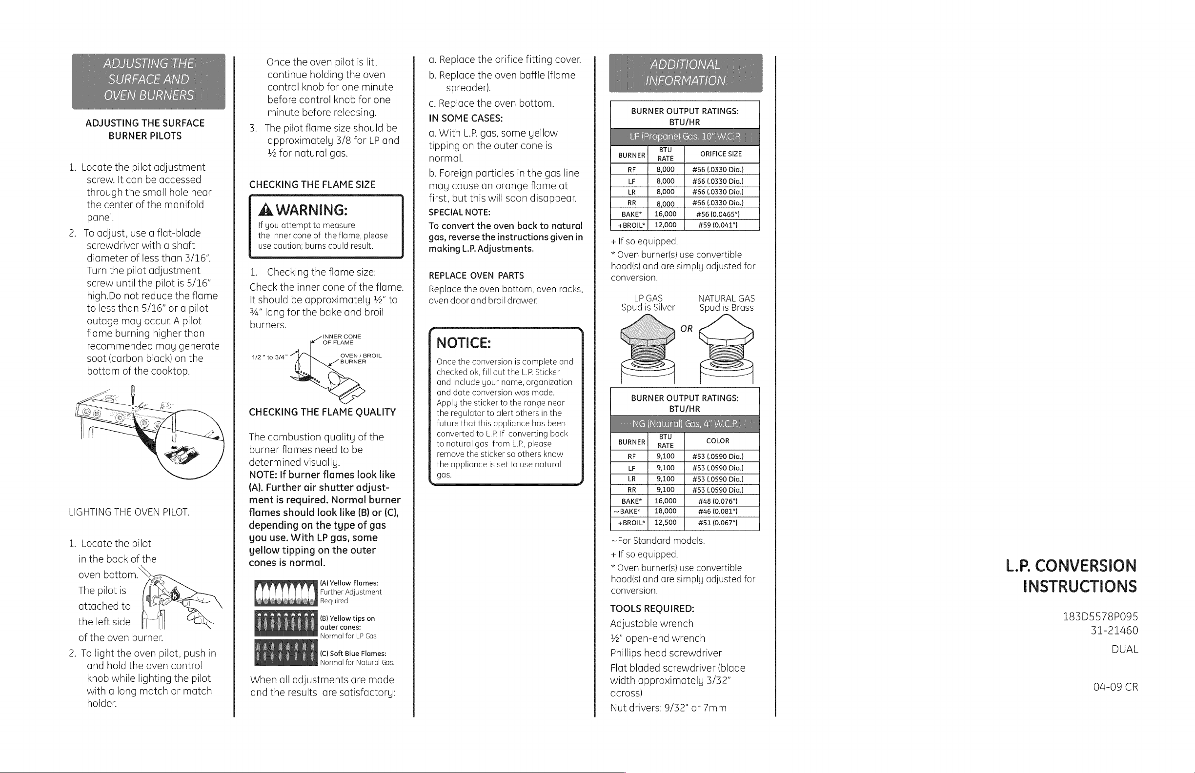
BURNER
OUTPUT
RATINGS:
BTU/HR
BURNER|
pate
ORIFICE
SIZE
RF
8,000
#66
(.0330
Dia.)
LF
8,000
#66
(.0330
Dia.)
LR
8,000
#66
(.0330
Dia.)
RR
8,000
#66
(.0330
Dia.)
BAKE*
|
16,000
#56
(0.0465"}
+BROIL*|
12,000
#59
(0.041")
+
lf
so
equipped.
*
Oven
burner(s}
use
convertible
hood(s}
and
are
simply
adjusted
for
conversion.
LP
GAS
NATURAL
GAS
Spud
is
Silver
Spud
is
Brass
OR
BURNER
OUTPUT
RATINGS:
BTU/HR
BTU
BURNER)
pare
COLOR
RF
9,100
#53
(.0590
Dia.}
LF
9,100
#53
(.0590
Dia.)
LR
9,100
#53
(.0590
Dia.)
RR
9,100
#53
(.0590
Dia.)
BAKE*
|
16,000
#48
(0.076")
~
BAKE*
18,000
#46
(0.081")
+BROIL*|
12,500
#51
(0.067")
~For
Standard
models.
+
If
so
equipped.
*
Oven
burner(s}
use
convertible
hood(s}
and
are
simply
adjusted
for
conversion.
TOOLS
REQUIRED:
Adjustable
wrench
Ys”
open-end
wrench
Phillios
head
screwdriver
Flat
bladed
screwdriver
(blade
width
approximately
3/32”
across}
Nut
drivers:
9/32"
or
7mm
L.P.
CONVERSION
INSTRUCTIONS
183D5578P095
31-21460
DUAL
04-09
CR