Loading ...
Loading ...
Loading ...
2. CONTENTS
- 3 -
- 10 -
Depending on manufacture and model, some engine components do change. Please check with
Autodata or the manufacturer’s data before use.
1. TITLE PAGE
1.1 INTRODUCTION.......................................................................................................... 2
1.2 REVISION HISTORY .................................................................................................. 2
1.3 UNDERSTANDING THIS GUIDE................................................................................. 2
1.4 COPYRIGHT NOTICE .................................................................................................2
2. CONTENTS
2.1 CONTENTS ....................................................................................................................3
3. GUARANTEE
3.1 GUARANTEE ............................................................................................................... 4
4. GENERAL PRODUCT INFORMATION
4.1 GENERAL PRODUCT INFORMATION ....................................................................... 5
5. HEALTH AND SAFETY INFORMATION
5.1 GENERAL SAFETY INSTRUCTIONS FOR USE
Personal safety........................................................................................................... 6
6. CONTENTS
6.1 PARTS DRAWING AND LISTING ............................................................................... 7
7. APPLICATION
7.1 PRODUCT APPLICATION AND COMPATIBILITY LISTING ...................................... 8
8. PREPARATION
8.1 ADVISORIES BEFORE USE ...................................................................................... 9
9. PROCEDURE AND APPLICATION GUIDE
9.1 APPLICATION GUIDANCE........................................................................................10
10. EXPLANATION OF SYMBOLS
10.1 EXPLANATION OF SYMBOLS .................................................................................. 11
9. PROCEDURE AND APPLICATION GUIDE
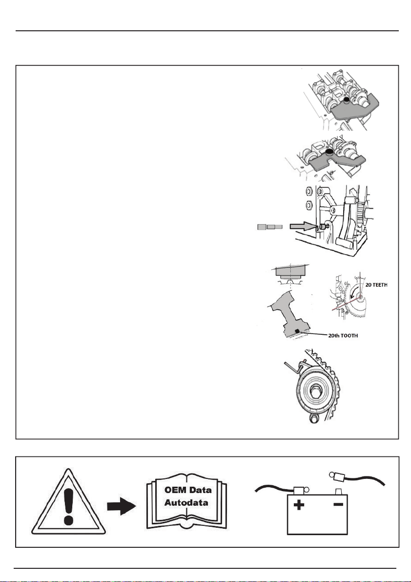
Component 3 = Camshaft alignment plate pre 01/05/2011.
Install 1 or 3 as required after component 5 has been installed. It may
be necessary to turn the camshafts a small amount, if required use an
appropriate wrench on the hexagons on the cams. Note: when
tightening or loosening the cam pulleys always hold the camshafts
with a suitable wrench on the hexagons on the camshafts.
Component 1 = Camshaft alignment plate post 02/05/2011.
Component 5 = Crankshaft timing pin, designed to screw into the
engine block. Turn the crankshaft to just before TDC, fit component 5
as shown then turn the crankshaft till it contacts 5. As shown.
Component 2 = Tensioner Pin, used to lock the cam chain
tensioner in its retracted position as shown.
Component 4 = Crankshaft Position Sensor Alignment
Tool, used to align the crankshaft position sensor when
refitting. The crankshaft sensor is mounted on a slotted
bracket that allows the sensor position to be adjusted.
Component 4 slides onto the sensor and on to the 20th tooth
from the gap in the teeth on the front pulley. In this way it both
aligns the sensor with the correct tooth and sets the required
distance from the tooth.
Please note images are for guidance only and subject to change.
Loading ...
Loading ...