Loading ...
Loading ...
4, ASSEMBLY PROCEDURE.
(See figure 5 for index numbnrsQ
a, Remove 'the four cover retaining knobs (1) and slide
the cover (2) off the studs, (See figure _,,)
CAUTION: Unscrew the leveling screw (67,
figure 5)_ until the end & flesh with the back
slde of trunnion support bracket (46),
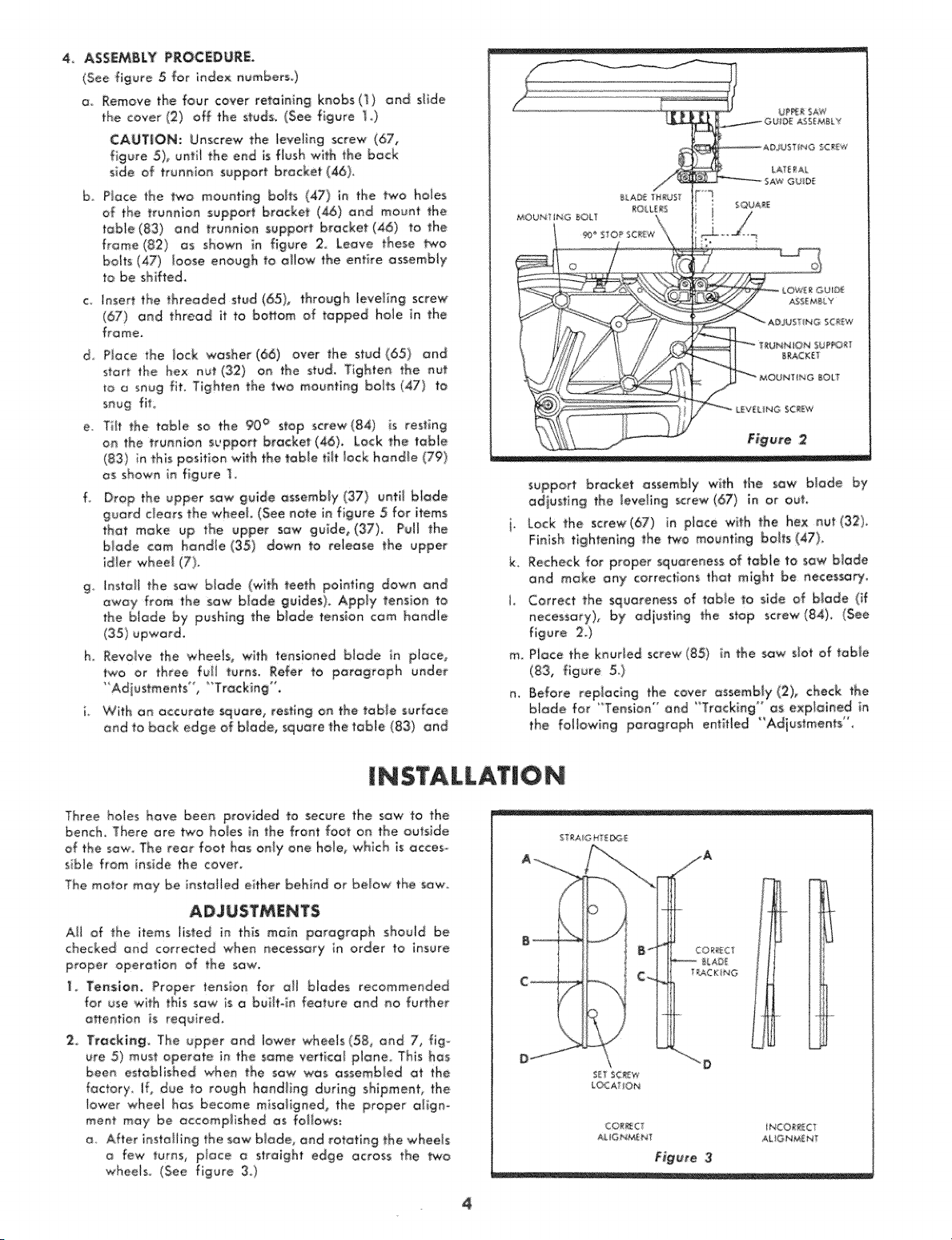
b Piece the _o mountieg brits (47) in the two hales
of the trunnion support bracket (_)oed mount the
table(83) end trunnion support bracket (46) to the
f:rome (82) os shown in: figure 2._Leave: these two
bolts (47) _eose enough to allow the eetbe assembly
to be shifted.
c, _nsert the threaded stud (65), through _eve_in,g screw
(67) _nd thread it to bo_om of tapped hole in the
frame,
d, Piece the lock washer (66), over the _tud (651 and
_tort the hex nut (132) on the stud Tighten the nut
u_ a seug fit, Tighten the two meuetieg bobs (47) to
snug fiL
e, Tit the table so the 90° stop screw(84) is resting
on the truen_on support bracket (46), Lock the table
(83) in this position with the tQb_etiff lock handle (79)
as shown in figure ]
f, Drop the upper sow guide assembly (37') until b_ade
guard clears the whoa!, (See note in figure 5 for items
that make up the upper saw guide, (37), Pull the
blade cam handle (35) down to release the upper
_dler wheel (7},
g install the saw blade (with teeth pointing down and
away from the saw blade guides), Apply tension to
the blade by pushing the blade tension cam handl÷
(35) upward_
h, Revalue the whoa!s, with tensioned Made in piece,
two or three fuji turns_ Refer to paragraph under
"Adiustments" , "T_acking '°.
i, With on accurate _uare, resting on the table surface
and to back edge air blade, square the table (83) and
support br'_cke_ assembly with the sow blade by
adjusting the lauding screw (67) in or eu)
i. Lock _he screw(67} in place wlth the h÷× out (32)
Finish tightening the _0 mounting barfs (47),
k. Recheck for propersquareness of table to s_w btade
and make any corrections that might be aeces_Fy
J Correct the squareness af table to side ef blade (if
necessary), by adjus_ieg the stop screw (84), (See
figure 2.}
m_ Place the keurled screw (85_ in the saw slot of tome
(83, figure 5_)
n, Before replacing the cover _ssembJy (2), check the
biade for "Tension" end "TrackMg" as expi_ieed in
the following paragraph entiHed
I $TALLATIO
Three holes have been p_ovided to :secure the saw _o, the
bench There are two holes in the front foot on the ouiside
of the sow The rear foot has only one hole, which is _cces-
sible from inside the cev'er,
The motor may be iest'aI_ed either behind or below the saw
A!l of the i_ems Iisted in this maie paragraph should be
checked and corrected when _ecessary in order to insure
proper operation of the sow,,
1, Te_slom Proper' tensioe for a[[ biades recommended
for use with this sow is o buihoin feature and _0 further
o#eetioe is required,
2, Trecki_g_ The upper and lower wheels (58, end 7, fig°
ure 5) must operate in, the some vertical p!_e, This has
been estob!ished when the sow was assembled _t the
factory, if, due to rough hand_ing during shipment, the
lower wheel has become misoligned, the proper a!igno
meet may be accomplished as fe|iows:
a After installing the sow blade, and rotating the wheels
few turns, place o strolgh_ edge across the two
wheels, (See figure 3)
ST_AiG HTE_E
CORAC iNCORReCT
AIL _G_ME _ t AJ. IG _E N
Figure 3
4
Loading ...
Loading ...
Loading ...