
Owner's Manual
CRAFTS[MAN+
15.5 HP
ELECTRIC START
42" MOWER
6 SPEED TRANSAXLE
LAWN TRACTOR
Model No.
917.271014
• Safety
• Assembly
• Operation
• Maintenance
• Repair Parts
CAUTION:
Read and follow all
Safety Rules and Instructions
before operating this equip-
ment
For answers to your questions
about this product, Call:
1-800-659-5917
Sears Craftsman Help Line
5 am - 5 pro, Mon - Sat
Sears, Roebuck and Co., Hoffman Estates, IL 60179
Visit our Craftsman website: www.sears.com/craftsman
.Warranty...............................................2
SafetyRules..:......................................2
ProductSpecifications .......................... 5
Assembly .............................................. 8
Operation ............................................ 12
Maintenance Schedule ...................... 18
Maintenance ....................................... 18
Service and Adjustments .................... 22
Storage ............................................... 28
Troubleshooting .................................. 29
Repair Parts ........................................ 34
Parts Ordering ..................... Back Cover
LIMITED TWO YEAR WARRANTY ON CRAFTSMAN RIDING EQUIPMENT
For two (2) years from the date of purchase, if this Craftsman Riding Equipment is
maintained, lubricated and tuned up according to the instructions in the owner's
manual, Sears will repair or replace, free of charge, any parts found to be defective in
material or workmanship.
This Warranty does not cover:
• Expendable items which become worn during normal use, such as blades, spark
plugs, air cleaners, belts, etc.
• Tire replacement or repair caused by punctures from outside objects, such as nails,
thorns, stumps, or glass.
• Repairs necessary because of operator abuse, negligence, improper storage or ac-
cident or the failure to maintain the equipment according to the instructions con-
tained in the owner's manual.
• Riding equipment used for commercial or rental purposes.
LIMITED 90 DAY WARRANTY ON BATI-ERY
For ninety (90) days from date of purchase, if any battery included with this riding
equipment proves defective in material or workmanship and our testing determines the
battery will not hold a charge, Sears will replace the battery at no charge. In-home war-
ranty service on your Craftsman riding equipment is available at no charge for 30 days
from the date of purchase. Please contact your nearest service center. After 30 days
from the date of purchase, warranty service is available by taking your Craftsman
riding equipment to your nearest Sears Service Center. (In-home warranty service will
still be available after 30 days from the date of purchase but e standard trip charge will
apply). This warranty applies only while this product is in the United States. This War-
ranty gives you specific legal rights, and you may also have other rights which may
vary from state to state.
Sears, Roebuck and Co., 1:)/817 WA, Hoffman Estates, IL 60179
IMPORTANT: This cutting machine is ca-
pable of amputating hands and feet and
throwing objects. Failure to observe the
following safety instructions could result
in serious injury or death.
GENERAL OPERATION
• Read, understand, and foJlow all in-
structions in the manual and on the ma-
chine before starting.
• Only allow responsible adults, who are
familiar with the instructions, to operate
the machine.
• Clear the area of objects such as rocks,
toys, wire, etc., which could be picked
up and thrown by the blade.
• Be sure the area is clear of other
peo.ple before mowing. Stop machine if
anyone enters the area.
• Never carry passengers.
• Do not mow in reverse unless abso-
lutely necessary. Always look down and
behind before and while backing.
• Be aware of the mower discharge di-
rection and do not point it at anyone.
Do not operate the mower without ei-
ther the entire grass catcher or the
guard in place.
• Slow down before turning.
• Never leave a running machine unat-
tended. Always turn off blades, set
parking brake, stop engine, and re-
2 move keys before dismounting.

• Turn off blades when not mowing.
• Stop engine before removing grass
catcher or unclogging chute.
• Mow only in daylight or good artificial
light.
• Do not operate the machine while un-
der the influence of alcohol or drugs.
• Watch for traffic when operating near or
crossing roadways.
• Use extra care when loading or un-
loading the machine into a trailer or
truck.
• Data indicates that operators, age 60
years and above, are involved in a
large percentage of riding mower-re-
lated injuries. These operators should
evaluate their ability to operate the
riding mower safely enough to protect
themselves and others from serious in-
jury.
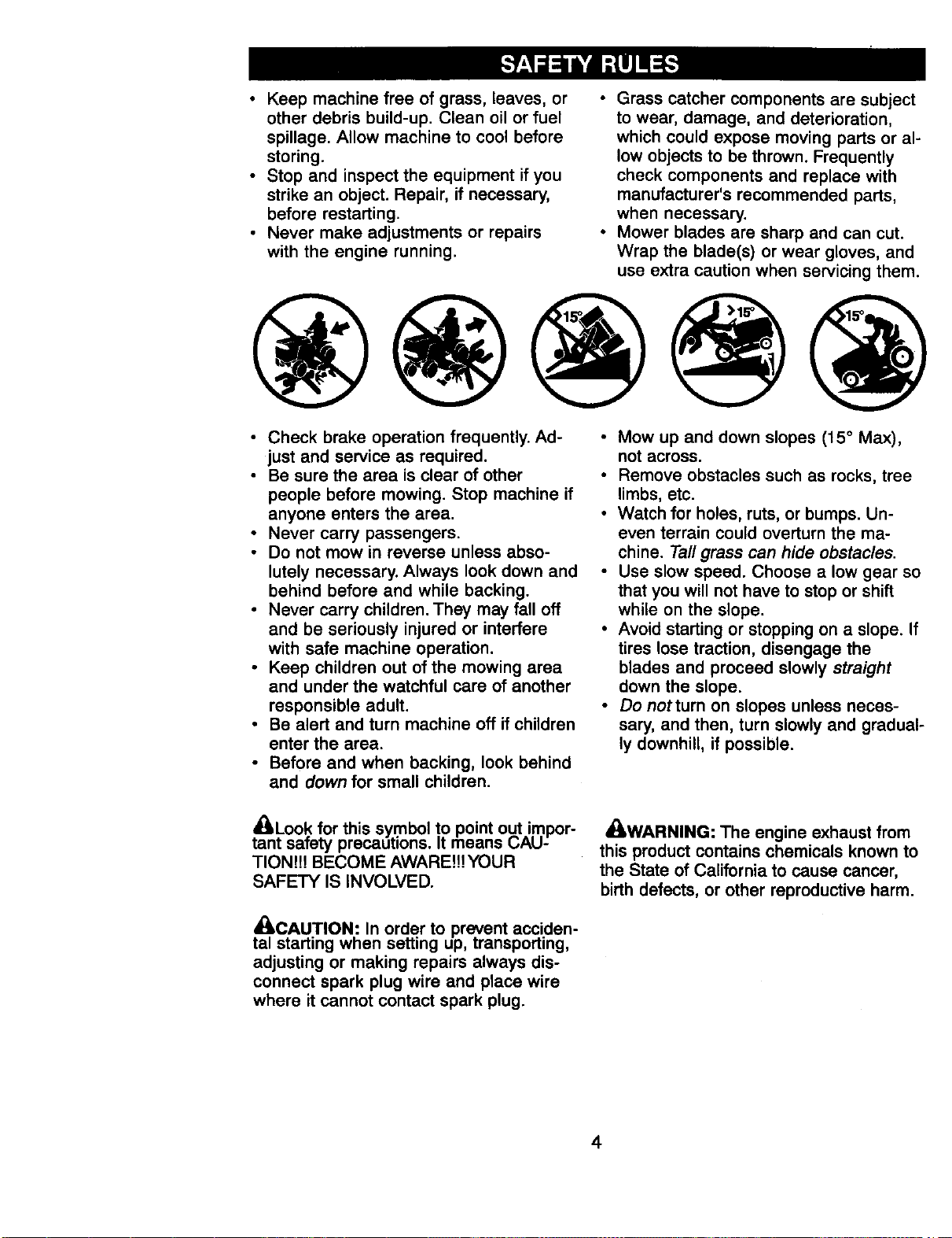
SLOPE OPERATION
Slopes are a major factor related to loss-
of-control and tipover accidents, which
can result in severe injury or death. All
slopes require extra caution. If you cannot
back up the slope or if you feel uneasy on
it, do not mow it.
DO:
• Mow up and down slopes, not across.
• Remove obstacles such as rocks, tree
limbs, etc.
• Watch for holes, ruts, or bumps. Un-
even terrain could overturn the ma-
chine. Tall grass can hide obstacles.
• Use slow speed. Choose a low gear so
that you will not have to stop or shift
while on the slope.
• Follow the manufacturer's recommen-
dations for wheel weights or counter-
weights to improve stability.
• Use extra care with grass catchers or
other attachments. These can change
the stability of the machine.
• Keep all movement on the slopes slow
and gradual. Do not make sudden
changes in speed or direction.
• Avoid starting or stopping on a slope. If
tires lose traction, disengage the
blades and proceed slowly straight
down the slope.
DO NOT:
• Do notturn on slopes unless neces-
sary, and then, turn slowly and gradual-
ly downhill, if possible.
Do not mow near drop-offs, ditches, or
embankments. The mower could sud-
denly turn over if a wheel is over the
edge of a cliff or ditch, or if an edge
caves in.
Do not mow on wet grass. Reduced
traction could cause sliding.
Do not try to stabilize the machine by
putting your foot on the ground.
Do not use grass catcher on steep
slopes.
CHILDREN
Tragic accidents can occur if the operator
is not alert to the presence of children.
Children are often attracted to the ma-
chine and the mowing activity. Never as-
sume that children will remain where you
last saw them.
• Keep children out of the mowing area
and under the watchful care of another
responsible adult.
• Be alert and turn machine off if children
enter the area.
• Before and when backing, look behind
and down for small children.
• Never carry children. They may fall off
and be seriously injured or interfere
with safe machine operation.
• Never allow children to operate the ma-
chine.
• Use extra care when approaching blind
corners, shrubs, trees, or other objects
that may obscure vision.
SERVICE
• Use extra care in handling gasoline
and other fuels. They are flammable
and vapors are explosive.
Use only an approved container.
Never remove gas cap or add fuel
with the engine running. Allow en-
gine to cool before refueling. Do not
smoke.
Never refuel the machine indoors.
Never store the machine or fuel
container inside where there is an
open flame, such as a water heater.
• Never run a machine inside a closed
area.
• Keep nuts and bolts, especially blade
attachment bolts, tight and keep equip-
ment in good condition.
• Never tamper with safety devices.
Check their proper operation regularly.
3
• Keep machine free of grass, leaves, or
other debris build-up. Clean oil or fuel
spillage. Allow machine to cool before
storing.
• Stop and inspect the equipment if you
strike an object. Repair, if necessary,
before restarting.
• Never make adjustments or repairs
with the engine running.
• Grass catcher components are subject
to wear, damage, and deterioration,
which could expose moving parts or al-
low objects to be thrown. Frequently
check components and replace with
manufacturer's recommended parts,
when necessary.
• Mower blades are sharp and can cut.
Wrap the blade(s) or wear gloves, and
use extra caution when servicing them.
• Check brake operation frequently. Ad-
just and service as required.
• Be sure the area is clear of other
people before mowing. Stop machine if
anyone enters the area.
• Never carry passengers.
• Do not mow in reverse unless abso-
lutely necessary. Always look down and
behind before and while backing.
• Never carry children. They may fall off
and be seriously injured or interfere
with safe machine operation.
• Keep children out of the mowing area
and under the watchful care of another
responsible adult.
• Be alert and turn machine off if children
enter the area.
• Before and when backing, look behind
and down for small children.
• Mow up and down slopes (15 ° Max),
not across.
• Remove obstacles such as rocks, tree
limbs, etc.
• Watch for holes, ruts, or bumps. Un-
even terrain could overturn the ma-
chine. Tall grass can hide obstacles.
• Use slow speed. Choose a low gear so
that you will not have to stop or shift
while on the slope.
• Avoid starting or stopping on a slope. If
tires lose traction, disengage the
blades and proceed slowly straight
down the slope.
• Do notturn on slopes unless neces-
sary, and then, turn slowly and gradual-
ly downhill, if possible.
_i_LLoo.k for this symbol to point out.impor-
tant saTety precautions. It means L;AU-
TION!H BECOME AWARE!!!YOUR
SAFETY IS INVOLVED.
._. CAUTION.: In order to prevent acciden-
tal starting wnen setting up, transporting,
adjusting or making repairs always dis-
connect spark plug wire and place wire
where it cannot contact spark plug.
_LWARNING: The engine exhaust from
this product contains chemicals known to
the State of California to cause cancer,
birth defects, or other reproductive harm.
4
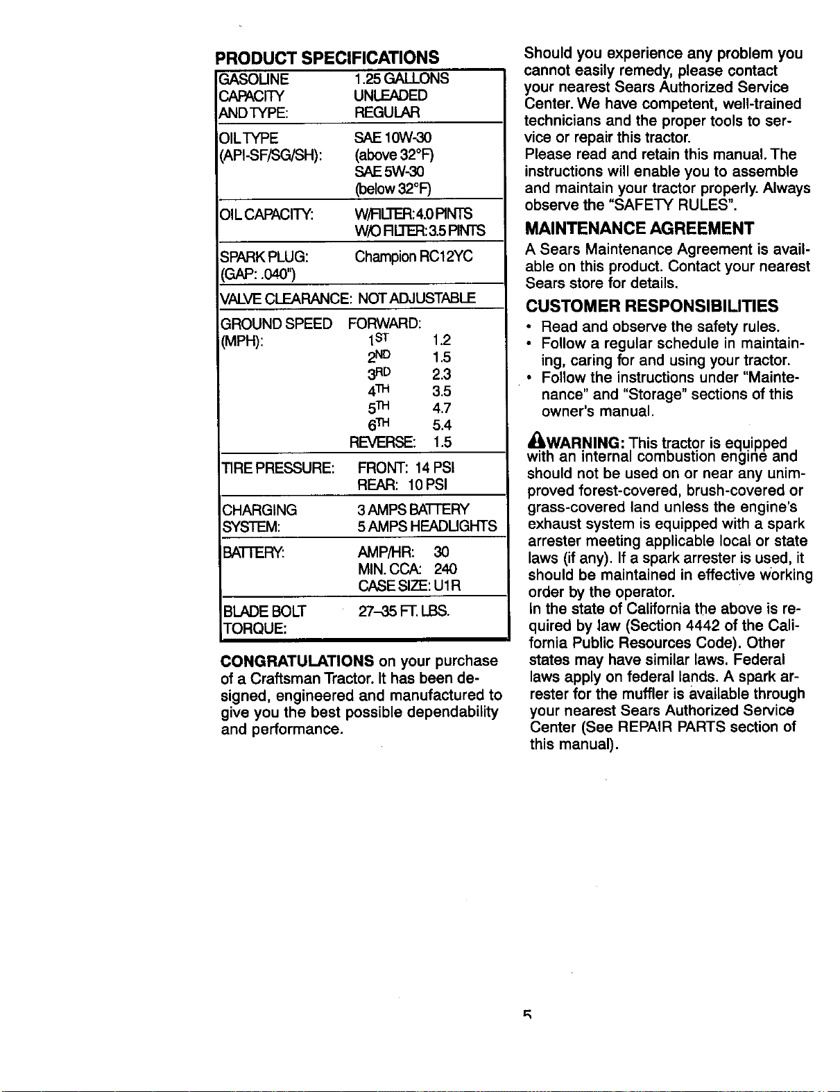
PRODUCT SPECIFICATIONS
GASOUNE 1.25GALLONS
CAPACITY UNLEADED
ANDTYPE: REGULAR
)ILTYPE SAE IOW-30
API-SF/SG/SH): (above 32°F)
SAE 5W-30
(below 32°F)
OIL CAPACITY." W/FIL'I'B:_:4.0PINTS
W/O RL]E_ &5 PINTS
SPARK PLUG: Champion RC12YC
(GAP:.040")
VALVE CLEARANCE: NOT ADJUSTABLE
GROUND SPEED
VlPH):
FORWARD:
1s-r 1.2
2ND 1,5
3RD 2.3
4n_ 3.5
5TH 4.7
6_ 5.4
REVERSE: 1.5
TIRE PRESSURE: FRONT: 14 PSI
REAR: 10 PSI
_HARGING 3 AMPS BATTERY
SYSTEM: 5 AMPS HEADUGHTS
BATTERY: AMP/HR: 30
MIN. CCA: 240
CASE SIZE: U1R
BLADE BOLT 27-35 FT.LBS.
TORQUE:
CONGRATULATIONS on your purchase
of a Craftsman Tractor.It has been de-
signed, engineered and manufactured to
give you the best possible dependability
and performance.
Should you experience any problem you
cannot easily remedy, please contact
your nearest Sears Authorized Service
Center. We have competent, well-trained
technicians and the proper tools to ser-
vice or repair this tractor.
Please road and retain this manual. The
instructions will enable you to assemble
and maintain your tractor properly. Always
observe the "SAFETY RULES".
MAINTENANCE AGREEMENT
A Sears Maintenance Agreement is avail-
able on this product. Contact your nearest
Sears store for details.
CUSTOMER RESPONSIBILITIES
• Read and observe the safety rules.
• Follow a regular schedule in maintain-
ing, caring for and using your tractor.
• Follow the instructions under "Mainte-
nance" and "Storage" sections of this
owner's manual.
_WARNING: ,This tractor is equipped ,
with an interna_ combustion engine ano
should not be used on or near any unim-
proved forest-covered, brush-covered or
grass-covered land unless the engine's
exhaust system is equipped with a spark
arrester meeting applicable local or state
laws (if any). If a spark arrester is used, it
should be maintained in effective working
order by the operator.
In the state of California the above is re-
quired by law (Section 4442 of the Cali-
fornia Public Resources Code). Other
states may have similar laws. Federal
laws apply on federal lands. A spark ar-
rester for the muffler is available through
your nearest Sears Authorized Service
Center (See REPAIR PARTS section of
this manual).
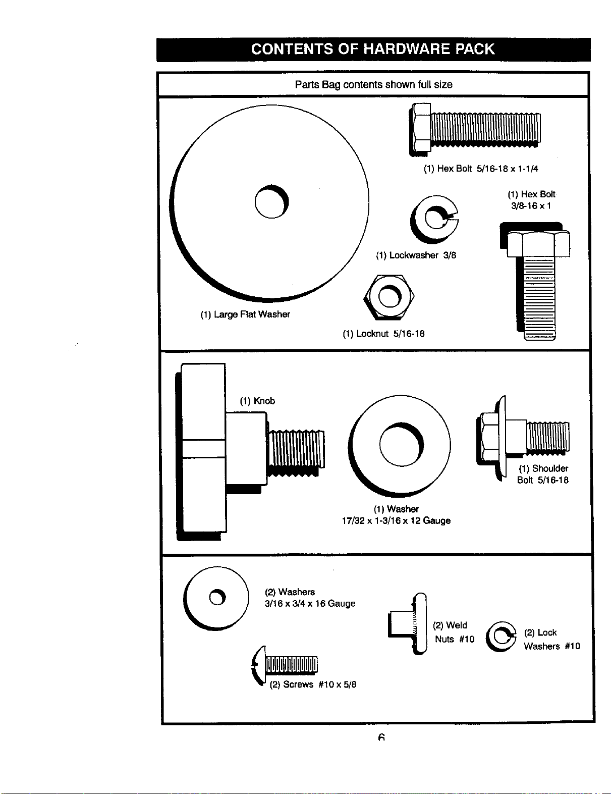
Parts Bag contents shown full size
(1) Hex Bolt 5/16-18 x 1-1/4
(1) Hex Bolt
3/8-16 x 1
(1) Lockwasher 3/8
(1) Large Flat Washer
(1) Locknut 5/16-18
(1) Knob
(1) Washer
17/32x 1-3/16 x 12 Gauge
(1) Shoulder
Bolt 5/16-18
(2) Washers
3/16 x 3/4 x 16 Gauge
__ #10 x 5/8
(2)Weld
Nuts #10
(2) Lock
Washers #10
R
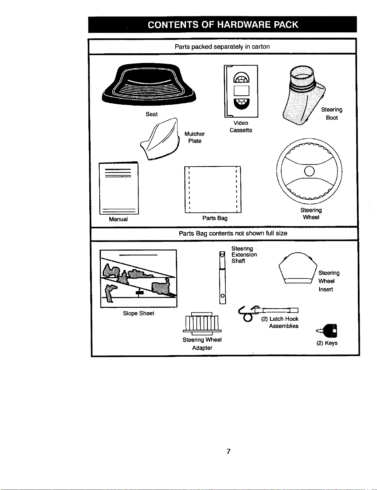
Parts packed separately in carton
Seat
Mulcher
Plate
F-7
Video
Cassette
Steering
Boot
m
Manual
Slope Sheet
ii "
I
I
I
I
I
I
I
I
Parts Bag
Steering
Wheel
Parts Bag contents not shown full size
Steering Wheel
Adapter
Steering
Extension
Shaft
_ Sth:r_g
Insert
.._1 I i
(2) Latch Hook
Assemblies
<4B
(2) Keys
7
Your new tractor has been assembled at the factory with exception of those parts left
unassembled for shipping purposes. To ensure safe and proper operation of your trac-
tor all parts and hardware you assemble must be tightened securely. Use the correct
tools as necessary to insure proper tightness. Review the video cassette before you
begin.
TOOLS REQUIRED FOR ASSEMBLY
A socket wrench set wilt make assembly
easier. Standard wrench sizes you need
are listed below.
(1) 9/16" wrench (1) 3/4" Socket w/
(2) 1/2" wrench drive ratchet
(1) Utility knife (1) Phillips Screw-
(1) Tire pressure gauge driver
When right or left hand is mentioned in
this manual, it means, from your point of
view, when you are in the operating posi-
tion (seated behind the steering wheel).
TO REMOVETRACTOR FROM
CARTON
UNPACK CARTON
• Remove all accessible loose parts and
parts boxes from shipping carton.
• Cut, from top to bottom, along lines on
all four corners of shipping carton, and
lay panels flat.
• Check for any additional loose parts or
boxes and remove.
BEFORE ROLLING TRACTOR OFF
SKID
ATTACH STEERING WHEEL
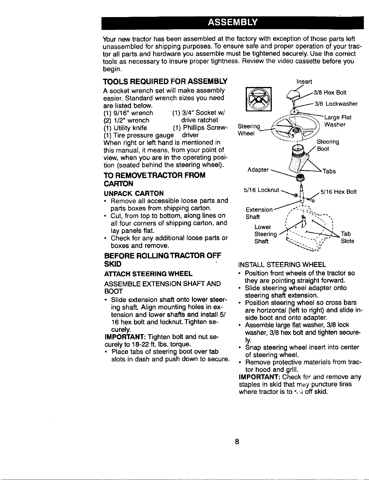
ASSEMBLE EXTENSION SHAFT AND
BOOT
• Slide extension shaft onto lower steer-
ing shaft. Align mounting holes in ex-
tension and lower shafts and install 5/
16 hex bolt and Iocknut. Tighten se-
curely.
IMPORTANT: Tighten bolt and nut se-
curely to 18-22 ft. Ibs. torque.
• Place tabs of steering boot over tab
slots in dash and push down to secure.
Insert
__3/8 Hex Bott
I_ _ 3/8 Lockwasher
_Large Flat
Steering_N--.. _ 1 Washer
Wheel _Steering
Adapter _..._'_..J-'----_ Tab s
Hex Bolt
Tab
Slots
INSTALL STEERING WHEEL
• Position front wheels of the tractor so
they are pointing straight forward.
• Slide steering wheel adapter onto
steering shaft extension.
• Position steering wheel so cross bars
are horizontal (left to right) and slide in-
side boot and onto adapter.
• Assemble large flat washer, 3/8 lock
washer, 3/8 hex bolt and tighten secure-
ly.
• Snap steering wheel insert into center
of steering wheel.
Remove protective materials from trac-
tor hood and grill.
IMPORTANT: Check for and remove any
staples in skid that may puncture tires
where tractor is to ",.;i off skid.
8
HOWTO SET UPYOURTRACTOR
CHECK BA'I-I'ERY
• Lift seat pan to raised position and
open battery box door.
• If this battery is put into service after
month and year indicated on label (la-
bel located between terminals) charge
battery for minimum of one hour at 6-10
amps. (See "BATTERY" in MAINTE-
NANCE section of this manual for
charging instructions).
Seat
Pan
Bakery
Box
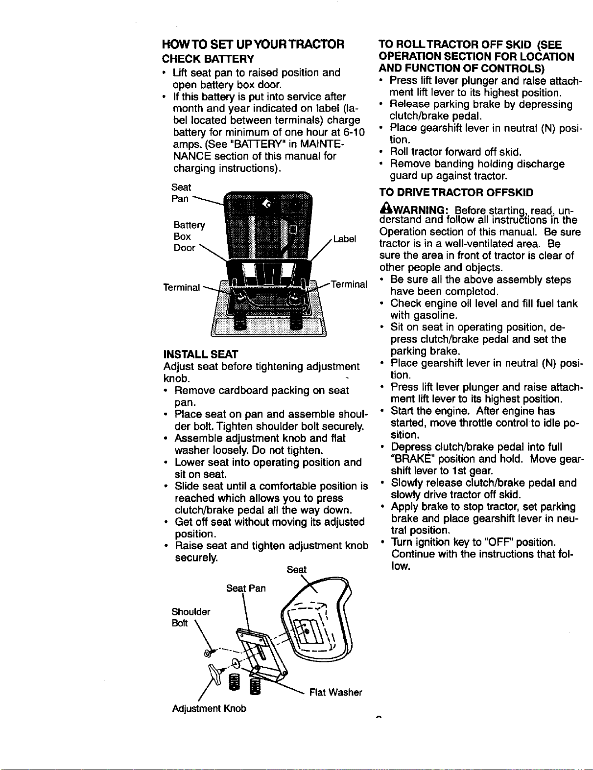
INSTALL SEAT
Adjust seat before tightening adjustment
knob.
• Remove cardboard packing on seat
pan.
• Place seat on pan and assemble shoul-
der bolt.Tighten shoulder bolt securely.
• Assemble adjustment knob and flat
washer loosely. Do not tighten.
• Lower seat into operating position and
sit on seat.
• Slide seat until a comfortable position is
reached which allows you to press
clutch/brake pedal all the way down.
• Get off seat without moving itsadjusted
position.
• Raise seat and tighten adjustment knob
securely.
Seat
Seat Pan
Shoulder
Bolt _ ....
TO ROLLTRACTOR OFF SKID (SEE
OPERATION SECTION FOR LOCATION
AND FUNCTION OF CONTROLS)
• Press lift lever plunger and raise attach-
ment lift lever to its highest position.
• Release parking brake by depressing
clutch/brake pedal,
• Place gearshift lever in neutral (N) posi-
tion.
• Roll tractor forward off skid.
• Remove banding holding discharge
guard up against tractor.
TO DRIVE TRACTOR OFFSKID
_brWAR,NING: Before starting, read, un-
s[ana and follow all instructions in the
Operation section of this manual. Be sure
tractor is in a well-ventilated area. Be
sure the area in front of tractor is clear of
other people and objects.
• Be sure all the above assembly steps
have been completed.
• Check engine oil level and fill fuel tank
with gasoline.
• Sit on seat in operating position, de-
press clutch/brake pedal and set the
parking brake.
• Place gearshift lever in neutral (N) posi-
tion.
• Press lift lever plunger and raise attach-
ment lift lever to its highest position.
• Start the engine. After engine has
started, move throttle control to idle po-
sition.
• Depress clutch/brake pedal into full
"BRAKE" position and hold. Move gear-
shift lever to 1st gear.
• Slowly release clutch/brake pedal and
slowly drive tractor off skid.
• Apply brake to stop tractor, set parking
brake and place gearshift lever in neu-
tral position.
• Turn ignition key to "OFF" position.
Continue with the instructions that fol-
lOW.
Flat Washer
Adjustment Knob
CHECKTIRE PRESSURE
Thetiresonyourtractorwereoverinflated
atthefactoryfor shippingpurposes.Cor-
recttirepressureisimportantfor bestcut-
ting performance.
• Reducetirepressureto PSIshownin
"PRODUCT SPECIFICATIONS" section
of this manual.
CHECK DECK LEVELNESS
For best cutting results, mower housing
should be properly leveled. See 'q-O
LEVEL MOWER HOUSING" in the Ser-
vice and Adjustments section of this
manual.
CHECK FOR PROPER POSITION OF
ALL BELTS
See the figures that are shown for replac-
ing motion and mower blade drive belts
in the Service and Adjustments sectoin of
this manual. Verify that the bc',ts are
routed correctly.
CHECK BRAKE SYSTEM
After you learn how to operate your trac-
tor, check to see that the brake is properly
adjusted. See "TO ADJUST BRAKE" in
the Service and Adjustments section of
this manual.
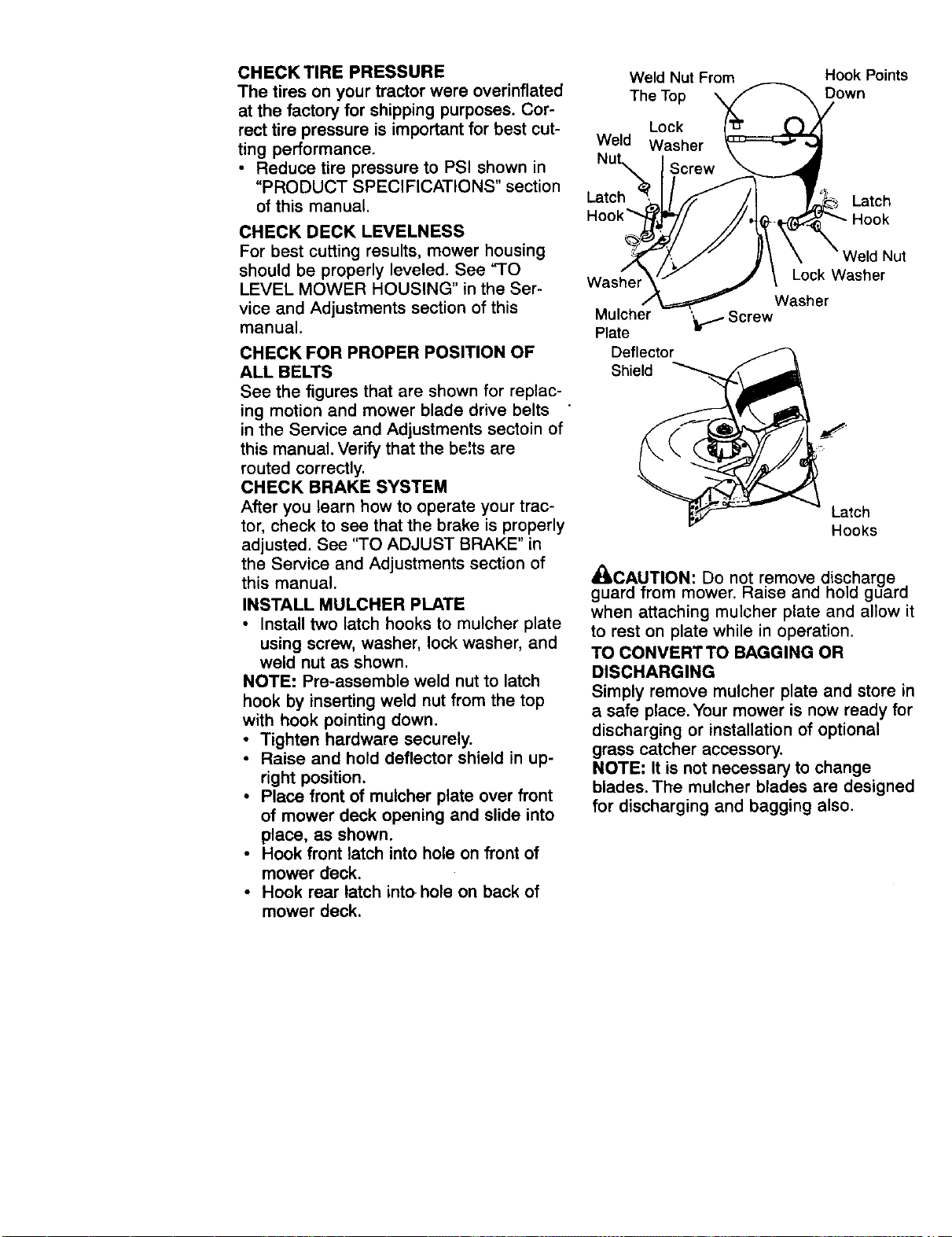
INSTALL MULCHER PLATE
• Install two latch hooks to mulcher plate
using screw, washer, lock washer, and
weld nut as shown.
NOTE: Pre-assemble weld nut to latch
hook by inserting weld nut from the top
with hook pointing down.
• Tighten hardware securely.
• Raise and hold deflector shield in up-
right position.
• Place front of mulcher plate over front
of mower deck opening and slide into
place, as shown.
• Hook front latch into hole on front of
mower deck.
• Hook rear latch into hole on back of
mower deck.
Weld Nut From Hook Points
The Top Down
Lock
Weld Washer
Latch Latch
Hook
Washer
Mulcher
Plate
Deflector
Shield
Weld Nut
Lock Washer
Washer
'_ir.1 Screw
Latch
Hooks
_I, CAUTION: Do no..ttremove discharge .
guard from mower. _aise and hold guara
when attaching mulcher plate and allow it
to rest on plate while in operation.
TO CONVERTTO BAGGING OR
DISCHARGING
Simply remove mulcher plate and store in
a safe place. Your mower is now ready for
discharging or installation of optional
grass catcher accessory.
NOTE: It is not necessary to change
blades. The mulcher blades are designed
for discharging and bagging also.
•F CHECKLIST
Before you operate and enjoy your new
tractor, we wish to assure that you receive
the best performance and satisfaction
from this Quality Product.
Please review the following checklist:
_/All assembly instructions have been
completed.
J No remaining loose parts in carton.
,/Battery is properly prepared and
charged. (Minimum 1 hour at 6 amps).
4' Seat is adjusted comfortably and tight-
ened securely.
,/All tires are properly inflated. (For ship-
ping purposes, the tires were overin-
flated at the factory).
,/Be sure mower deck is properly leveled
side-to-side/front-to-rear for best cutting
results. (Tires must be properly inflated
for leveling).
,/Check mower and drive belts. Be sure
they are routed properly around pulleys
and inside all belt keepers.
,/Check wiring. See that all connections
are still secure and wires are properly
clamped.
WHILE LEARNING HOW TO USE YOUR
TRACTOR, PAY EXTRA AI-I'ENTION TO
THE FOLLOWING IMPORTANT ITEMS:
/ Engine oil is at proper level.
,/Fuel tank is filled with fresh, clean,
regular unleaded gasoline.
•/ Become familiar with all controls - their
location and function. Operate them be-
fore you start the engine.
/ Be sure brake system is in safe operat-
ing condition.
• 11
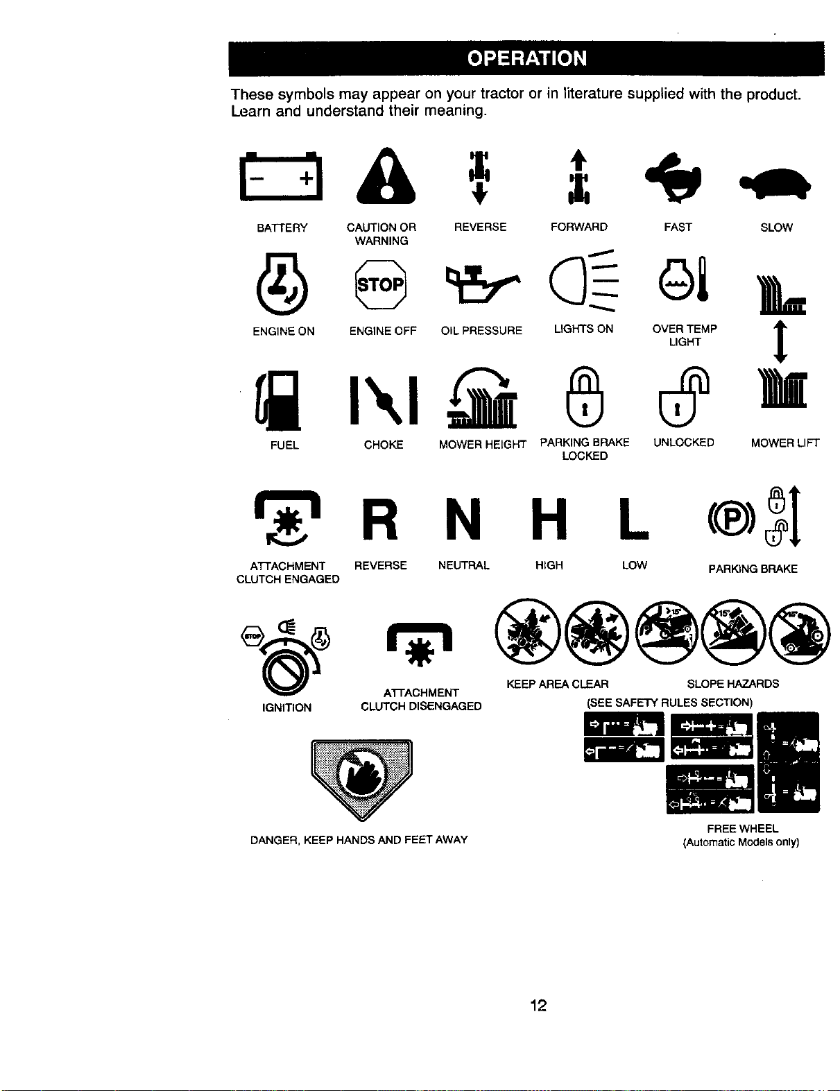
These symbols may appear on your tractor or in literature supplied with the product.
Learn and understand their meaning.
BATTERY CAUTION OR REVERSE FORWARD FAST SLOW
WARNING
A
ENGINE ON ENGINE OFF OIL PRESSURE OGHTS ON OVER TEMP 1P
LIGHT
FUEL CHOKE MOWER HEIGHT PARKING BRAKE UNLOCKED MOWER LIFT
LOCKED
R N H L
ATTACHMENT REVERSE NEUTRAL HIGH LOW PARKING BRAKE
CLUTCH ENGAGED
(_ _ KEEP AREA CLEAR SLOPE HAZARDS
ATFACHMENT
IGNITION CLUTCH DISENGAGED
DANGER, KEEP HANDS AND FEET AWAY
(SEE SAFETY RULES SECTION)
FREE WHEEL
(Automatic Models only)
12
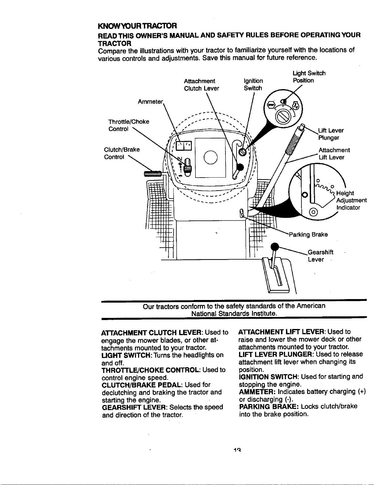
KNOWYOUR TRACTOR
READ THIS OWNER'S MANUAL AND SAFETY RULES BEFORE OPERATING YOUR
TRACTOR
Compare the illustrations with your tractor to familiarize yourself with the locations of
various controls and adjustments. Save this manual for future reference.
Attachment Ignition
Clutch Lever Switch
Ught Switch
Position
s
Throttle/Choke ." ."
Control
Clutch/Brake
Control
Uft Lever
Plunger
Attachment
Lever
Height
ustment
Indicator
'Parking Brake
Our tractors conform to the safety standards of the American
National Standards Institute.
ATTACHMENT CLUTCH LEVER: Used to
engage the mower blades, or other at-
tachments mounted to your tractor.
LIGHT SWITCH: Turns the headlights on
and off.
THRO'I'rLE/CHOKE CONTROL: Used to
control engine speed.
CLUTCH/BRAKE PEDAL: Used for
declutching and braking the tractor and
starting the engine.
GEARSHIFT LEVER: Selects the speed
and direction of the tractor.
ATTACHMENT LIFT LEVER: Used to
raise and lower the mower deck or other
attachments mounted to your tractor.
LIFT LEVER PLUNGER: Used to release
attachment lift lever when changing its
position.
IGNITION SWITCH: Used for starting and
stopping the engine.
AMMETER: Indicates battery charging (+)
or discharging (-).
PARKING BRAKE: Locks clutch/brake
into the brake position.
The operation of any tractor can result in foreign objects thrown intothe
eyes, which can result in severe eye damage. Always wear safety glasses
or eye shields while operating your tractor or performing any adjustments
or repairs. We recommend a wide vision safety mask over spectacles, or
standard safety glasses.
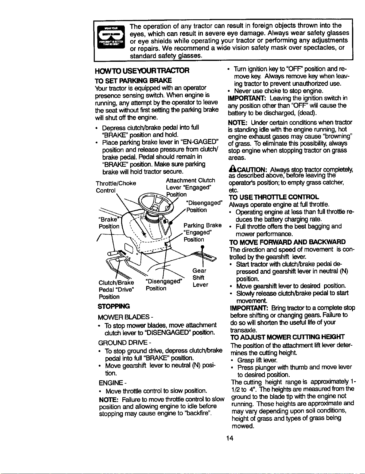
HOWTO USEYOURTRACTOR
TO SET PARKING BRAKE
Yourtractorisequippedwithan operator
presence sensingswitch.When engine is
running,any attemptbythe operatortoleave
the seat withoutfirstsettingthe parkingbrake
willshutoffthe engine.
• Depress clutch/brake pedal intofull
"BRAK]E" position and hold.
• Place perking brake lever in "EN-GAGED"
pos_on and release pressure from clutch/
brake pedal. Pedal should remain in
"BRAKE" position. Make sure parking
brake will hold tractor secure.
Throttle/Choke
Control
Attachment Clutch
Lever "Engaged"
Position
"Disengaged"
ition
Position Parking Brake
ed"
Position
Clutch/Brake "Disengaged"
Pedal "Drive" Position
Position
STOPPING
Gear
Shift
Lever
MOWER BLADES -
• To stop mower blades, move attachment
dutch lever to "DISENGAGED" position.
GROUND DRIVE -
• To stop ground drive, depress dutch/brake
pedal into full "BRAKE" position.
• Move gearshift lever to neutral (N) posi-
tion.
ENGINE -
Move throttle control to slow position.
NOTE: Failure to move throtlle control to slow
position and allowing engine to idle before
stopping may cause engine to "backfire".
• Turn ignition key to "OFF" positionand re-
move key. Always remove key when leav-
ing tractor to prevent unauthorized use.
• Never use choke to stop engine.
IMPORTANT: Leaving the ignition switch in
any position other than "OFF' will cause the
battery to be discharged, (dead).
NOTE: Under certain conditions when tractor
is standing idle with the engine running, hot
engine exhaust gases may cause "browning"
of grass. To eliminate this possibility,always
stop engine when stopping tractor on grass
areas.
_CAUTION: Always stop .'_'actorco,mpletely,
as described above, before leaving me
operator's position;to empty grass catcher,
etc.
TO USETHROTrl_E CONTROL
Always operate engine at full throttle.
• Operating engine at less than full throttle re-
duces the battery charging rate.
• Full thro_e offers the bast bagging and
mower performance.
TO MOVE FORWARD AND BACKWARD
The direction and speed of movement is cen-
trolledby thegearshiftlever.
• Start tractor with dutch/brake pedal de-
pressed and gearshift lever in neutral (N)
position.
• Move gearshift lever to desired position.
• Slowly release clutch/brake pedal to start
movement.
IMPORTANT: Bring tractor to a complete stop
before shifting or changing gears. Failure to
do so will shorten the useful life of your
transaxle.
TO ADJUST MOWER CUTTING HEIGHT
The position of the attachment liftlever deter-
mines the cutting height.
• Grasp lift lever.
• Press plunger with thumb and move lever
to desired position.
The cutting height range is approximately 1-
1/2 to 4". The heights are measured from the
ground to the blade tip with the engine not
running. These heights are approximate and
may vary depending upon soil conditions,
height of grass and types of grass being
mowed.
14
• The average lawn should be cut to ap-
proximately 2-1/2 inches during the cool
season and to over 3 inches during hot
months. For healthier and better looking
lawns, mow often and alter moderate
growth.
• For best cutting performance, grass over 6
inches in height should be mowed twice.
Make the first cut relatively high; the sec-
ond to desired height.
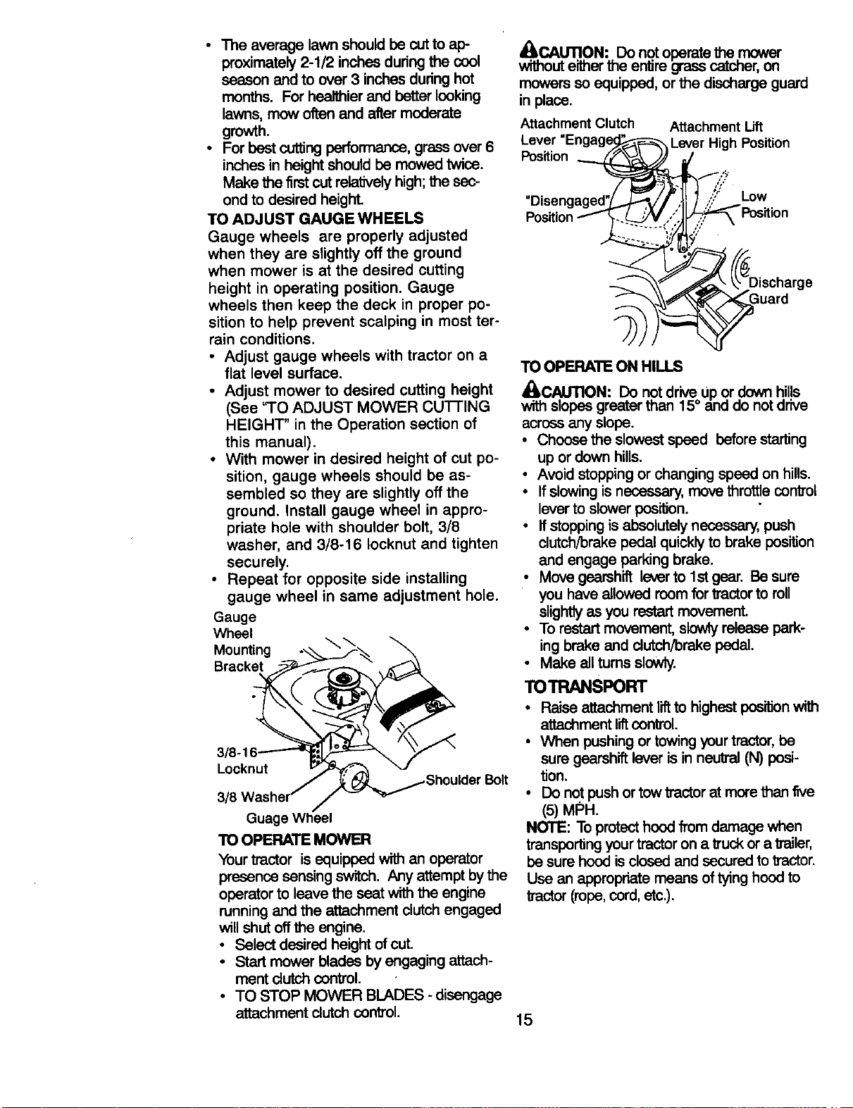
TO ADJUST GAUGE WHEELS
Gauge wheels are properly adjusted
when they are slightly off the ground
when mower is at the desired cutting
height in operating position. Gauge
wheels then keep the deck in proper po-
sition to help prevent scalping in most ter-
rain conditions.
• Adjust gauge wheels with tractor on a
flat level surface.
• Adjust mower to desired cutting height
(See '3"0 ADJUST MOWER CU'I-rlNG
HEIGHT" in the Operation section of
this manual).
• With mower in desired height of cut po-
sition, gauge wheels should be as-
sembled so they are slightly off the
ground. Install gauge wheel in appro-
priate hole with shoulder bolt, 3/8
washer, and 3/8-16 Iocknut and tighten
securely.
• Repeat for opposite side installing
gauge wheel in same adjustment hole.
Gauge
Wheel
Mounting
Bracket
Locknut
Guage Wheel
TO OPERATE MOWER
Your tractor is equipped with an operator
presence sensing switch. Any attempt by the
operator to leave the seat with the engine
running and the attachment clutch engaged
will shut off the engine.
• Select desired height of cut.
• Start mower blades by engaging attach-
ment clutch control.
• TO STOP MOWER BLADES - disengage
attachment clutch control.
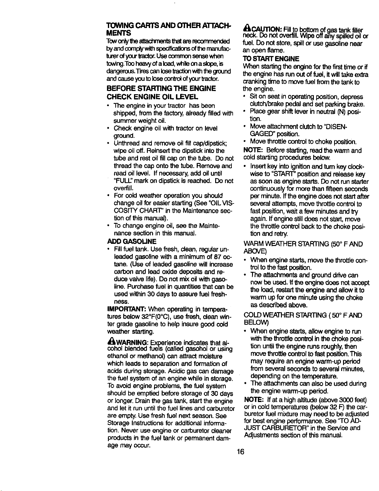
_.. CAUTI.ON:.Do notoperatethe mower
withouteitherme entiregrasscatcher,on
mowersso equipped,or the dischargeguard
in place.
Attachment Clutch
Lever
Position
Attachment Lift
Lever High Position
"Disen
Position
LOW
TO OPERATE ON HILLS
_iLCAUTION: Do notdriveUpor downhills
withslopesgreaterthan 15° and do notdrive
across anyslope.
• Choosethe slowestspeed beforestarting
up ordownhills.
• Avoid stopping orchangingspeed on hills.
• Ifslowingis necessary,movethrottle control
leverto slowerposition.
• Ifstoppingisabsolutelynecessary,push
clutch/brakepedalquicklyto brake position
and engage parkingbrake.
• Move gearshiftleverto lst gear. Besure
you haveallowedroomfor tractortoroll
slightlyasyou restartmovement.
• To restartmovement,slowlyreleasepark-
ingbrake and clutch/brakepedal.
• Make all turnsslowly.
TOTRANSPORT
• Raise attachmentli_ to highest position with
attachmentliftcontrol.
• When pushingortowingyourtractor,be
suregearshiftleverisin neutral(N) posi-
tion.
• Do notpushortowtractorat merethan five
(5) MPH.
NOTE: Toprotecthoodfromdamage when
transportingyourtractorona truckora trailer,
besure hoodisdosed and securedtotractor.
Use an appropriatemeans of tyinghoodto
tractor(rope,cord,etc.).
15
TOWING CARTS AND OTHER A'rrACH.
MENTS
Towonlythe atiachmentsthatare recommended
byandcom_ w_ spec_a_nsofthemanofac-
tutorofyour_'actor.Use common sensewhen
towing.Tooheavyof a Icad,whileona slope,is
dangerous._res canlosetractionwiththeground
and cause you to lose control of your tractor.
BEFORE STARTING THE ENGINE
CHECK ENGINE OIL LEVEL
• The engine in your tractor has been
shipped, from the factory, already filled with
summer weight oil.
• Check engine oil with tractor on level
ground.
• Unthread and remove oil fill cap/dipstick;
wipe oil off. Reinsert the dipstick into the
tube and rest oil fillcap on the tube. Do not
thread the cap onto the tube. Remove and
read oil level. If necessary, add oil until
"FULL' mark on dipstick is reached. Do not
overfill.
• For cold weather operation you should
change oil for easier starting (See "OIL VIS-
cosrrY CHART" in the Maintenance sec-
tion of this manual).
• To change engine oil, see the Mainte-
nanca section in this manual.
ADD GASOLINE
• Fill fuel tank. Use fresh, clean, regular un-
leaded gasoline with a minimum of 87 oc-
tane. (Use of leaded gasoline will increase
carbon and lead oxide deposits and re-
duce valve life). Do not mix oil w_ gaso-
line. Purchase fuel in quantities that can be
used within 30 days to assure fuel fresh-
ness.
IMPORTANT: When operating in tempera-
tures below 32°F(0°C), use fresh, clean win-
ter grade gasoline to help insure good cold
weather starting.
_WARNING: Experience indicates that al-
cohol blended fuels (called gasohol or using
ethanol or methanol) can attract moisture
which leeds to separation and formation of
acids during storage. Acidic gas can damage
the fuel system of an engine while in storage.
To avoid engine problems, the fuel system
should be emptied before storage of 30 days
or longer. Drain the gas tank, start the engine
and let it run until the fuel lines and carburetor
are empty. Use fresh fuel next season. See
Storage Instructions for additional informa-
tion. Never use engine or carburetor cleaner
products in the fuel tank or permanent dam-
age may occur.
_CAUTION: Fillto bottom of gas tank filler
neck. Do not overfill. Wipe offany spilled oil or
fuel. Do not store, spill or use gasoline near
an open flame.
TO START ENGINE
When starting the engine for the firsttime or if
the engine has run out of fuel, it will take extra
cranking time to move fuel from the tank to
the engine.
• Sit on seat in operating position, depress
clutch/brake pedal and set parking brake.
• Place gear shift lever in neutral (N) posi-
tion.
• Move attachment clutch to "DISEN-
GAGED" position.
• Move throttle control to choke position.
NOTE: Before starting, read the warm and
cold starting procedures below.
• Insert key into ignition and turn key clock-
wise to "START" position and release key
as soon as engine starts. Do not run starter
continuously for more than fifteen seconds
per minute, ff the engine does not start after
several attempts, move throttle control to
fast position, wait a few minutes and try
again. Ifengine stilldoes not start, move
the throttle control back to the choke posi-
tion and retry.
WARM WEATHER STARTING (50° F AND
ABOVE
• When engine starts, move the throttle con-
trol to the fast position.
• The attachments and ground drive can
now be used. If the engine does not accept
the load, restart the engine and allow it to
warm up for one minute using the choke
as described above.
COLD WEATHER STARTING ( 50oF AND
BELOW)
• When enginestarts,allow enginetorun
withthe throttle control in the choke posi-
tion until the enginerunsroughly,then
movethrottle controlto fast position.This
may requirean enginewarm-up peried
fromseveralsecondsto severalminutes,
dependingonthe temperature.
• The attachmentscanalsobe usedduring
the enginewarm-up period.
NOTE: Ifat a highaltitude(above3000 feet)
or incold temperatures(below32 F) the car-
buretorfuel mixturemay needto be adjusted
for best engine performance. See 'TO AD-
JUST CARBURETOR" in the Service and
Adjustments section of this manual.
16
MOWING'rIPS
• Mower shouldbe properlyleveledfor best
mowing performance.See "TO LEVEL
MOWER HOUSING" intheServiceand
Adjustments sectionof this manual.
• The left hand side of mower should be
used for trimming.
• Drive so that clippingsare discharged onto
the areathat has been cut. Have the cut
area to the right of the tractor.This will result
in a more even distribution of clippings and
more uniform cutting.
• When mowing large areas, start by tuming
to the rightso that clippings will discharge
away from shrubs, fences, driveways, etc.
Al_erone or two rounds, mow in the oppo-
site direction making left hand turns until
finished.
* If grass is extremely tall, itshould be
mowed twice to reduce load and possible
firehazard from dried clippings. Make first
cut relatively high; the second to thede-
siredheight.
• Do not mow grass when itis wet. Wet
grass will plug mower and leave undesir-
able clumps. Allow grass to dry before
mowing.
• Always operate engine at full throttle
when rnowing toassurebetter mowing,
performanceand properdischargeof ma-
terial.Regulategroundspeed by selecting
a low enough gearto givethe mowerthe
bestcuttingperformance as well as the
quality of cut desired.
• When operatingattachments, selecta
groundspeed that will suitthe terrainand
give bestperformance ofthe attachment
being used.
1
MULCHING MOWING TIPS
IMPORTANT: For best performance, keep
mower housing free of built-up grass and
trash. Clean after each use.
• The special mulching blade will recut the
grass clippings many times and reduce
them in size so that as they fall onto the
lawn they will disperse into the grass and
not be noticed. Also, the mulched grass will
biodegrade quickly to provide nutrients for
the lawn. Always mulch with your highest
engine (blade) speed as this will provide
the best recurring action of the blades.
• Avoid cuUJngyour lawn when itis wet. Wet
grass tends to form clumps and interferes
with the mulching action. The best time to
mow your lawn is the early aftemoon. At
this time the grass has dried and the newly
cut area will not be exposed to the direct
sun.
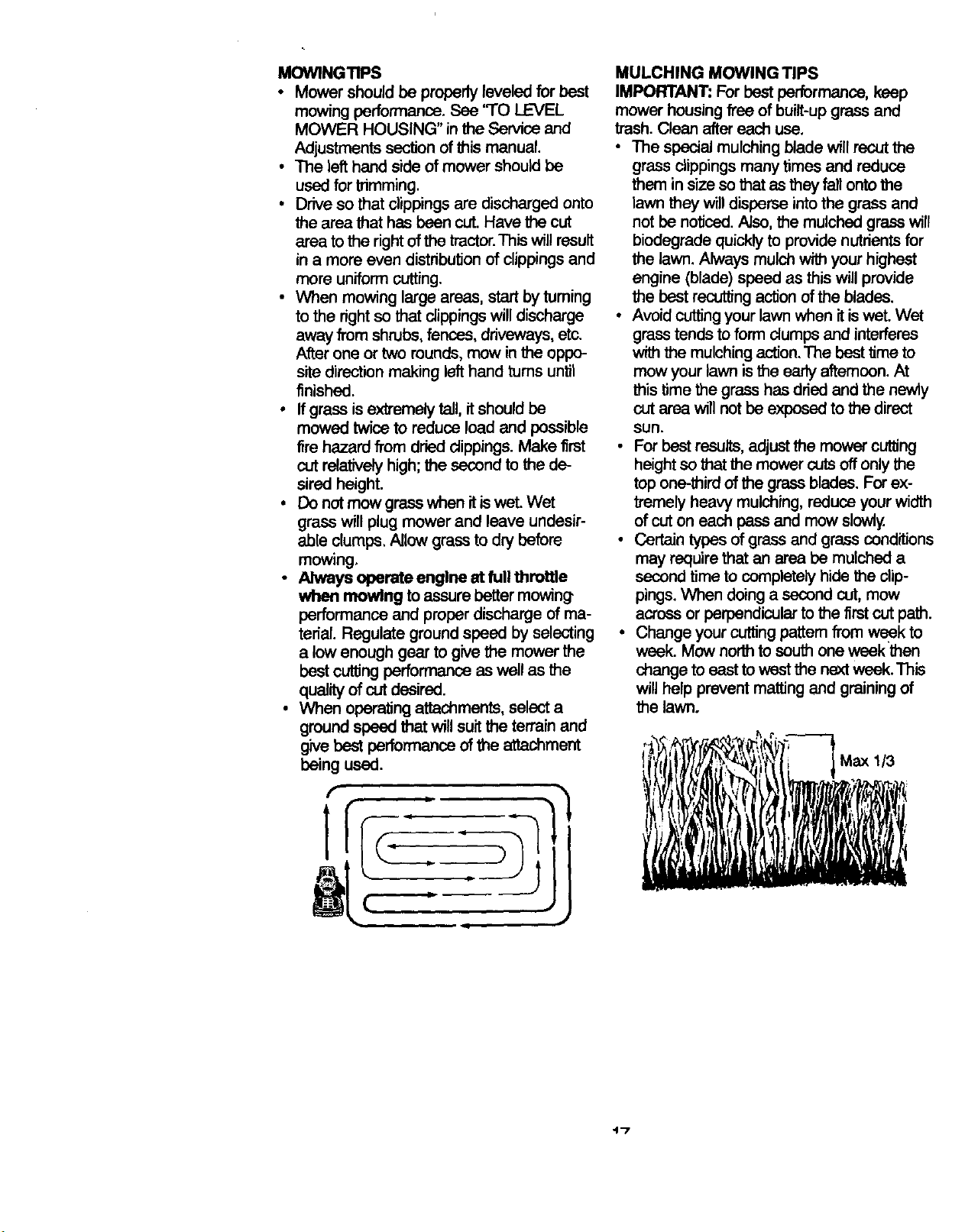
• For best results, adjust the mower cutting
height so that the mower cuts off only the
top one-third of the grass blades. For ex-
b'emely heavy mulching, reduce your width
of cut on each pass and mow slowly.
• Certain types of grass and grass conditions
may require that an area be mulched a
second time to completely hide the clip-
pings. When doing a second cut, mow
across or perpendicular to the first cut path.
• Change your cutting pattern from week to
week. Mow north to south one week then
change to east to west the next weak. This
will help prevent matting and graining of
the lawn.
Max 1/3
"1"7
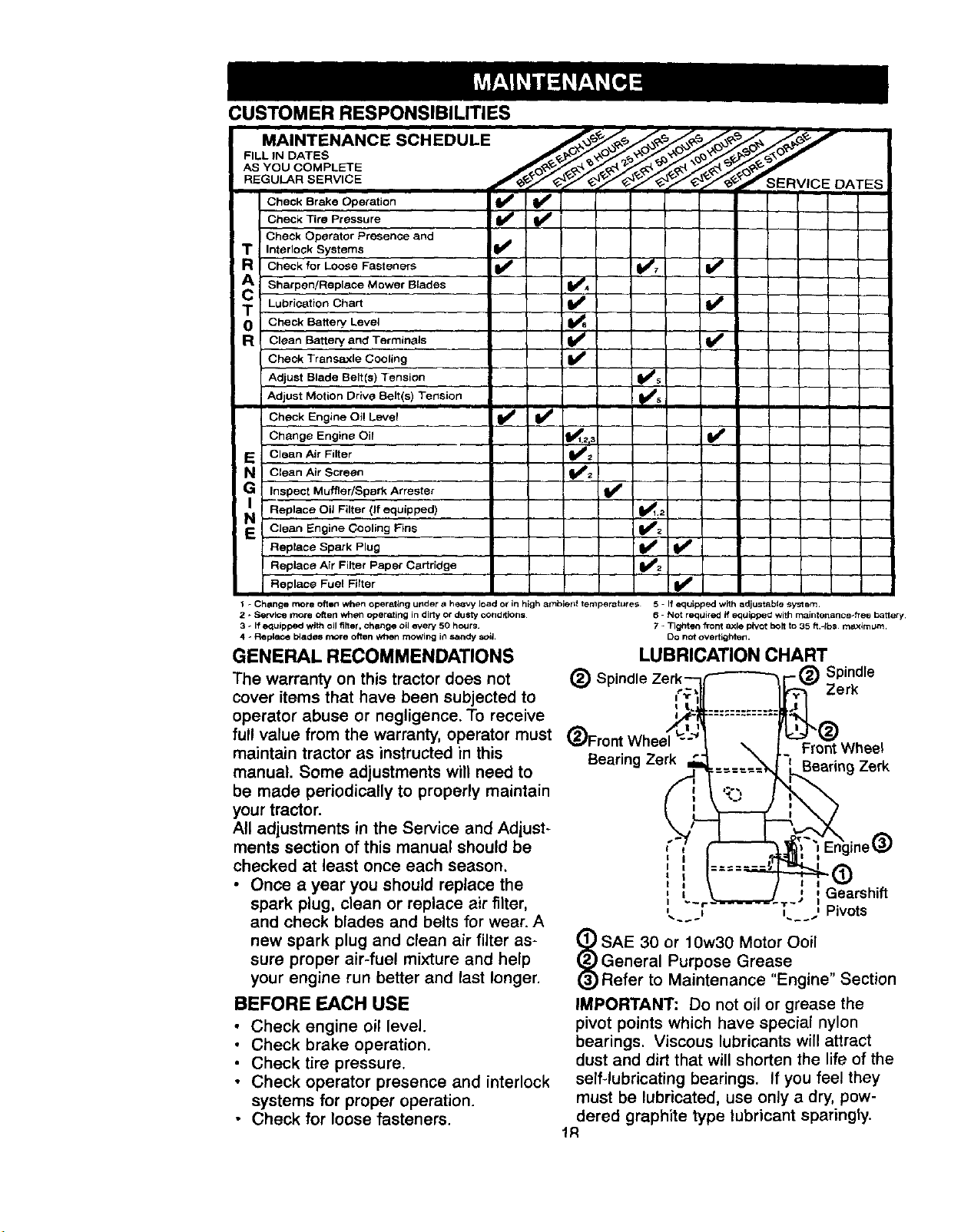
CUSTOMER RESPONSIBILITIES
FILL IN DATES /___k-_O/_n_o'_y./_'_'F_/_@J
AS YOU COMPLETE ,_,_ R.__ R.j_ .j_j_ _% _cj_
REGULAR SERVICE J___ _ SERV,CE DATES
CheokOrakoOpe,ation
Check Tire Pressure
Check Operator Presence and
T InterloCk Systems
a Check for Loose Fasteners
A Sharpen/Replace Mower Blades _4
T Lubrication Chart
0 Check Battery. Level
R Clean Battery and Termin_Js
Check Transaxle Cooling
Adjust Blade Belt(s) Tension
! Adjust Motion Drive Belt(s) Tension
Check Engine Oi! Level
Change Engine Oil
E Clean Air Filter
a Clean Air Screen
Inspect Muffler/Spark Arrester
Replace OiJ Filter (If equipped)
NE CJean Engine Cooling Fins
Replace Spark Plug
Replace Air Filter Paper Cartridge
Replace Fuel Filter
v'
v' v'
I v'
v'
_2
I - Chenge more often when operating under a hesvy load o_ in high ambietd temper_tufe_ 5 - If equipped with adjustable sy_em.
2 * Service more often when operating in dirty or dusty cOndetions
3 _ If equipped with oil filter, che=nge oil every 50 hours¸
4 _ Re placG I_ades more ohen when mowing ir_Sandy soil
GENERAL RECOMMENDATIONS
The warranty on this tractor does not
cover items that have been subjected to
operator abuse or negligence. To receive
full value from the warranty, operator must
maintain tractor as instructed in this
manual. Some adjustments will need to
be made periodically to properly maintain
your tractor.
All adjustments in the Service and Adjust-
ments section of this manual should be
checked at least once each season.
• Once a year you should replace the
spark plug, clean or replace air filter,
and check blades and belts for wear. A
new spark plug and clean air filter as-
sure proper air-fuel mixture and help
your engine run better and last longer.
BEFORE EACH USE
• Check engine oil level.
• Check brake operation.
• Check tire pressure.
• Check operator presence and interlock
systems for proper operation.
• Check for loose fasteners.
@
6 Not r_quired if equipped with rnaintenance_fTee batlery
7 - 71ghten front axle pivot bolt to 35 ft.-Ibs m_aximum.
Do not overtighten.
LUBRICATION CHART
Spindle
Zerk
Front Wheel
Bearing Zerk Bearing Zerk
f" ine(_)
t I
-d)
a i _ , Pivots
SAE 30 or 10w30 Motor O0il
General Purpose Grease ,
Refer to Maintenance "Engine' Section
IMPORTANT: Do not oil or grease the
pivot points which have special nylon
bearings. Viscous lubricants will attract
dust and dirt that will shorten the life of the
self-lubricating bearings. If you feel they
must be lubricated, use only a dry, pow-
dered graphite type lubricant sparingly.
TRACTOR
Always observe safety rules when per-
formingany maintenance.
BRAKE OPERATION
If tractor requires more than six (6) feet
stopping distance at high speed in high-
est gear, then brake must be adjusted.
(See 'TO ADJUST BRAKE" in the Service
and Adjustments section of this manual).
TIRES
• Maintain proper air pressure in all tires
(See "PRODUCT SPECiFiCATiONS"
section of this manual).
• Keep tires free of gasoline, oil, or insect
control chemicals which can harm rub-
ber.
• Avoid stumps, stones, deep ruts, sharp
objects and other hazards that may
cause tire damage.
NOTE: To seal tire punctures and prevent
flat tires due to slow leaks, tire sealant
may be purchased from your local parts
dealer. Tire sealant also prevents tire dry
rot and corrosion.
OPERATOR PRESENCE SYSTEM
Be sure that operator presence and inter-
lock systems are working properly. If your
tractor does not function as described be-
low, repair the problem immediately.
• The engine should not start unless the
clutch/brake pedal is fully depressed
and attachment clutch control is in the
disengaged position.
• When the engine is running, any at-
tempt by the operator to leave the seat
without first setting the parking brake
should shut off the engine.
• When the engine is running and the at-
tachment clutch is engaged, any at-
tempt by the operator to leave the seat
should shut offthe engine.
• The attachment clutch should never op-
erate unless the operator is in the seat.
BLADE CARE
For best results mower blades must be
kept sharp. Replace bent or damaged
blades.
BLADE REMOVAL
• Raise mower to highest position to al-
low access to blades.
• Remove hex bolt, lock washer and flat
washer securing blade.
• Install new or resharpened blade with
trailing edge up towards deck as
shown.
IMPORTANT: To ensure proper assembly,
center hole in blade must align with star
on mandrel assembly.
• Reassemble hex bolt, lock washer and
flat washer in exact order as shown.
• Tighten bolt securely (27-35 Ft. Lbs.
torque).
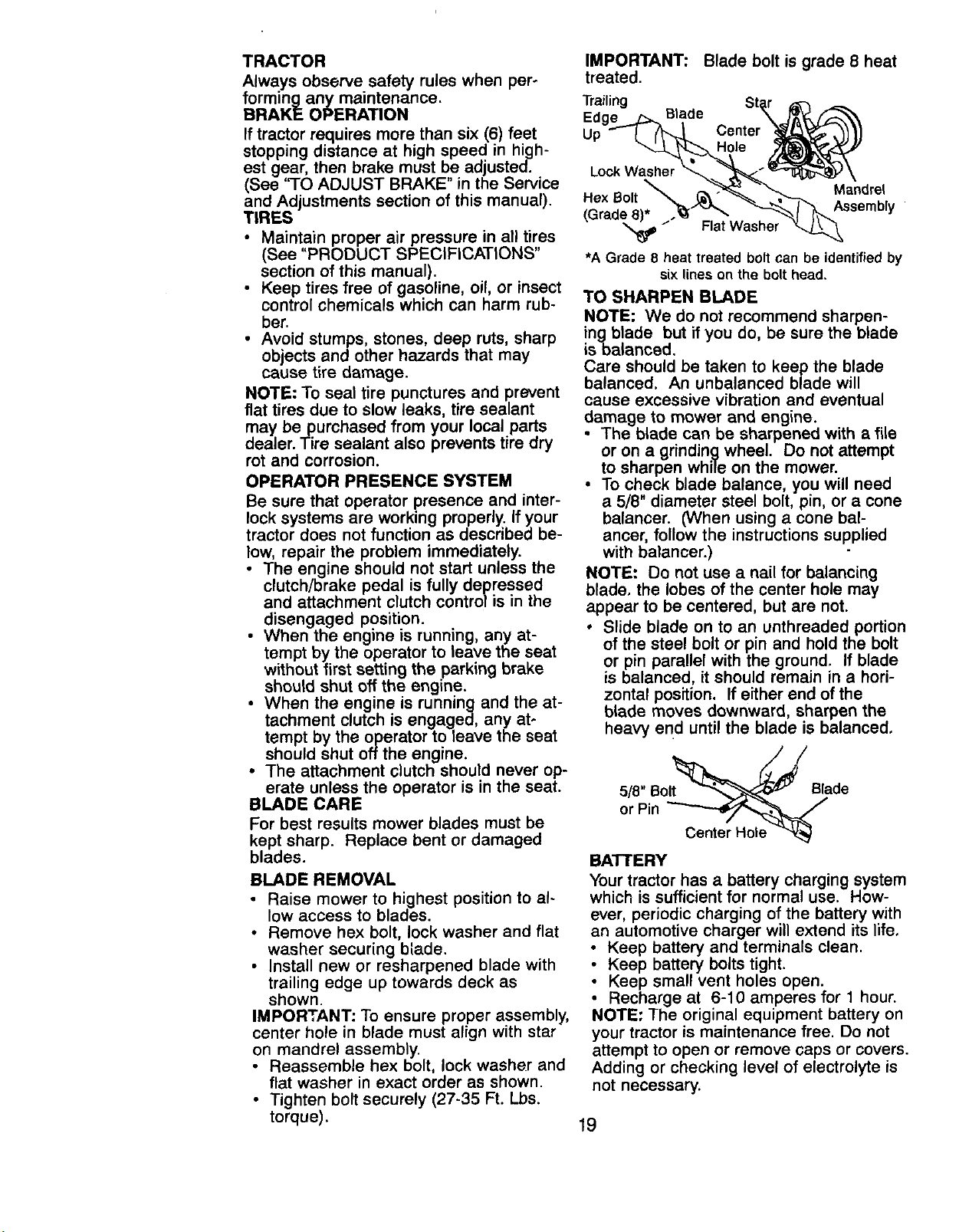
IMPORTANT: Blade bolt is grade 8 heat
treated.
Trailing
Edge Blade
Up
Lock Washer
Mandre{
Assembly
(Grade_ Flat Washer
*A Grade 8 heat treated bolt can be identifiedby
six lines on the bolt head.
TO SHARPEN BLADE
NOTE: We do not recommend sharpen-
ingbtade but if you do, be sure the blade
isbalanced.
Care should be taken to keep the blade
balanced. An unbalanced blade will
cause excessive vibration and eventual
damage to mower and engine.
The blade can be sharpened with a file
or on a grinding wheel. Do not attempt
to sharpen while on the mower.
• To check blade balance, you will need
a 5/8" diameter steel bolt, pin, or a cone
balancer. (When using a cone bal-
ancer, follow the instructions supplied
with balancer.)
NOTE: Do not use a nail for balancing
blade, the lobes of the center hole may
appear to be centered, but are not.
• Slide blade on to an unthreaded portion
of the steel bolt or pin and hold the bolt
or pin parallel with the ground. If blade
is balanced, it should remain in a hori-
zontal position. If either end of the
blade moves downward, sharpen the
heavy end until the blade is balanced.
5/8" Bolt Blade
or Pin
BATTERY
Your tractor has a battery charging system
which is sufficient for normal use. How-
ever, periodic charging of the battery with
an automotive charger will extend its life.
• Keep battery and terminals clean.
Keep battery bolts tight.
Keep small vent holes open.
• Recharge at 6-10 amperes for 1 hour.
NOTE: The original equipment battery on
your tractor is maintenance free. Do not
attempt to open or remove caps or covers.
Adding or checking level of electrolyte is
not necessary.
19
TO CLEAN BATIERY AND TERMINALS
Corrosion and dirt on the battery and ter-
minals can cause the battery to "leak"
power.
• Open battery box door.
• Disconnect BLACK battery cable first
then RED battery cable and remove
battery from tractor.
• Rinse the battery with plain water and
dry.
• Clean terminals and battery cable ends
with wire brush until bright.
• Coat terminals with grease or petro-
leum jelly.
• Reinstall battery (See "REPLACING
BATTERY" in the SERVICE AND AD-
JUSTMENTS section of this manual)•
V-BELTS
Check V-belts for deterioration and wear
after 100 hours of operation and replace
if necessary. The belts are not adjustable.
Replace belts if they begin to slip from
wear.
TRANSAXLE COOLING
Keep transaxle free from build-up of dirt
and chaff which can restrict cooling.
ENGINE
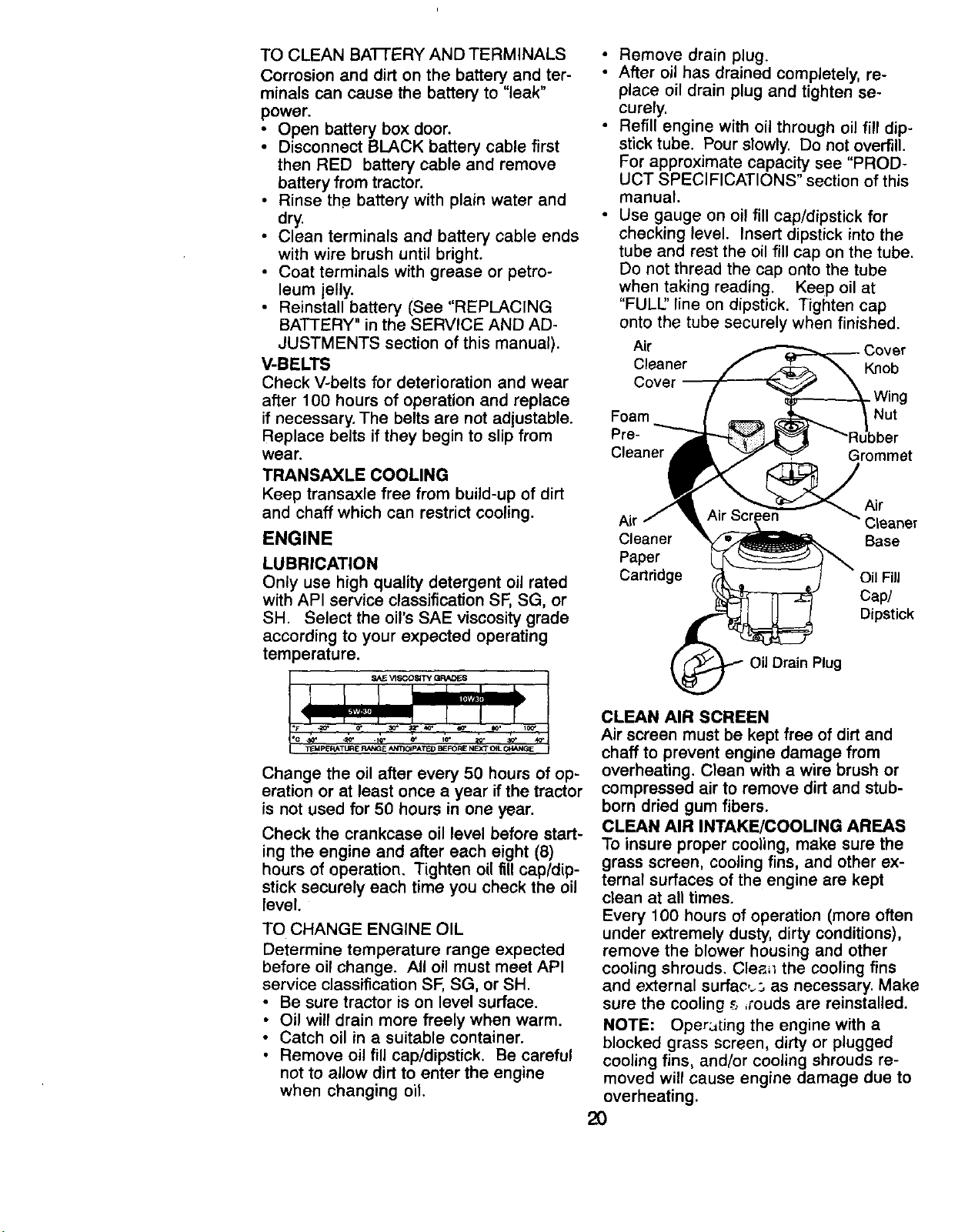
LUBRICATION
Only use high quality detergent oil rated
with API service classification SF, SG, or
SH. Select the oil's SAE viscosity grade
according to your expected operating
temperature.
Change the oil after every 50 hours of op-
eration or at least once a year if the tractor
is not used for 50 hours in one year.
Check the crankcase oil level before start-
ing the engine and after each eight (8)
hours of operation. Tighten oil fill cap/dip-
stick securely each time you check the oil
level.
TO CHANGE ENGINE OIL
Determine temperature range expected
before oil change. All oil must meet API
service classification SF, SG, or SH.
• Be sure tractor is on level surface.
• Oil will drain more freely when warm.
• Catch oil in a suitable container.
• Remove oil fill cap/dipstick. Be careful
not to allow dirt to enter the engine
when changing oil.
• Remove drain plug.
• After oil has drained completely, re-
place oil drain plug and tighten se-
curely.
• Refill engine with oil through oil fill dip-
stick tube. Pour slowly. Do not overfill.
For approximate capacity see "PROD-
UCT SPECIFICATIONS" section of this
manual.
• Use gauge on oi! fill cap/dipstick for
checking level. Insert dipstick into the
tube and rest the oil fill cap on the tube.
Do not thread the cap onto the tube
when taking reading. Keep oil at
"FULl" line on dipstick. Tighten cap
onto the tube securely when finished.
Air Cover
Cleaner Knob
Cover
Foam
Pre-
Cleaner
•Wing
Nut
Grommet
Air
Air 3leaner
Cleaner Base
Paper
Cartridge Oil Fill
Cap/
Dipstick
Oil Drain Plug
CLEAN AIR SCREEN
Air screen must be kept free of dirt and
chaff to prevent engine damage from
overheating. Clean with a wire brush or
compressed air to remove dirt and stub-
born dried gum fibers.
CLEAN AIR INTAKE/COOLING AREAS
To insure proper cooling, make sure the
grass screen, cooling fins, and other ex-
ternal surfaces of the engine are kept
clean at all times.
Every 100 hours of operation (more often
under extremely dusty, dirty conditions),
remove the blower housing and other
cooling shrouds. Clea=l the cooling fins
and external surfac,_ as necessary. Make
sure the cooling ._,,rouds are reinstalled.
NOTE: Oper:,[ing the engine with a
blocked grass screen, dirty or plugged
cooling fins, and/or cooling shrouds re-
moved will cause engine damage due to
overheating.
2O
AIR FILTER
Your engine will not run properly using a
dirty air filter. Clean the foam pre-cleaner
after every 25 hours of operation or every
season. Service paper cartridge every
100 hours of operation or every season,
whichever occurs first.
Service air cleaner more often under
dusty conditions.
• Remove knob and cover.
• Remove wing nut and air cleaner from
base.
TO SERVICE PRE-CLEANER
• Slide foam pre-cleaner off cartridge.
• Wash it in liquid detergent and water.
• Squeeze it dry in a clean cloth. Allow it
to dry.
• Saturate it in engine oil. Wrap it in
clean, absorbent cloth and squeeze to
remove excess oil.
TO SERVICE CARTRIDGE
• Replace a dirty, bent, or damaged car-
tridge.
NOTE: Do not wash the paper cartridge
or use pressurized air, as this will damage
the cartridge.
• Reinstall the pre-cleaner (cleaned and
oiled) over the paper cartridge.
• Reassemble air cleaner, wing nut,
cover and tighten knob securely.
MUFFLER
Inspect and replace corroded muffler and
spark arrester (if equipped) as it could
create a fire hazard and/or damage.
SPARK PLUGS
Replace spark plugs at the beginning of
each mowing season or after every 100
hours of operation, whichever occurs first.
Spark plug type and gap setting are
shown in "PRODUCT SPECIFICATIONS"
section of this manual.
ENGINE OIL FILTER
Replace the engine oil filter every season
or every other oil change if the tractor is
used more than 100 hours in one year.
• Drain oil from engine crankcase (See
"TO CHANGE ENGINE OIL_'in this sec-
tion of this manual, through step re-
move drain plug).
• Remove oil filter and wipe off filter
adapter.
• Apply a thin coating of new engine oil to
the rubber gasket on replacement oil fil-
ter.
• Install replacement oil filter on filter
adapter. Turn oil filter clockwise until
rubber gasket contacts the filter adapter,
then tighten filter an additional 1/2 turn.
• Fill crankcase with new oil (See "7-0
CHANGE ENGINE OI1" in this section of
this manual). For approximate capacity
see "PRODUCT SPECIFICATIONS"
section of this manual.
• Start the engine and check for oil leaks.
Correct any leaks before placing en-
gine into full operation.
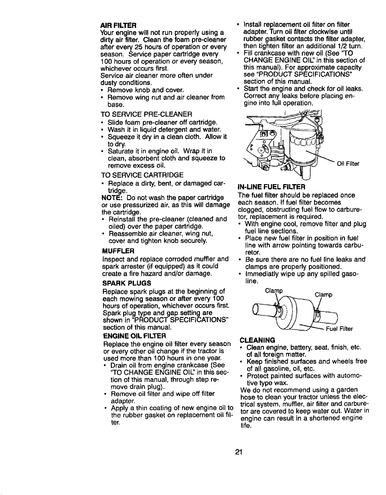
IN-LINE FUEL FILTER
Oil Filter
The fuel filter should be replaced once
each season. If fuel filter becomes
clogged, obstructing fuel flow to carbure-
tor, replacement is required.
• With engine cool, remove filter and plug
fuel line sections.
• Place new fuel filter in position in fuel
line with arrow pointing towards carbu-
retor.
• Be sure there are no fuel line leaks and
clamps are properly positioned.
• Immediatly wipe up any spilled gaso-
line.
Filter
CLEANING
• Clean engine, battery, seat, finish, etc.
of all foreign matter.
• Keep finished surfaces and wheels free
of all gasoline, oil, etc.
• Protect painted surfaces with automo-
tive type wax.
We do not recommend using a garden
hose to clean your tractor unless the elec-
trical system, muffler, air filter and carbure-
tor are covered to keep water out. Water in
engine can result in a shortened engine
life.
21
_CAUTION: Before.performing any service or adjustments:
Depress ciutch/braKe peaai Tullyana set parking crake.
Place gearshift lever in neutral (N) position.
Place attachment clutch in "DISENGAGED" position.
Turn ignition key "OFF" and remove key.
• Make sure the blades and all moving parts have completely stopped.
• Disconnect spark plug wire from spark plug and place wire where it cannot come
in contact with plug.
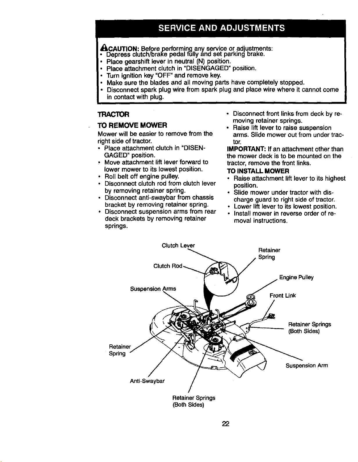
TRACTOR
TO REMOVE MOWER
Mower will be easier to remove from the
right side of tractor.
• Place attachment clutch in "DISEN-
GAGED" position.
• Move attachment lift lever forward to
lower mower to its lowest position.
• Roll belt off engine pulley.
• Disconnect clutch rod from clutch lever
by removing retainer spring.
• Disconnect anti-swaybar from chassis
bracket by removing retainer spring.
• Disconnect suspension arms from rear
deck brackets by removing retainer
springs.
• Disconnect front links from deck by re-
moving retainer springs.
• Raise lift lever to raise suspension
arms. Slide mower out from under trac-
tor.
IMPORTANT: If an attachment other than
the mower deck is to be mounted on the
tractor, remove the front links.
TO INSTALL MOWER
• Raise attachment lift lever to its highest
position.
• Slide mower under tractor with dis-
charge guard to right side of tractor.
• Lower lift lever to its lowest position.
• Install mower in reverse order of re-
moval instructions.
Clutch Lever
CIL
Suspension Arms
Retainer
Spring
Engine Pulley
Front Link
Retainer Springs
(Both Sides)
Retainer
Spdng
Suspension Arm
Anti-Swaybar
Retainer Springs
(Both Sides)
22
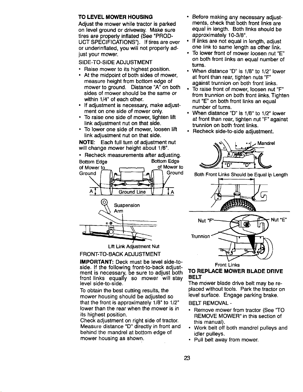
TO LEVEL MOWER HOUSING
Adjust the mower while tractor is parked
on level ground or driveway. Make sure
tires are properly inflated (See "PROD-
UCT SPECIFICATIONS"). If tires are over
or underinflated, you will not properly ad-
just your mower.
SIDE-TO-SIDE ADJUSTMENT
• Raise mower to its highest position.
• At the midpoint of both sides of mower,
measure height from bottom edge of
mower to ground. Distance "A" on both
sides of mower should be the same or
within 1/4" of each other.
• If adjustment is necessary, make adjust-
ment on one side of mower only.
• To raise one side of mower, tighten lift
link adjustment nut on that side.
• To lower one side of mower, loosen lift
link adjustment nut on that side.
NOTE: Each full turn of adjustment nut
will change mower height about 1/8".
• Recheck measurements after adjusting.
Bottom Edge Bottom Edge
of Mower to _ of Mower to
Grou__round
A--_-_-'_ Ground Li_le _'"'J -_'A
• Before making any necessary adjust-
ments, check that both front links are
equal in length. Both links should be
approximately 10-3/8".
• If links are not equal in length, adjust
one link to same length as other link.
• To lower front of mower loosen nut "E"
on both front links an equal number of
turns,
• When distance "D" is 1/8" to 1/2" lower
at front than rear, tighten nuts "F"
against trunnion on both front links.
• To raise front of mower, loosen nut "F"
from trunnion on both front links. Tighten
nut "E" on both front links an equal
number of turns.
• When distance "D" is 1/8" to 1/2" lower
at front than rear, tighten nut "F" against
trunnion on both front links.
• Recheck side-to-side adjustment.
_"_="'_, _ . -_=,_ Mandrel
Both Front Links Should be Equal ip Length
Suspension
Arm
Lift Link Adjustment Nut
FRONT-TO-BACK ADJUSTMENT
IMPORTANT: Deck must be level side-to-
side. If the following front-to-back adjust-
ment is necessary, be sure to adjust both
front links equally so mower will stay
level side-to-side.
To obtain the best cutting results, the
mower housing should be adjusted so
that the front is approximately 1/8" to 1/2"
lower than the rear when the mower is in
its highest position.
Check adjustment on right side of tractor.
Measure distance "D" directly in front and
behind the mandrel at bottom edge of
mower housing as shown.
Nut "F"_ _Nut
Trunnion "_, _
Front Links
TO REPLACE MOWER BLADE DRIVE
BELT
The mower blade drive belt may be re-
placed without tools. Park the tractor on
level surface. Engage parking brake.
BELT REMOVAL -
"E"
• Remove mower from tractor (See 'qO
REMOVE MOWER" in this section of
this manual).
• Work belt off both mandrel pulleys and
idler pulleys.
• Pull belt away from mower.
23
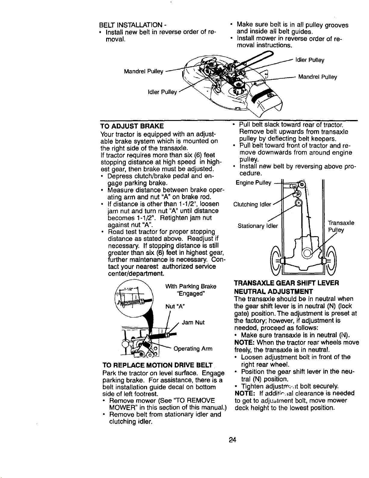
BELT INSTALLATION -
• Install new belt in reverse order of re-
moval.
Make sure belt is in all pulley grooves
and inside all belt guides.
• Install mower in reverse order of re-
moval instructions.
Mandrel Pulle_
Idler Pulley
ey
Mandrel Pulley
TO ADJUST BRAKE
Your tractor is equipped with an adjust-
able brake system which is mounted on
the right side of the transaxle.
If tractor requires more than six (6) feet
stopping distance at high speed in high-
est gear, then brake must be adjusted.
• Depress clutch/brake pedal and en-
gage parking brake.
• Measure distance between brake oper-
ating arm and nut "A" on brake rod.
• If distance is other than 1-1/2", loosen
jam nut and turn nut "A" until distance
becomes 1-1/2". Retighten jam nut
against nut "A".
• Road test tractor for proper stopping
distance as stated above. Readjust if
necessary. If stopping distance is still
greater than six (6) feet in highest gear,
further maintenance is necessary. Con-
tact your nearest authorized service
center/department.
With Parking Brake
"Engaged"
Nut "A"
/,,Jam Nut
oO_Operating Arm
TO REPLACE MOTION DRIVE BELT
Park the tractor on level surface. Engage
parking brake. For assistance, there is a
belt installation guide decal on bottom
side of left footrest.
• Remove mower (See 'q-O REMOVE
MOWER" in this section of this manual.)
• Remove belt from stationary idler and
clutching idler.
• Pull belt slack toward rear of tractor.
Remove belt upwards from transaxle
pulley by deflecting belt keepers.
• Pull belt toward front of tractor and re-
move downwards from around engine
pulley.
• Install new belt by reversing above pro-
cedure.
Engine Pulley --
Clutching Idler j
J
Stationary Idler
Transaxle
0
TRANSAXLE GEAR SHIFT LEVER
NEUTRAL ADJUSTMENT
The transaxle should be in neutral when
the gear shift lever is in neutral (N) (lock
gate) position. The adjustment is preset at
the factory; however, if adjustment is
needed, proceed as follows:
• Make sure transaxle is in neutral (N).
NOTE: When the tractor rear wheels move
freely, the transaxle is in neutral.
• Loosen adjustment bolt in front of the
right rear wheel.
• Position the gear shift lever in the neu-
tral (N) position.
• Tighten adjustm,.,_t bolt securely.
NOTE: If additir.:_al clearance is needed
to get to adjustment bolt, move mower
deck height to the lowest position.
24
Lever
/ Neutral Lock
/ "_" Gate
Adj Bolt
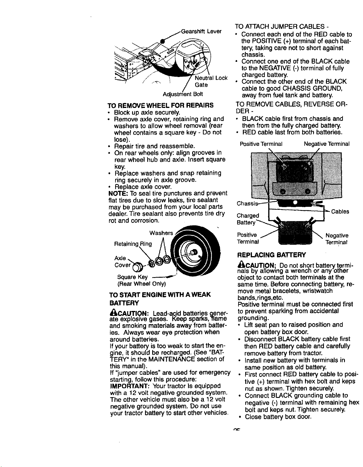
TO REMOVE WHEEL FOR REPAIRS
• Block up axle securely.
• Remove axle cover, retaining ring and
washers to allow wheel removal (rear
wheel contains a square key - Do not
lose).
• Repair tire and reassemble.
• On rear wheels only: align grooves in
rear wheel hub and axle. Insert square
key.
• Replace washers and snap retaining
ring securely in axle groove.
• Replace axle cover.
NOTE: To seal tire punctures and prevent
flat tires due to slow leaks, tire sealant
may be purchased from your local parts
dealer. Tire sealant also prevents tire dry
rot and corrosion.
Washers.,'__
Axle ..
Cover_!
Square Key
(Rear Wheel Only)
TO START ENGINE WITH A WEAK
BATrERY
_kCAUTION: Lead-acid batteries aener-
ate explosive gases. Keep sparks,'flame
and smoking materials away from batter-
ies. Always wear eye protection when
around batteries.
If your battery is too weak to start the en-
gine, it should be recharged. (See "BAT-
TERY" in the MAINTENANCE section of
this manual).
If "jumper cables" are used for emergency
starting, follow this procedure:
IMPORTANT: Your tractor Is equipped
with a 12 volt negative grounded system.
The other vehicle must also be a 12 volt
negative grounded system. Do not use
your tractor battery to start other vehicles.
TO ATTACH JUMPER CABLES -
• Connect each end of the RED cable to
the POSITIVE (+) terminal of each bat-
tery, taking care not to short against
chassis.
• Connect one end of the BLACK cable
to the NEGATIVE (-) terminal of fully
charged battery.
• Connect the other end of the BLACK
cable to good CHASSIS GROUND,
away from fuel tank and battery.
TO REMOVE CABLES, REVERSE OR-
DER -
• BLACK cable first from chassis and
then from the fully charged battery.
• RED cable last from both batteries.
Positive Terminal
Negative Terminal
Charged
Batten
Positive Negative
Terminal Terminal
REPLACING BATTERY
n_alC,AUT!,ON:. Do not short battery t.ermi-
s Dy allowing a wrench or any oTner
object to contact both terminals at the
same time. Before connecting battery, re-
move metal bracelets, wristwatch
bands,rings,etc.
Positive terminal must be connected first
to prevent sparking from accidental
grounding.
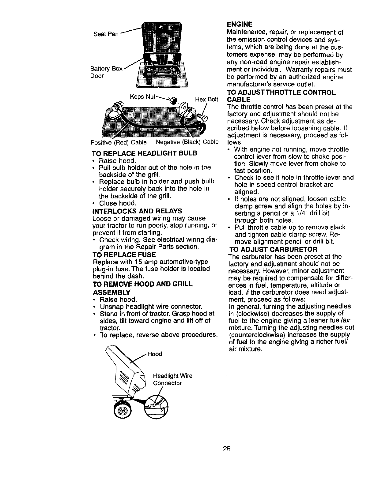
• Lift seat pan to raised position and
open battery box door.
• Disconnect BLACK battery cable first
then RED battery cable and carefully
remove battery from tractor.
• Install new battery with terminals in
same position as old battery.
• First connect RED battery cable to posi-
tive (+) terminal with hex bolt and keps
nut as shown. Tighten securely.
• Connect BLACK grounding cable to
negative (-) terminal with remaining hex
bolt and keps nut. Tighten securely.
• Close battery box door.
Seat Pan
Battery
Door
Hex Bolt
Positive (Red) Cable Negative (Black) Cable
TO REPLACE HEADLIGHT BULB
• Raise hood.
• Pull bulb holder out of the hole in the
backside of the grill.
• Replace bulb in holder and push bulb
holder securely back into the hole in
the backside of the grill.
• Close hood.
INTERLOCKS AND RELAYS
Loose or damaged wiring may cause
your tractor to run poorly, stop running, or
prevent it from starting.
• Check wiring. See electrical wiring dia-
gram in the Repair Parts section.
TO REPLACE FUSE
Replace with 15 amp automotive-type
plug-in fuse. The fuse holder is located
behind the dash.
TO REMOVE HOOD AND GRILL
ASSEMBLY
• Raise hood.
• Unsnap headlight wire connector.
• Stand in front of tractor. Grasp hood at
sides, tilt toward engine and lift off of
tractor.
• To replace, reverse above procedures.
H°_iadlightWire
ctor
ENGINE
Maintenance, repair, or replacement of
the emission control devices and sys-
tems, which are being done at the cus-
tomers expense, may be performed by
any non-road engine repair establish-
ment or individual. Warranty repairs must
be performed by an authorized engine
manufacturer's service outlet.
TO ADJUST THROTTLE CONTROL
CABLE
The throttle control has been preset at the
factory and adjustment should not be
necessary. Check adjustment as de+
scribed below before loosening cable. If
adjustment is necessary, proceed as fol-
lows:
• With engine not running, move throttle
control lever from slow to choke posi-
tion. Slowly move lever from choke to
fast position.
• Check to see if hole in throttle lever and
hole in speed control bracket are
aligned,
° If holes are not aligned, loosen cable
clamp screw and align the holes by in-
serting a pencil or a 1/4" drill bit
through both holes.
• Pull throttle cable up to remove slack
and tighten cable clamp screw. Re-
move alignment pencil or drill bit.
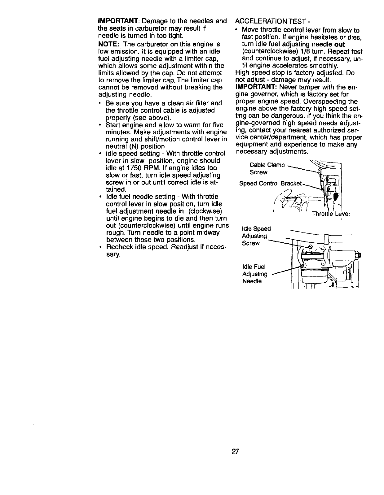
TO ADJUST CARBURETOR
The carburetor has been preset at the
factory and adjustment should not be
necessary. However, minor adjustment
may be required to compensate for differ-
ences in fuel, temperature, altitude or
load. If the carburetor does need adjust-
ment, proceed as follows:
In general, turning the adjusting needles
in (clockwise) decreases the supply of
fuel to the engine giving a leaner fuel/air
mixture. Turning the adjusting needles out
(counterclockwise) increases the supply
of fuel to the engine giving a richer fuel/
air mixture.
_R
IMPORTANT: Damage to the needles and
the seats in carburetor may result if
needle is turned in too tight.
NOTE: The carburetor on this engine is
low emission. It is equipped with an idle
fuel adjusting needle with a limiter cap,
which allows some adjustment within the
limits allowed by the cap. Do not attempt
to remove the limiter cap. The limiter cap
cannot be removed without breaking the
adjusting needle.
• Be sure you have a clean air filter and
the throttle control cable is adjusted
properly (see above).
• Start engine and allow to warm for five
minutes. Make adjustments with engine
running and shift/motion control lever in
neutral (N) position.
• Idle speed setting - With throttle control
lever in slow position, engine should
idle at 1750 RPM. If engine idles too
slow or fast, turn idle speed adjusting
screw in or out until correct idle is at-
tained.
• Idle fuel needle setting - With throttle
control lever in slow position, turn idle
fuel adjustment needle in (clockwise)
until engine begins to die and then turn
out (counterclockwise) until engine runs
rough. Turn needle to a point midway
between those two positions.
• Recheck idle speed. Readjust if neces-
sary.
ACCELERATION TEST -
• Move throttle control lever from slow to
fast position. If engine hesitates or dies,
turn idle fuel adjusting needle out
(counterclockwise) 1/8 turn. Repeat test
and continue to adjust, if necessary, un-
til engine accelerates smoothly.
High speed stop is factory adjusted. Do
not adjust - damage may result.
IMPORTANT: Never tamper with the en-
gine governor, which is factory set for
proper engine speed. Overspeeding the
engine above the factory high speed set-
ting can be dangerous. If you think the en-
.gine-governed high speed needs adjust-
rag, contact your nearest authorized ser-
vice center/department, which has proper
equipment and experience to make any
necessary adjustments.
Cable Clamp _
Screw _l
Speed Control Br__ /
_Throttle Lever
Idle Speed
Adjusting ___
Screw _
Idle Fuel
Adjusting
Needle
27
Immediately prepare your tractor for stor-
age at the end of the season or if the trac-
tor will not be used for 30 days or more.
_L,CAUTION: Never store the tractor with
gasoline in the tank inside a building
where fumes may reach an open flame or
spark. Allow the engine to cool before
storing in any enclosure.
TRACTOR
Remove mower from tractor for winter
storage. This will allow you to clean it thor-
oughly. Remove all dirt, grease, leaves,
etc. Store in a clean, dry area.
• Clean entire tractor (See "CLEANING"
in the Maintenance section of this
manual).
• Inspect and replace belts, if necessary
(See belt replacement instructions in
the Service and Adjustments section of
this manual).
• Lubricate as shown in the Maintenance
section of this manual.
• Be sure that all nuts, bolts and screws
are securely fastened. Inspect moving
parts for damage, breakage and wear.
Replace if necessary.
• Touch up all rusted or chipped paint
surfaces; sand lightly before painting.
BATTERY
• Fully charge the battery for storage.
• After a period of time in storage, battery
may require recharging.
• To help prevent corrosion and power
leakage during long periods of storage,
battery cables should be disconnected
and battery cleaned thoroughly (see
'30 CLEAN BAI-rERY AND TERMI-
NALS" in the Maintenance section of
this manual).
• After cleaning, leave cables discon-
nected and place cables where they
cannot come in contact with battery ter-
minals.
• If battery is removed from tractor for
storage, do not store battery directly on
concrete or damp surfaces.
ENGINE
FUEL SYSTEM
IMPORTANT: It is important to prevent
gum deposits from forming in essential
fuel system parts such as carburetor, fuel
filter, fuel hose, or tank during storage.
Also, experience indicates that alcohol
blended fuels (called gasohol or using
ethanol or methanol) can attract moisture
which leads to separation and formation
of acids during storage. Acidic gas can
damage the fuel system of an engine
while in storage.
• Drain the fuel tank.
• Start the engine and let it run until the
fuel lines and carburetor are empty.
• Never use engine or carburetor cleaner
products in the fuel tank or permanent
damage may occur.
• Use fresh fuel next season.
NOTE: Fuel stabilizer is an acceptable al-
ternative in minimizing the formation of
fuel gum deposits during storage. Add
stabilizer to gasoline in fuel tank or stor-
age container. Always follow the mix ratio
found on stabilizer container. Run engine
at least 10 minutes after adding stabilizer
to allow the stabilizer to reach the carbu-
retor. Do not drain the gas tank and carbu-
retor if using fuel stabilizer.
ENGINE OIL
Drain oil (with engine warm) and replace
with clean engine oil. (See "ENGINE" in
the Maintenance section of this manual).
CYLINDER(S)
• Remove spark plug(s).
• Pour one ounce of oil through spark
plug hole(s) into cylinder(s).
• Turn ignition key to "START" position for
a few seconds to distribute oil.
• Replace with new spark plug(s).
OTHER
• Do not store gasoline from one season
to another.
• Replace your gasoline can if it starts to
rust. Rust and/or dirt in your gasoline
will cause problems.
• If possible, store your tractor indoors
and cover it to give protection from dust
and dirt.
• Cover your tractor with a suitable pro-
tective cover thr_ Joes not retain mois-
ture. Do not _ ;_ plastic. Plastic cannot
breathe, which allows condensation to
form and cause your tractor to rust.
IMPORTANT: Never cover tractor while
engine and exhaust areas are still warm.
28
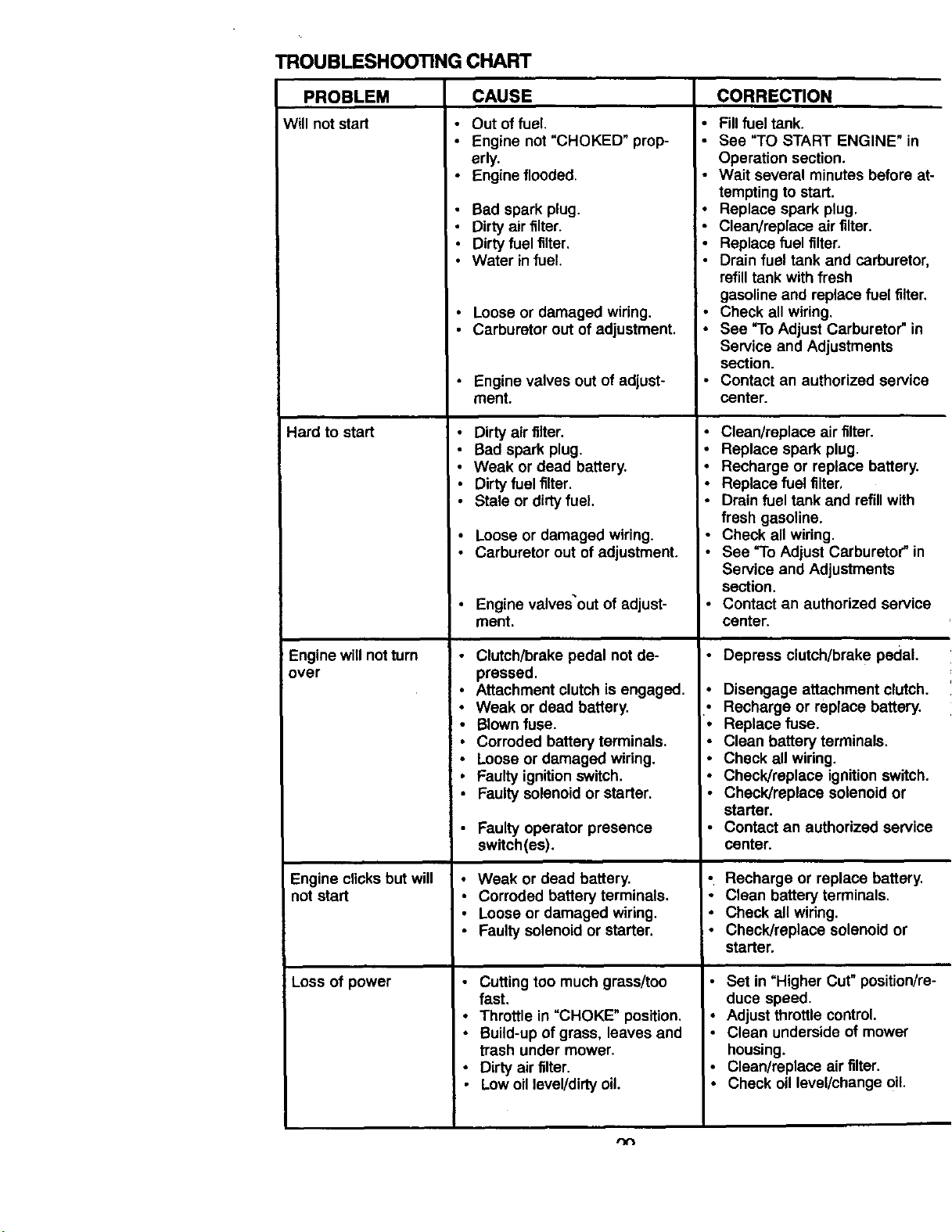
TROUBLESHOOTING CHART
PROBLEM CAUSE
Will not start • Out of fuel
Hard to start
Engine will notturn
over
Engine clicks but will
not start
Loss of power
• Engine not "CHOKED" prop-
erly.
Engine flooded.
Bad spark plug.
Dirty air filter.
Dirty fuel filter.
Water infuel.
• Loose or damaged wiring.
• Carburetor out of adjustment.
• Engine valves out of adjust-
ment.
• Dirty air filter.
• Bad spark plug.
• Weak or dead battery.
• Dirty fuel filter.
• Stale or dirtyfuel.
• Loose or damaged wiring.
• Carburetor out of adjustment.
• Engine valves out of adjust-
ment.
! • Clutch/brake pedal not de-
pressed.
• Attachment clutch is engaged.
• Weak or dead battery.
• Blown fuse.
• Corroded battery terminals.
• Loose or damaged wiring.
• Faulty ignitionswitch.
• Faulty solenoid or starter.
• Faulty operator presence
switch(ss).
• Weak or dead battery.
• Corroded battery terminals.
• Loose or damaged wiring,
• Faulty solenoid or starter.
• Cutting too much grass/too
fast.
• Throttle in "CHOKE" position.
• Build-up of grass, leaves and
trash under mower.
• Dirty air filter.
• Low oil level/dirty oil.
CORRECTION
• Fill fuel tank.
• See "TO START ENGINE" in
Operation section.
• Wait several minutes before at-
tempting to start.
• Replace spark plug.
• Clean/replace air filter.
• Replace fuel filter.
Drain fuel tank and carburetor,
refilltank with fresh
gasoline and replace fuel filter.
Check all wiring.
See "To Adjust Carburetor" in
Service and Adjustments
section.
• Contact an authorized service
center.
• Clean/replace air filter.
• Replace spark plug.
• Recharge or replace battery.
• Replace fuel filter,
• Drain fuel tank and refill with
fresh gasoline.
• Check all wiring.
• See "To Adjust Carburetor" in
Service and Adjustments
section.
• Contact an authorized service
center.
• Depress clutch/brake pedal.
• Disengage attachment clutch.
• Recharge or replace battery.
• Replace fuse.
• Clean battery terminals.
• Check all wiring.
• Check/replace ignitionswitch.
Check/replace solenoid or
starter.
Contact an authorized service
center.
• Recharge or replace battery.
• Clean battery terminals.
• Check all widng.
• Check/replace solenoid or
starter.
• Set in =Higher Cut" position/re-
duce speed.
• Adjust throttle control.
• Clean underside of mower
housing.
• Clean/replace air filter.
• Check oil level/change oil.
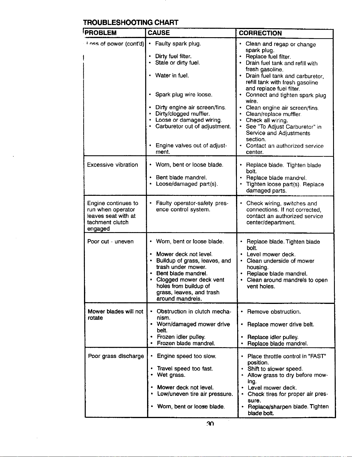
TROUBLESHOOTING CHART
PROBLEM
_ of Dower (cont'd)
Excessive vibration
Engine continues to
run when operator
leaves seat with at
tachment clutch
engaged
Poor cut - uneven
Mower blades will not
rotate
Poor grass discharge
CAUSE
• Faulty spark plug.
Dirty fuel filter.
• Stale or dirtyfuel.
Water in fuel.
Spark plug wire loose.
Dirty engine air screen/fins.
Dirty/clogged muffler.
Loose or damaged wiring.
Carburetor out of adjustment.
Engine valves out of adjust-
ment.
• Worn, bent or loose blade,
• Bent blade mandrel.
• Loose/damaged part(s).
• Faulty operator-safety pres-
ence control system.
• Worn, bent or loose blade.
• Mower deck not level.
• Buildupof grass, leaves, and
trash under mower.
• Bent blade mandrel.
• Clogged mower deck vent
holes from buildup of
grass, leaves, and trash
around mandrels.
• Obstruction in clutch mecha-
nism.
i " Worn/damaged mower drive
belt.
• Frozen idler pulley.
• Frozen blade mandrel.
• Engine speed too slow.
• Travel speed too fast.
• Wet grass.
Mower deck not level.
Low/uneven tire air pressure.
• Worn, bent or loose blade.
CORRECTION
Clean and regap or change
spark plug.
Replace fuel filter.
Drain fuel tank and refillwith
fresh gasoline.
Drain fuel tank and carburetor,
refilltank with fresh gasoline
and replace fuel filter.
Connect and tighten spark plug
wire.
Clean engine air screen/fins,
Clean/replace muffler.
Check all wiring.
See "To Adjust Carburetor" in
Service and Adjustments
section.
Contact an authorized service
center.
• Replace blade. Tighten blade
bolt.
• Replace blade mandrel.
• Tighten loose part(s). Replace
damaged parts.
• Check wiring, switches and
connections. If not corrected,
contact an authorized service
center/department,
• Replace blade. Tighten blade
bolt.
• Level mower deck.
• Clean underside of mower
housing.
• Replace blade mandrel.
• Clean around mandrels to open
vent holes.
• Remove obstruction.
• Replace mower drive belt.
I - Replace idler pulley.
• Replace blade mandrel.
Place throttle control in "FAST"
position.
• Shift to slower speed.
• Allow grass to dry before mow-
ing.
• Level mower deck.
• Check tires for proper air pres-
sure.
• Replace/sharpen blade. Tighten
blade bolt.
t4n
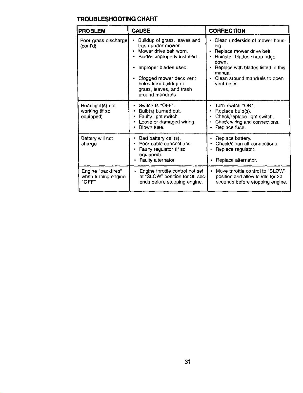
TROUBLESHOOTING CHART
PROBLEM
Poor grass discharg_
(cont'd)
Headlight(s) not
working (if so
equipped)
,,,. ,.
Battery will not
charge
CAUSE CORRECTION
• Buildup of grass, leaves and
trash under mower.
• Mower drive belt worn.
• Blades improperly installed.
• Improper blades used.
• Clogged mower deck vent
holes from buildup of
grass, leaves, and trash
around mandrels.
• Switch is "OFF".
• Bulb(s) burned out.
Faulty light switch.
• Loose or damaged wiring.
Blown fuse.
Bad battery cell(s).
Poor cable connections.
Faulty regulator (if so
equipped).
Faulty alternator.
• Clean underside of mower hous-
ing.
• Replace mower drive belt.
• Reinstall blades sharp edge
down.
• Replace with blades listed in this
manual.
• Clean around mandrels to open
vent holes.
• Turn switch "ON".
• Replace bulb(s).
• Check/replace light switch.
• Check wiring and connections.
• Replace fuse.
Replace battery.
Check/clean all connections.
Replace regulator.
• Replace alternator.
Engine "backfires" • Engine throttle control not set Move throttle control to "SLOW"
when turning engine at "SLOW" position for 30 sec- position and allow to idle fpr 30
"OFF" onds before stopping engine, seconds before stopping engine.
31

32
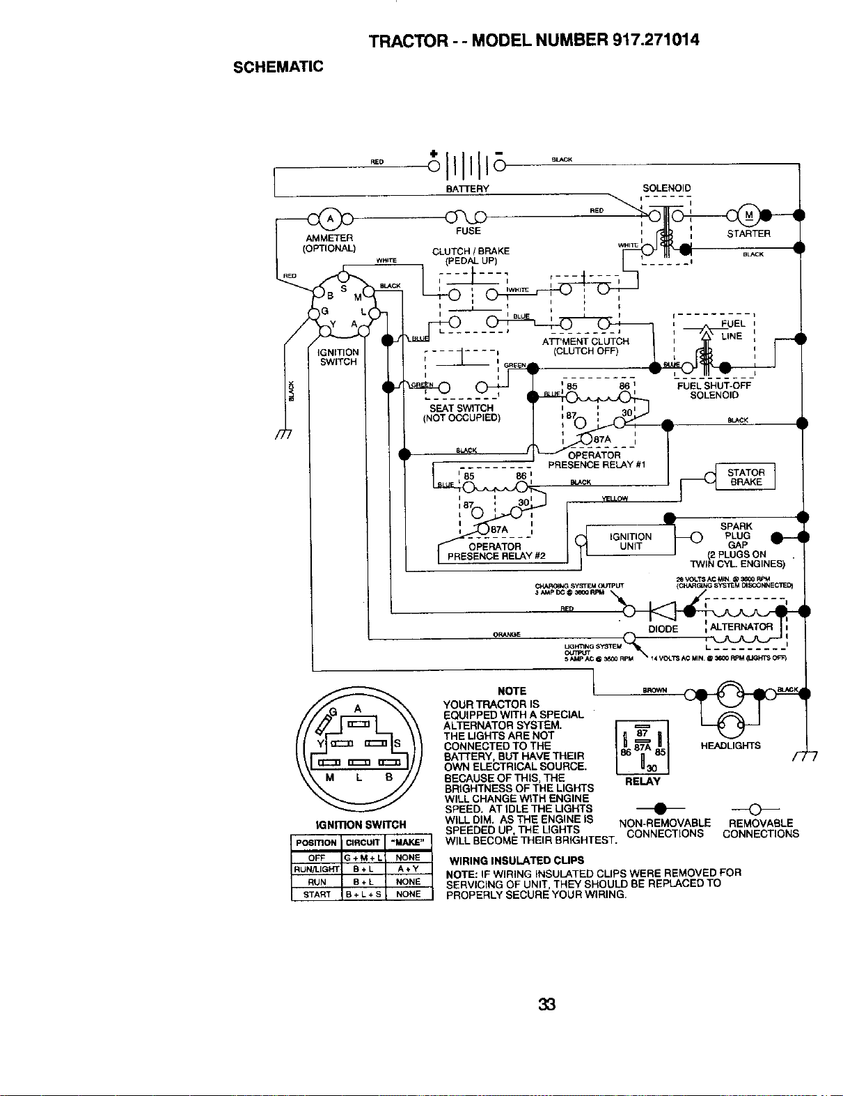
SCHEMATIC
TRACTOR - - MODEL NUMBER 917.271014
RED
BATTERY SOLENOID
I- i
FUSE ',_ STARTER
CLUTCH/ BRAKE wHl_ _ a_CK
(PEDALUP)
•
I II IWHI_
FUEL
L ....... I
ATT'MENTCLUTCH
.... _ (CLUTCHOFF)
, 1--- ,,
1 -- (
I
86 I FUELSHUT-OFF
SOLENOID
SEATSWITCH
(NOTOCCUPIED) SL_CK
8L_K
185 86 I
L i
i I i
87 ', 30
87A I
OPEF_TOR-
#2
OR_QE
STATOR 1
BRAKE
_LLOW
_) SPARK
IGNITION PLUG _-
UNIT GAP
(2 PLUGS ON
TWIN CYL. ENGINES)
_ _LTS AC _IN O 36_0 RPM
CHi_=IG}NG SYSTEM O_J'PPUT (C_&RG_NG SYSTEM DtSCONNECTED)
DIODE =
UGHT1NG S_'JTEM L ......... I
|G NITION SWITCH
POSITION I CIRCUIT "MAKE"
OFF I G + M + L NONE
RUN/LIGHT B + L A + Y
RUN B + L NONE
START B + L + S NONE
NOTE
YOUR TRACTOR IS
EQUIPPED WITH A SPECIAL
ALTERNATOR SYSTEM.
THE UGHTS ARE NOT
CONNECTED TO THE
BATTERY, BUT HAVE THEIR
OWN ELECTRICAL SOURCE.
BECAUSE OF THIS, THE
BRIGHTNESS OFTHE LIGHTS
WILL CHANGE WITH ENGINE
SPEED. AT IDLE THE LIGHTS
WtLL DIM. AS THE ENGINE IS
SPEEDED UP, THE UGHTS
RELAY
HEADLIGHTS
/-
WILL BECOME THEIR BRIGHTEST.
NON-REMOVABLE
CONNECTIONS
REMOVABLE
CONNECTIONS
WIRING INSULATED CUPS
NOTE: IF WIRING INSULATED CLIPS WERE REMOVED FOR
SERVICING OF UNIT, THEY SHOULD BE REPLACED TO
PROPERLY SECURE YOUR WIRING.
33
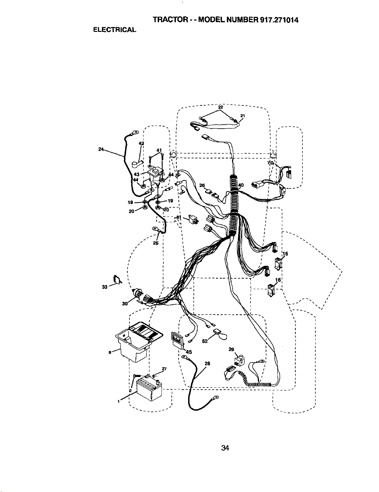
ELECTRICAL
TRACTOR - - MODEL NUMBER 917.271014
I
I
24 41
I
I
,!
#
##
34
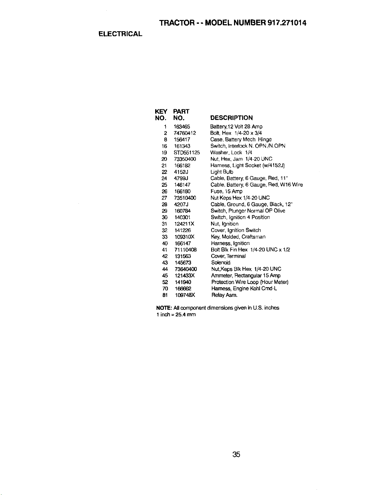
ELECTRICAL
TRACTOR - - MODEL NUMBER 917.271014
KEY PART
NO, NO.
t 163465
2 74760412
8 156417
16 161343
19 STD551125
2O 733504O0
21 166182
22 4152J
24 4799J
25 146147
26 166180
27 73510400
28 4207J
29 160784
30 140301
31 124211X
32 141226
33 109310X
40 166147
41 71110408
42 131563
43 145673
44 7364040O
45 121433X
52 141940
70 166662
81 109748)(
DESCRIPTION
Battery,12 Vo!t28 Amp
Bolt, Hex 1/4-20 x 3/4
Case, Battery Mesh Hinge
Switch, Interlock N.OPN./N.CPN
Washer, Lock 1/4
Nut, Hex, Jam 1/4-20UNC
Harness, Light Socket (w/4152J)
Light Bulb
Cable, Battery, 6 Gauge, Red, 11"
Cable, Battery, 6 Gauge, Red,W16 Wire
Fuse, 15Amp
NutKeps Hex 1/4-20UNC
Cable, Ground, 6 Gauge, BLack,!2"
Switch, Plunger Normal OP Clive
Switch, Ignition 4 Position
Nut, Ignition
Cover, Ignition Switch
Key,Molded, Craftsman
Harness, Ignition
Bolt BIk Fin Hex 1/4-20 UNC x 1/2
Cover,Terminal
Solenoid
Nut,Keps BIkHex 1/4-20 UNC
Ammeter, Rectangular 15 Amp
Protection Wire Loop (Hour Meter)
Hamese, Engine Kohl Cmd-L
Relay Asm.
NOTE: All component dimensions given in U.S. inches
1 inch=25.4 mm
35
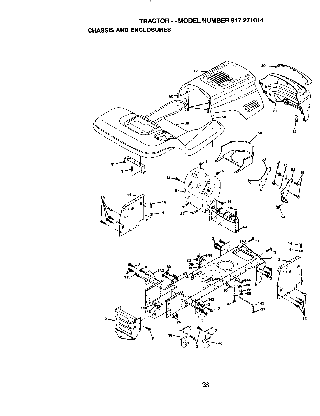
TRACTOR - - MODEL NUMBER 917.271014
CHASSIS AND ENCLOSURES
28
58 12
36
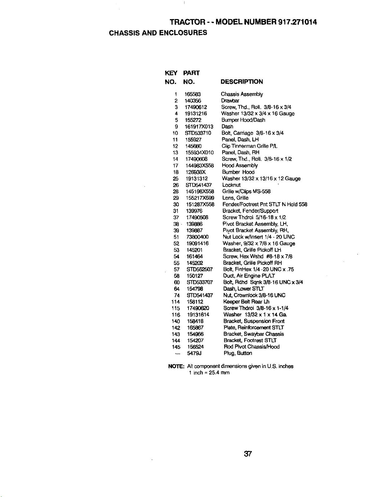
TRACTOR - - MODEL NUMBER 917.271014
CHASSIS AND ENCLOSURES
KEY PART
NO. NO. DESCRIPTION
1 165583
2 140356
3 17490612
4 19131216
5 155272
9 161917)(013
10 STD533710
11 155927
12 145660
13 155934X010
14 17490608
17 144983X558
18 126_38X
25 19131312
26 s'rD541437
28 14519_X558
29 155217X599
30 151287X558
31 139976
37 17490508
38. 139886
39 139887
51 738004O0
52 19091416
53 145201
54 161464
55 1452O2
57 STD552507
5B 150127
6O Sl13533707
64 154798
74 STD541437
114 158112
115 17490620
116 19131614
140 158418
142 165867
143 154966
144 154207
145 156524
-- 5479J
NOTE:
Chassis Assembly
Dra..Voar
Screw,Thd., Roll. 3/8-16 x 3/4
Washer 13/32 x 3/4 x 16 Gauge
Bumper Hood/Dash
Dash
Bolt, Carriage 3/8-16 x 3/4
Panel, Dash, LH
ClipTinnerman Grille P/L.
Panel,Dash, RH
Screw,Thd., Roll. 3/8-16 x 1/2
Hood Assembly
Bumper Hood
Washer 13/32 x 13/16 x 12Gauge
Locknut
GdlLew/ClipsMS-558
Lens, Grille
FendedFootrest Pnt STLT N Held 558
Bracket, Fender/Support
Screw Thdrol 5/t6-18 x 1/2
Pivot Bracket Assembly, LH,
Pivot BracketAssembly, RH,
Nut Lock w/Insert 1/4 - 20 UNC
Washer, 9/32 x 7/8 x 16 Gauge
Bracket, Grille Pickoff LH
Screw, HexWshd #8-18 x 7/8
Bracket, Grille Pickoff RH
Bolt, FinHex 1/4 -29 UNC x .75
Duet, Air Engine PLAT
Bolt, Rdhd Sqnk 3/8-16 UNC x 3/4
Dash, Lower STLT
Nut,Crownlock 3/8-16 UNC
KeeperBeltRear Lh
ScrewThdrot 3/8-16x 1-1/4
Washer 13/32x 1 x14Ga.
Bracket,SuspensionFront
Plate, ReinforcementSTLT
Bracket,Swaybar Cha_is
Bracket,FootrestSTLT
Rod PivotChassis/Hood
Plug, Button
All component dimensions given in U.S. inshse
1 inch = 25.4 mm
37
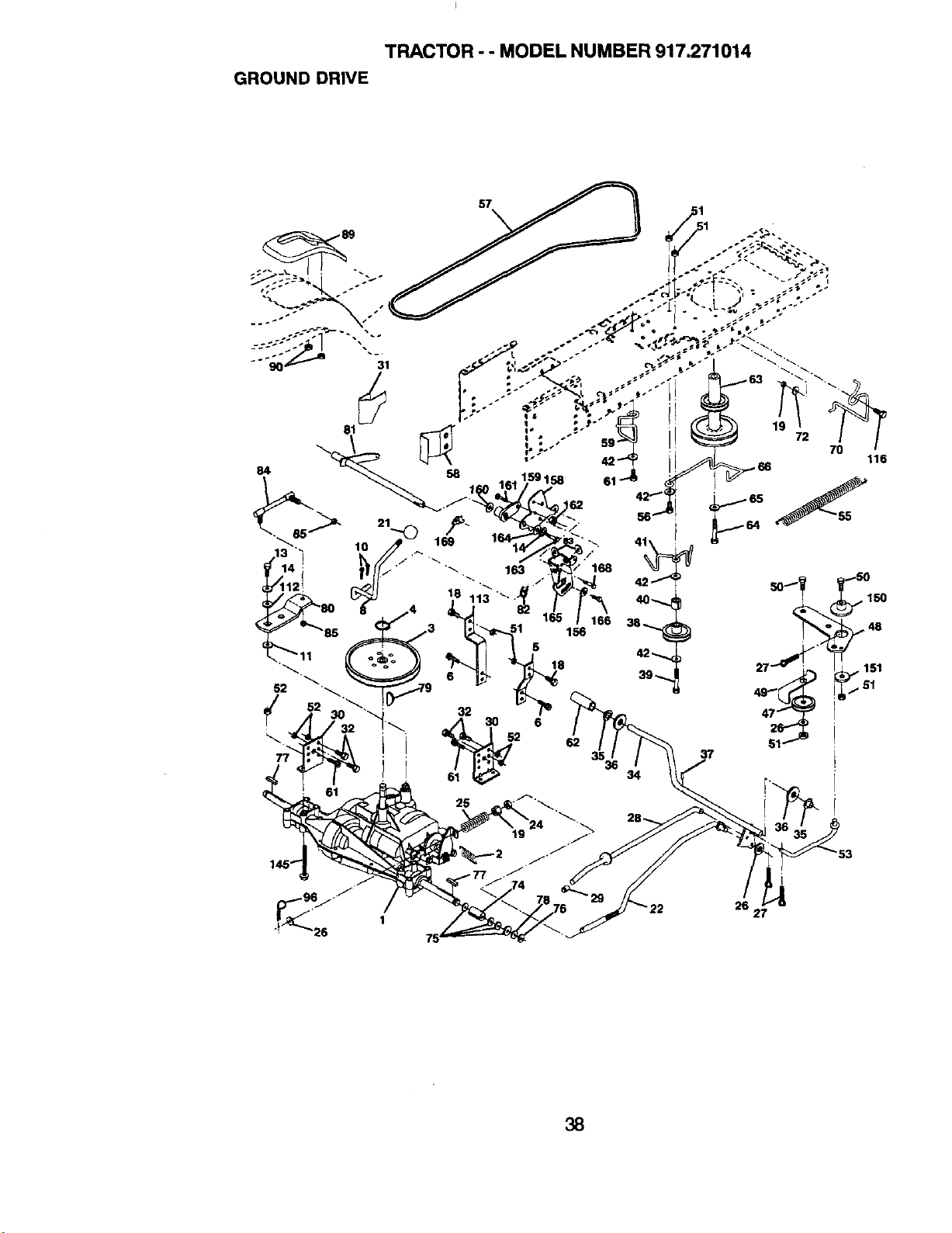
TRACTOR - - MODEL NUMBER 917.271014
GROUND DRIVE
57
,62
80 ,o 113 ". P"
85 3 " 51 156
/ - "1"_ A 30 6 / g
37
116
25
I
26 27
38
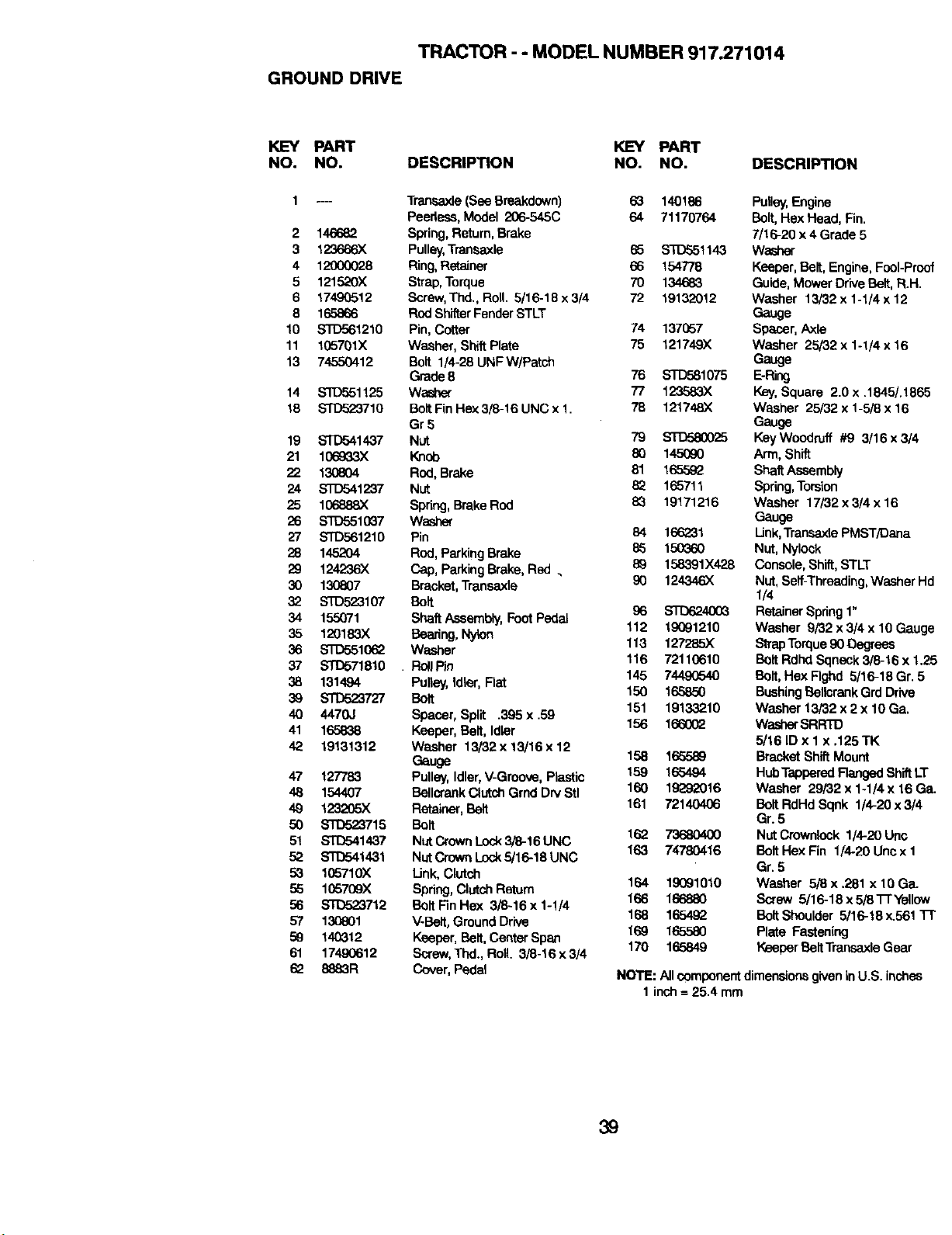
TRACTOR - - MODEL NUMBER 917.271014
GROUND DRIVE
KEY PART KEY PART
NO. NO. DESCRIPTION NO. NO. DESCRIPTION
2
3
4
5
6
8
10
11
13
14
18
19
21
22
24
25
26
27
28
29
3O
32
34
35
36
37
38
39
40
41
42
47
48
49
50
51
52
53
55
56
57
59
61
62
.... Trenasxle(See Breakdown) 63 140186
Peedass,Model 206-545C 64 71170764
146682 Spring,Return,Brake
123O66X Pulley,Tranasxle 65 STD551143
12000028 Ring, Retainer 66 154778
121520X Strap,Torque 70 134683
17490512 Screw,Thd., Roll. 5/16-18 x3/4 72 19132012
165866 RodShitter FenderSTLT
STD561210 Pin, Cotter 74 137057
165701X Washer, ShiftPlate 75 121749X
74550412 Bolt 1/4-28 UNFW/Patch
Grade8 76 STD581075
STI7o51125 Washer 77 123583X
STD523710 BoltFin Hex3/8-16 UNC x1. 78 121748X
Gr 5
STD541437 Nut 79 STD53O025
106933X Knob 80 145090
130804 Rod, Brake 81 165592
STD541237 Nut 82 165711
106888)( Spring,Brake Rod 83 19171216
S'1"_,5510_7 Washer
S'[D561210 Pin 84 166231
145204 Rod, PerkingBrake 85 150_60
1242"36)( Cap, ParkingBrake, Red • 89 158391X428
130807 Bracket,Transaxle 90 124346)(
STO523107 Bolt
155071 ShaftAssembly,FootPedal 96 ST[36243O_
112 19691210
120183X Bearing,Nylen
STD551062 Washer 113 127285X
STD571810 . R_lPin 116 72110610
131494 Pulley, Idler, Flat 145 7449G540
S'FD523727 Bolt 150 165850
4470.1 Spacer, Split .395 x .59 151 19133210
165838 Keeper, Belt, Idler 156 166002
19131312 Washer 13/32 x 13/16 x12
Gauge 158 165589
127783 Pulley,Idler,V-Groove, Plastic 159 165494
154407 BellcrankClutchGrnd DryStl 160 19_920!6
123_05X Retainer, Belt 161 72140406
_715 Bolt
$1"[To41437 NutCrownLock3/8-16 UNC 162 73680400
STD541431 NutCrownLock5/16-18 UNC 163 74780416
105710X Link,Clutch
105709X Spring,ClutchReturn 164 19091010
STD523712 BoltFinHex 3/6-16x1-1/4 166 166880
130801 V-Belt,GroundDrive 168 1654.92
140312 Keeper, Belt,Center Span 169 165580
17490612 Serew,Thd., Roll. 3/8-16x3/4 170 165849
8883R Cover, Pedal
Pulley,Engine
Bolt, Hex Head, Fin.
7/16-20 x4 Grade 5
Washer
Keeper,Bolt, Engine,FooI-Preef
Guide,Mower Drive Bolt, R.H.
Washer 13/32 x 1-1/4 x 12
Gauge
Spacer, Axle
Washer 25/32 x 1-1/4 x 16
Gauge
E-Ring
Key,Square 2.0 x .1845/.1865
Washer 25/32 x 1-5/8 x 16
Gauge
Key Woodruff #9 3/16 x 3/4
Arm, Shift
ShaftAssembly
Spring,Torsion
Washer 17/32 x 3/4 x 16
Gauge
Link,Transaxle PMSTK)ana
Nut, Nylock
Console, Shift,STLT
Nut, Serf-Threading,Washer Hd
I/4
Retainer Spring 1"
Washer 9/32 x 3/4 x 10 Gauge
StrapTorque90 Oegrass
Belt Rdhd Sqneck 3/8-16 x 1.25
Belt, Hex Flghd 5/16-18 Gr. 5
Bushing BellcrankGrdDrive
Washer 13/32 x 2 x 10 GeL
WasherSRRTD
5/16 ID x 1 x .125 TK
Bracket ShiftMount
HubTapperedRanged ShiftLT
Washer 29/32 x 1-1/4 x 16 GeL
Bolt RdHd Sqek 1/4-20 x3/4
Gr. 5
NutCrownlook 1/4-20 Uric
Bolt Hex Fin 1/4-20 Unex 1
Gr. 5
Washer 5_ x .281 x 10 GeL
Serew 5/16-18 x 5/8i-r Yellow
Bolt Shoulder 5/16-18 x.561 "17"
Plate Fastening
Keeper Bolt TrensaxleGear
NOTE: Allcempenent dimensionsgiven in U.S. inches
1 inch= 25.4 mm
39
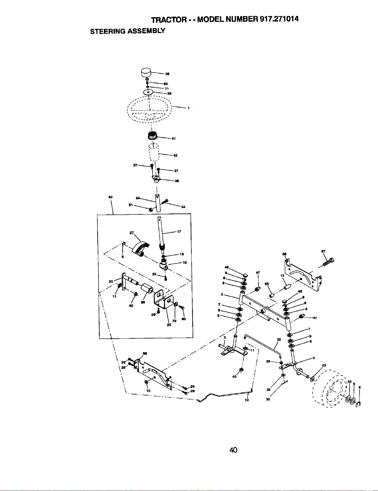
TRACTOR - - MODEL NUMBER 917.271014
STEERING ASSEMBLY
"--11--(13
-39
' •...... _...... J ;_ 1
41
,"----_ 42
44
4O
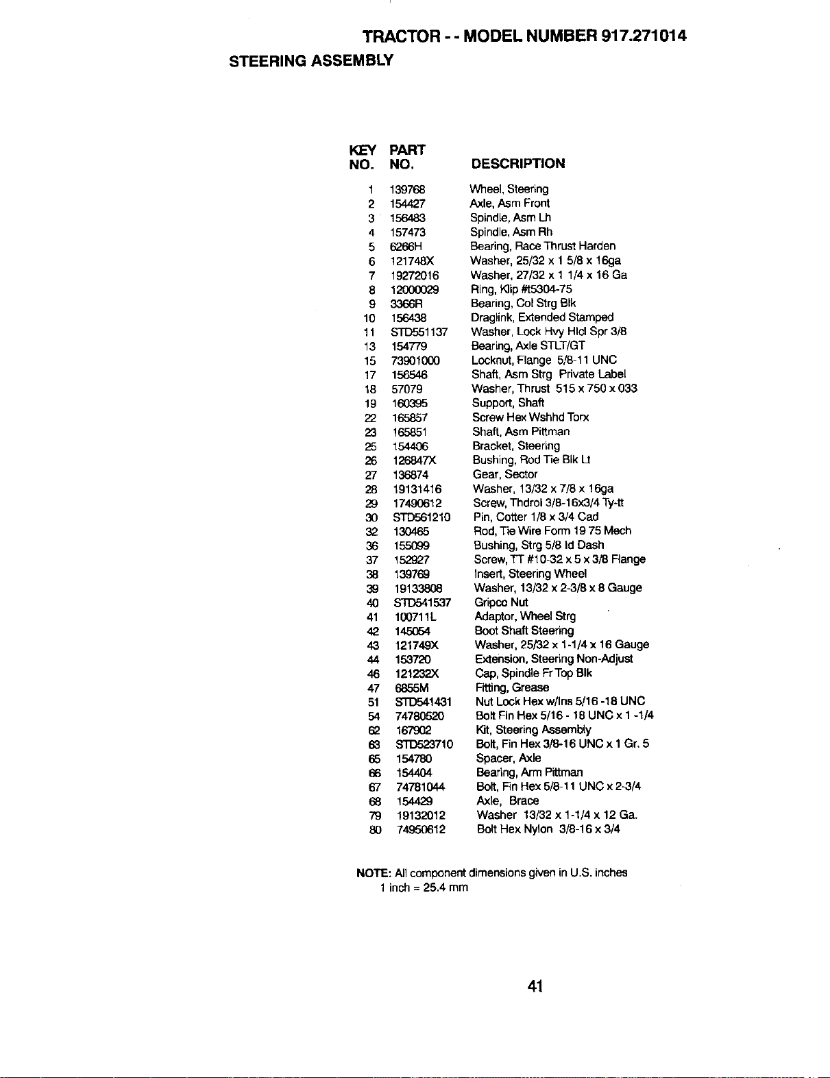
TRACTOR - - MODEL NUMBER 917.271014
STEERING ASSEMBLY
KEY PART
NO. NO. DESCRIPTION
1 139768
2 154427
3 156483
4 157473
5 6266H
6 121748X
7 19272016
8 12000029
9 3366R
10 156438
11 STD551137
13 154779
15 73901000
17 156546
18 57079
19 160395
22 165857
23 165851
25 154406
26 126847X
27 136874
28 19131416
29 17490612
30 STD561210
32 13O465
36 155099
37 152927
38 139769
39 19133808
40 STD541537
41 100711L
42 145_:,4
43 121749X
44 153720
46 121232X
47 6855M
51 STD541431
54 74780520
62 167902
63 STD523710
65 154780
66 154404
67 74781044
68 154429
79 19132012
80 74950612
Wheel, Steering
Axle, Asm Front
Spindle, Asm Lh
Spindle,Asm Rh
Bearing, Race Thrust Harden
Washer, 25/32 x 1 5/8 x 16ga
Washer, 27/32 x 1 1/4 x 16 Ga
Ring, K]ip #t5304-75
Bearing, Col Strg BIk
Draglink, Extended Stamped
Washer, Lock Hvy Hlcl Spr 3/8
Bearing, Axle STLT/GT
Locknut, Flange 5/8-11 UNC
Shaft, Asm Strg Private Label
Washer, Thrust 515 x 750 x 033
Support, Shaft
Screw Hex Wshhd Torx
Shaft, Asm Pittman
Bracket, Steering
Bushing, Rod Tie BIk Lt
Gear, Sector
Washer, 13/32 x 7/8 x 16ga
Screw,Thdrol 3/8-16x3/4 Ty-tt
Pin, Cotter 1/8 x 3/4 Cad
Rod, Tie Wire Form 19 75 Mech
Bushing, Strg 5/8 Id Dash
Screw,TI #10-32 x 5 x 3/8 Flange
Insert, Steering Wheel
Washer, 13/32 x 2-3/8 x 8 Gauge
Gripco Nut
Adaptor,Wheel Strg
BootShaft Steering
Washer, 25/82 x 1-1/4 x 16 Gauge
Extension, Steering Non-Adjust
Cap, SpindleFrTop BIk
Fitting,Grease
Nut Lock Hex w/Ins5/16 -18 UNC
Belt Fin Hex 5/16 - 18 UNC x I -1/4
Kit,Steering Assembly
Belt, FinHex 3/84 6UNC x1 Gr.5
Spacer, Axle
Beadng, Arm Plttmec
Belt, FinHex 5/8-11 UNC x 2-3/4
Axle, Brace
Washer 13/32 x 1-1/4 x 12 Ga.
Bolt Hex Nylon 3/8-16 x 3/4
NOTE: Allcomponent dimensions given in U.S. inches
1 inch= 25.4 mm
41
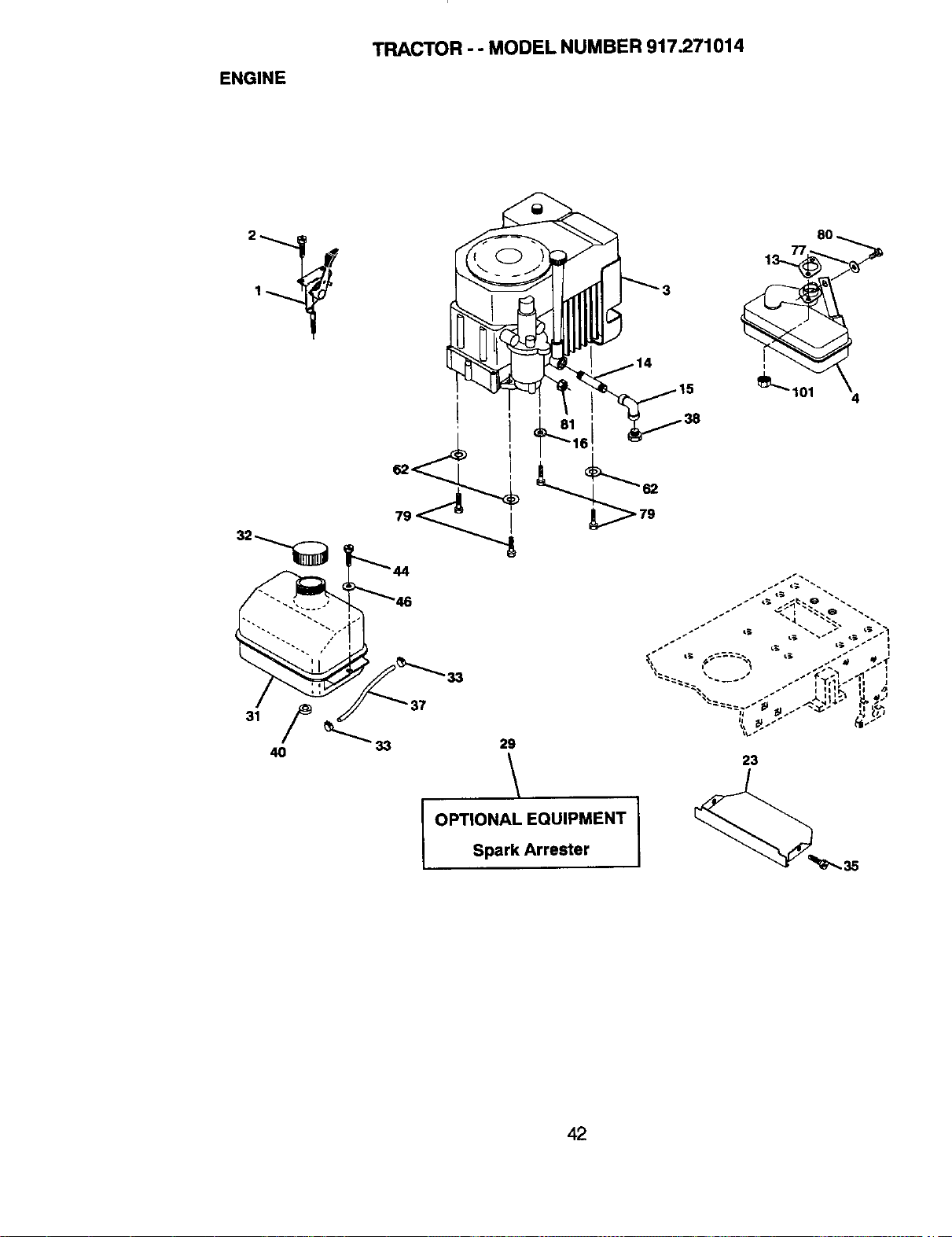
ENGINE
TRACTOR - - MODEL NUMBER 917.271014
2 80
29
\
OPTIONAL EQUIPMENT I
Spark Arrester
I _ _ "_ _e _
I p_ _, _;, _ I
23
42
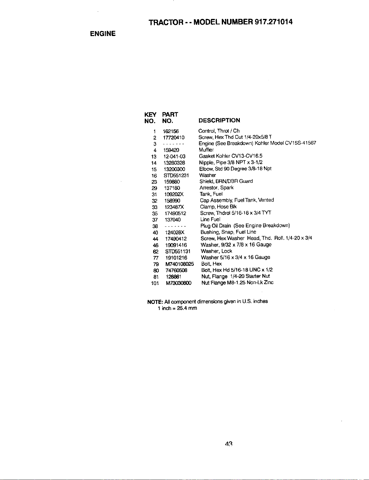
ENGINE
TRACTOR - - MODEL NUMBER 917.271014
KEY PART
NO. NO. DESCRIPTION
1 162156
2 17720410
3
4 159420
13 12-041-03
14 13280328
15 13200300
16 STD551231
23 15988O
29 137180
31 109202X
32 158990
33 123487X
35 17490512
37 137040
38 .......
40 124028X
44 17490412
46 lg091416
62 STD551131
77 19101216
79 M74010e_25
80 74760508
81 128861
101 M73030800
Control, Throt / Ch
Screw, HexThd Cut 1/4-20x5/8 T
Engine (See Breakdown) Kohler Model CV15S-41567
Muffler
Gasket Kohler CV13-CV16.5
Nipple,Pipe 3/8 NPT x 3-1/2
Elbow, Std 90 Degree3/6-18 Npt
Washer
Shield, BRN/DBR Guard
Arrestor, Spark
Tank, Fuel
Cap Assembly,FuelTank,Vented
Clamp,Hose B[k
Screw,Thdrol 5/16-18 x 3/4 TYT
Line Fuel
PlugOil Drain (See Engine Breakdown)
Bushing, Snap, Fuai Line
Screw, Hex Washer Head, Thd. RoU.1/4-20 x 3/4
Washer, 9/32 x 7/8 x 16 Gauge
Washer, Lock
Washer 5/16 x 3/4 x 16 Gauge
Bolt, Hex
Bolt, Hex Hd 5/16-18 UNC x 1/2
Not, Flange 1/4-20 Starter Nut
Nut Flange M8-1.25 Non-Lk Zinc
NOTE: All componentdimensionsgivenin U.S.inches
1inch = 25.4 mm
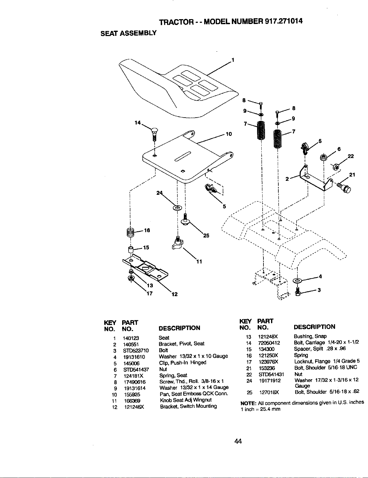
TRACTOR - - MODEL NUMBER 917.271014
SEATASSEMBLY
PART
NO. NO.
1 140123
2 140551
3 STD523710
4 19131610
5 145OO6
6 STD541437
7 124151X
8 17490616
9 1913_614
10 155925
11 166_
12 121246X
KEY PART
DESCRIPTfON NO. NO. DESCRIPTION
Seat 13 121248X
Bracket, Pivot, Seat 14 72050412
Bolt 15 13430O
Washer 13/32 x 1x 10 Gauge 16 121250X
Clip, Push-In Hinged 17 123976X
Nut 21 153236
SDring,Seat 22 ST[To41431
Screw,Thd., Roll 3/8-16 x 1 24 19171912
Washer "f3/3"2x "fx 14 Gauge
Pan, Seat EmbossQCK Conn. 25 t27018X
KnobSeat AdjWingnut
Bracket,SwitchMounting
Bushing,Snap
Bolt,Cardage 1/4-20 x 1-1/2
Spacer, Split .28 x .96
sprig
Locknut,Flange 1/4 Grade !
Bolt,Shoulder 5/16-t8 UNC
Nut
Washer 17/32 x 1-3/16 x 12
Gauge
Bolt,Shoulder 5/16-18 x .62
NOTE: All componentdimensionsgivenin U.S. inch,
1inch = 25.4 mm
44
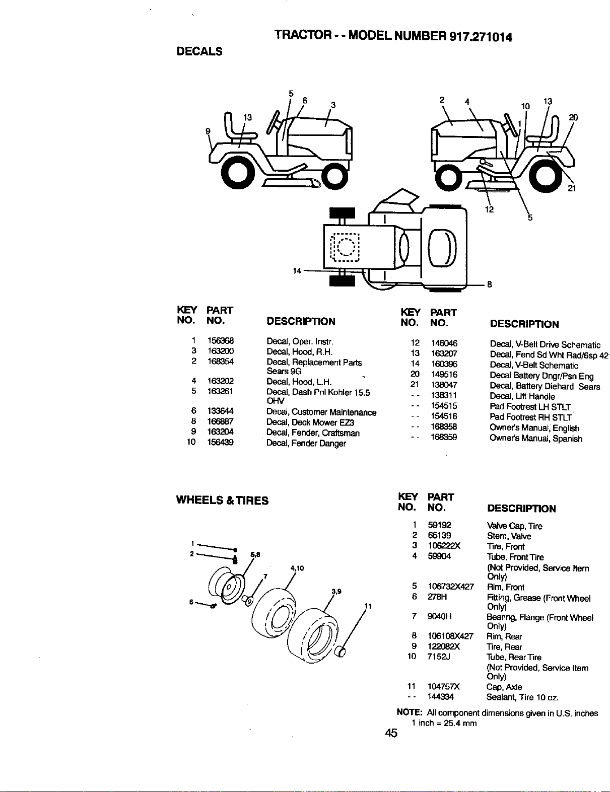
DECALS
TRACTOR - - MODEL NUMBER 917.271014
6 3
4
12
13
10
20
KEY
NO.
1
3
2
4
5
6
8
9
10
PART
NO.
156368
16320O
168354
163202
163261
133644
166887
1632O4
156439
KEY PART
DESCRIPTION NO. NO.
Decal,Ober. InStr. 12 146046
Decal, Hood,R.H. 13 163207
Decal,ReplacementParts 14 160396
Sears 9G 20 149516
Decal, Hood,LH. 21 138047
Decal, Dash Phi Kohler15.5 - - 138311
OHM - - 154515
Decal,Customer Maintenance - - 154516
Decal, Deck Mower EZ3 - - 168358
Decal, Fender,Craftsm_m - - 168359
Decal,FenderDanger
DESCRIPTION
Decal,V-Belt DriveSchematic
Decal,Fend SdWht Rad/6sp
Decal,V-BeltSchematic
Decal BatteryDngdPsn Eng
Decal, Battery Diehard Sears
Decal, LiftHandle
PadFootrestLH STLT.
Pad FootrestRH STLT
Owners Manual,English
Owners ManuaJ,Spanish
WHEELS &TIRES
4,10
11
KEY PART
NO. NO. DESCRIPTION
1 59192 ValveCap, 1ire
2 65139 Stem,Valve
3 106222.)( "13re,Front
4 59904 Tube,FrontTire
(NotProvided,ServiceItem
Only)
5 106732X427 Rim, Front
6 278H Fitting, Grease (FrontWheel
Only)
7 9040H Bearing,Flange(FrontWheel
Only)
8 106108X427 Rim,Rasz
9 122062)( "13re,Rear
10 7152J Tube,RearTite
(Not Provided, Service Item
Only)
11 104757X Cap, Axle
- - 144334 Sealant, Tire 10 oz.
NOTE: All_omponent dimanstons9ivan in U.S. inch.as
1 inch = 25.4 mm
45
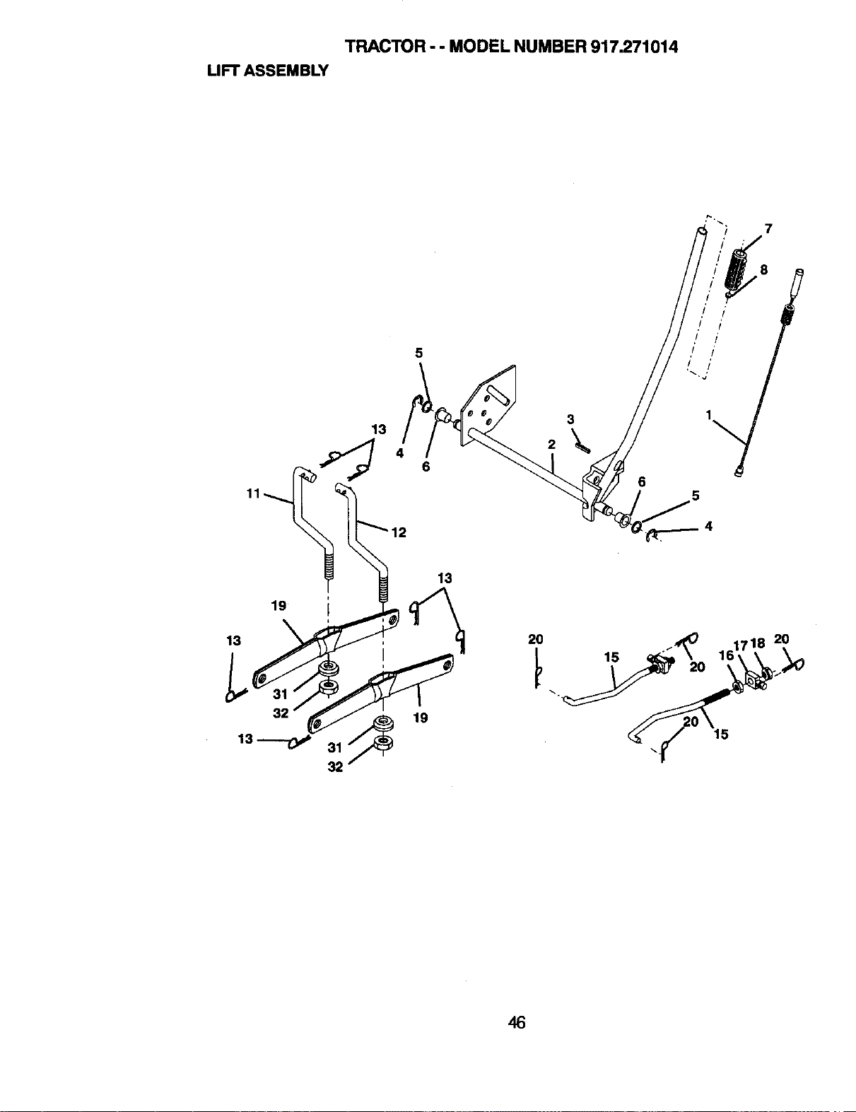
TRACTOR- - MODEL NUMBER 917.271014
LIFT ASSEMBLY
7
5
2
6
./ /'
,/ t'
i i
! J
20
15
20
,16
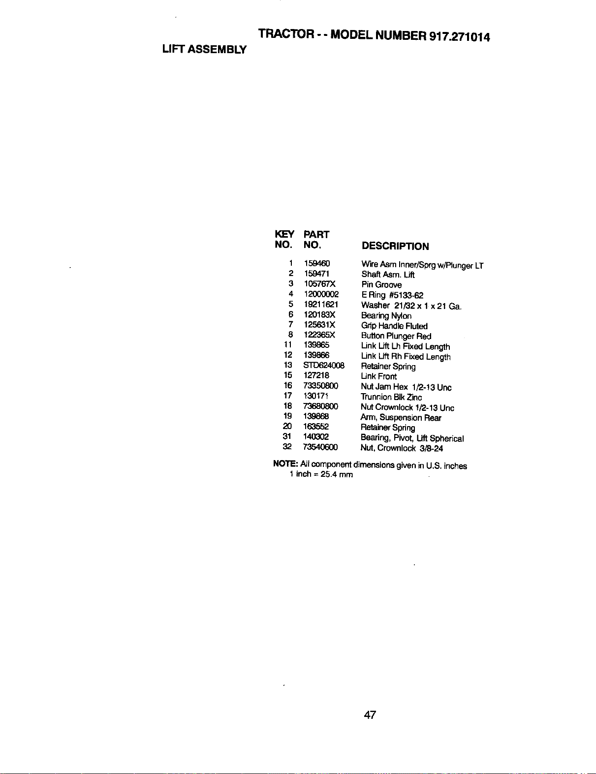
TRACTOR - - MODEL NUMBER 917.271014
LIFT ASSEMBLY
KEY PART
NO. NO, DESCRIPTION
1 159460 WireAsm InneriSprgw/PlungerLT
2 159471 ShaftAsm. Lift
3 105767X PinGroove
4 12000002 ERing #5133-62
5 19211621 Washer 21/32x lx21Ga.
6 120183X BearingNylon
7 125631X GripHandleRuted
8 122"365X ButtonPlungerRed
11 139865 LinkLiftLh Fixed Length
12 139866 Link Lift Rh Fixed Length
13 S'rO6240(_ RetainerSpring
15 127218 Unk Front
16 733,50800 NutJamHex 1_-!3Unc
17 130171 TrunnionBIkZinc
18 73680800 Nut Crownlock1#2-13Unc
19 13_868 Arm, SuspensionRear
20 163552 RetainerSpring
31 140302 Bearing,Pivot, Uft Spherical
32 73540600 Nut, Crownlock 3/8-24
NOTE: All componentdimensions givenin U.S. inches
1inch = 25.4 mm
47
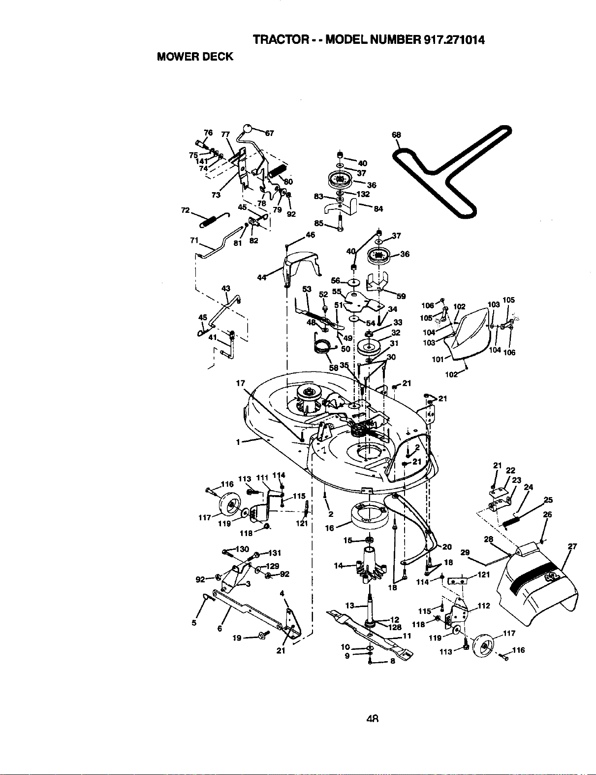
MOWER DECK
TRACTOR - - MODEL NUMBER 917.271014
76
17
36
5
116 113 111 11_
118
4
\
6
21
16
13----
10_
9_"
21
22
29
28
27
z_
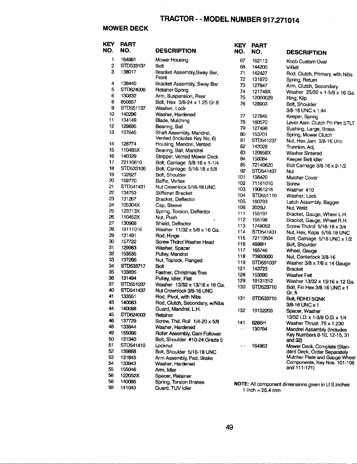
MOWERDECK
TRACTOR - - MODEL NUMBER 917.271014
KEY PART
NO. NO.
1 164961
2 STD533107
3 138017
4 138440
5 STD624008
6 130832
8 850857
9 STD551137
10 140296
11 134149
12 129885
13 137645
14 128774
15 110485X
16 140329
17 72110610
18 S'TD6&3106
19 132827
20 159770
21 STD541431
22 134753
23 131267
24 105304X
25 123713X
26 110452)(
27 130968
28 19111016
29 131491
30 157722
31 129963
32 153535
33 137266
34 STD533717
35 133835
36 131494
37 STO551(_7
40 STD541437
41 133551
43 14O083
44 14O088
45 STD6240(_
46 137729
48 133944
49 155066
50 131340
51 STD541410
52 139888
53 131845
54 133943
55 155O46
56 122052X
58 140(386
59 141043
KEY PART
DESCRIPTION NO. NO.
Mower Housing 67 162113
Bolt 68 144200
Bracket Assembly,Sway Bar, 71 142427
Front 72 131870
Bracket Assembly, Sway Bar 73 127847
Retainer Spring 74 121748X
Arm, Suspension, Rear 75 12000029
Bolt, Hex 3/8-24 x 1.25 Gr8 76 128903
Washer, Lock
Washer, Hardened 77 127845
Blade, Mulching 78 160570
Beahng, Ball 79 127498
Shaft Assembly, Mandrel, 80 153701
Vented (Includes Key No. 6) 81 S'T'D541237
Housing, Mandrel, Vented 82 142028
Bearing, Ball, Mandrel 83 120958X
Stripper,VentedMower Deck 84 156084
Bolt, Carriage 3/8-16 x 1-1/4 85 72140620
Bolt, Carriage 5/16-18 x 5/8 92 STD541437
Bolt, Shoulder 101 136420
Baffle, Vortex 102 71161010
NutCrownlock 5/16-18 UNC 103 19061216
Stiffener Bracket 104 STD551110
Bracket, Deflector 105 160793
Cap, Sleeve 106 2029J
Spring, Torsion, Deflector 111 155197
Not, Push 112 155198
Shield, Deflector 113 1749052
Washer 11/32x5/3x16Ga. 114 STD541431
Red, Hinge 115 72110504
Screw ThdrolWasher Heed 116 4898H
Wesher, Spacer 117 165746
Pulley, Mandrel 118 73930600
Not, Toplock, Flanged 119 STD5510_37
Bolt 121 143723
Fastner, Christmas Tree 128 153,390
Pulley,Idler, Flat 129 19131312
Washer 13/32 x 13/16 x 16 Ga. 130 STD523710
Not Crownlack3/8-16 UNC
Red, Pivot,with Nibs 131 S'T_710
Rod, Clutch, Secondary,w/Nibs
Guard, Mandrel,LH. 132 19132203
Retainer
Screw,Thd. Roll 1/4-20 x 5/8 141 6266H
Washer,Hardened - - 130794
Roller Assembly,CamFollower
Bolt,Shoulder #10-24 Grade 5
Locknut - - 164963
Bolt, Shoulder 5/16-18 UNC
Arm Assembly, Pad, Brake
Washer, Hardened
Arm, Idler
Spacer, Retainer
Spring, Torsion Brakes
Guard, TUV Idler
DESCRIPTION
KnobCustom Oval
V-Belt
Rod,Clutch, Primary,with Nibs
Spring, Retum
Arm, Clutch, Secondary
Washer 25/32 x 1-5/8 x 16 Ga
Ring,Klip
Bait, Shoulder
3/8-16 UNC x 1.44
Keeper,Spring
LeverAsm. Clutch PriPIm STLT
Bushing, Large, Brass
Spring, Mower Clutch
Nut, Hex Jam 3/8-16 Unc
Trunnion,Adj.
Washer Sintered
Keeper Bait Idler
Bolt Carriage 3/8-16 x 2-1/2
Nut
MulcherCover
Screw
Washer #10
Washer, Lock
Latch Assembly, Bagger
Nut,Weld
Bracket, Gauge, Wheel LH.
Bracket, Gauge, Wheel R.H.
Screw Thdrol 5/16-18 x 3/4
NOt,Hex, Keps 5/16-18 UNC
Bolt, Carriage 5/16 UNC x 1/2
Bolt, Shoulder
Wheel, Gauge
Nut,Centerlock 3/8-16
Washer 3/8 x 7/8 x 14 Gauge
Bracket
Washer Felt
Washer 13/32 x 13/16 x 12 Ga.
Bait, FinHex 3/3-16 UNC x 1
Gr.5
BOP,,RDHD SQNK
3/3-16 UNCx 1
Spacer, Washer
13/32 I.D.x 1-3/80.D. x 1/4
Washer Thrust .75 x 1.230
Mandrel Assembly (Includes
Key Numbers 8-10, 12-15,31
and32)
Mower Deck, Complete (Stan-
dard Deck, Order Separately
MulcherPlate andGauge Wheel
Components, Key Nus. 101-106
and 111-121)
NOTE: All component dimensions givenin U.S.inches
1 inch = 25.4 mm
49
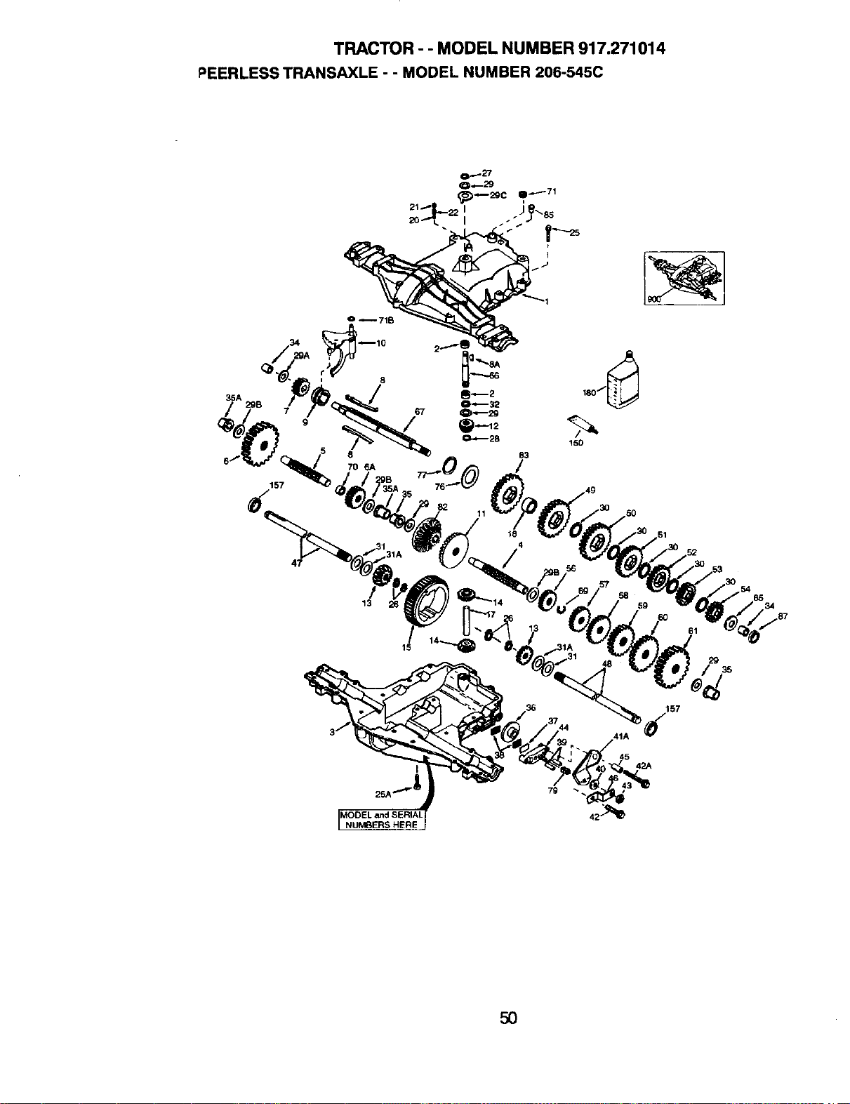
TRACTOR - - MODEL NUMBER 917.271014
_EERLESS TRANSAXLE - - MODEL NUMBER 206-545C
35A
/
157
8
7O 6A
1
83
11
47
13
34
29
36 157
45
42A
NUMBERS HERE
5O
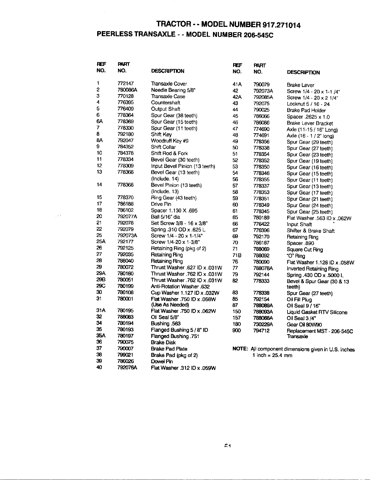
TRACTOR - - MODEL NUMBER 917.271014
PEERLESS TRANSAXLE - - MODEL NUMBER 206-545C
REF PART REF PART
NO. NO. DESCRIPTION NO. NO. DESCRIPTION
1 772147 TransaxleCover 41A 790079 Brake Lever
2 780086A Needle Bearing 5/8" 42 792073A Screw 1/4 - 20 x 1-1/4"
3 770128 Transaxle Case 42A 792085A Screw 1/4 - 20 x 2 1/4"
4 776395 Countershaft 43 792075 Leeknut 5/ 16 - 24
5 776409 Output Shaft 44 790025 Brake Pad Holder
6 778364 Spur Gear (38teeth) 45 786066 Spacer .2625 x 1.0
6A 778369 Spur Gear (15teeth) 46 786086 Brake Lever Bracket
7 778330 Spur Gear (11teeth) 47 774690 Axle (11-15 / 16" Long)
8 792180 Shift Key 48 774691 Axle (16- 1/2" long)
8A 792047 Woodruff Key #9 49 778356 Spur Gear (29 teeth)
9 784352 Shift Collar 50 778338 Spur Gear (27teeth)
10 784378 Shift Rod & Fork 51 778354 Spur Gear (23teeth)
11 778334 Bevel Gear (30 teeth) 52 778352 Spur Gear (19teeth)
12 7783(}9 Input Bevel Pinion (13teeth) 53 778350 Spur Gear (16 teeth)
13 778368 Bevel Gear (13 teeth) 54 778346 Spur Gear (15 teeth)
(Include. 14) 56 778355 Spur Gear (11teeth)
14 778368 Bevel Pinion (13 teeth) 57 778337 Spur Gear (13 teeth)
(Include. 13) 58 7783.53 Spur Gear (17 teeth)
15 778370 Ring Gear (43teeth) 59 778351 Spur Gear (21 teeth)
17 786188 Drive Pin 60 778349 Spur Gear (24teeth)
18 786102 Spacer 1.130 X .695 61 778345 Spur Gear (25teeth)
20 792077A Ball 5/16" dia 65 780189 FlatWasher .563 ID x .062W
21 792078 Set Screw 3/8 - 16 x 3/8" 66 776422 Input Shaft
22 792079 Spring .310 OD x .625 L 67 776396 Shifter & Brake Shaft
25 792073A Screw 1/4 - 20 x 1-1/4" 69 792170 Retaining Ring
25A 792177 Screw 1/4-20 x 1-3/8" 70 786187 Spacer .890
26 792125 Retaining Ring (pkg of 2) 71 788069 Square CutRing
27 7920_5 RetainingRing 71B 788092 "O" Ring
28 788040 Retalr,JngRing 76 780(_0 Fiat Washer 1.128 ID x .058W
29 780072 Thrust Washer .627 ID x .031W 77 788078A InvertedRetaining Ring
29A 780160 Thrust Washer .762 ID x .031W 79 792144 Spring .430 OD x .5000 L
29B 780(351 ThrustWasher .762 ID x .03!W 82 T/8333 Bevel &Spur Gear (30 & 13
29C 780199 Anti-Rotetion Washer .632 teeth)
30 7801(38 Cup Washer 1.127 IDx .032W 83 778338 SpurGear (27 teeth)
31 780001 FlatWasher .750 ID x .056W 85 792154 Oil FillPlug
(Use As Needed) 87 788089A Oil Seal 9/ 16"
31A 780195 FlatWasher .750 ID x .062W 150 788093A Uquid Gasket R'FVSilicone
32 _ Oil Seal 5/8" 157 788068A OilSeal 3/4"
34 780194 Bushing.563 180 730229A GearOil80W90
36 78019_3 FlangedBushing5 / 8" ID 900 794712 ReplacementMST- 266-545C
_oA 780197 F_nged Bushing.751 Transaxle
36 790075 Brake Disk
37 790007 Brake Pad Plate NOTE: _t componentdimensionsgivenin U.S. inches
38 799_1 Brake Pad (pkgof2) 1 inch = 25.4 rnm
39 786026 Dowe{Pin
40 792076A FlatWasher .312 ID x .059W
_q
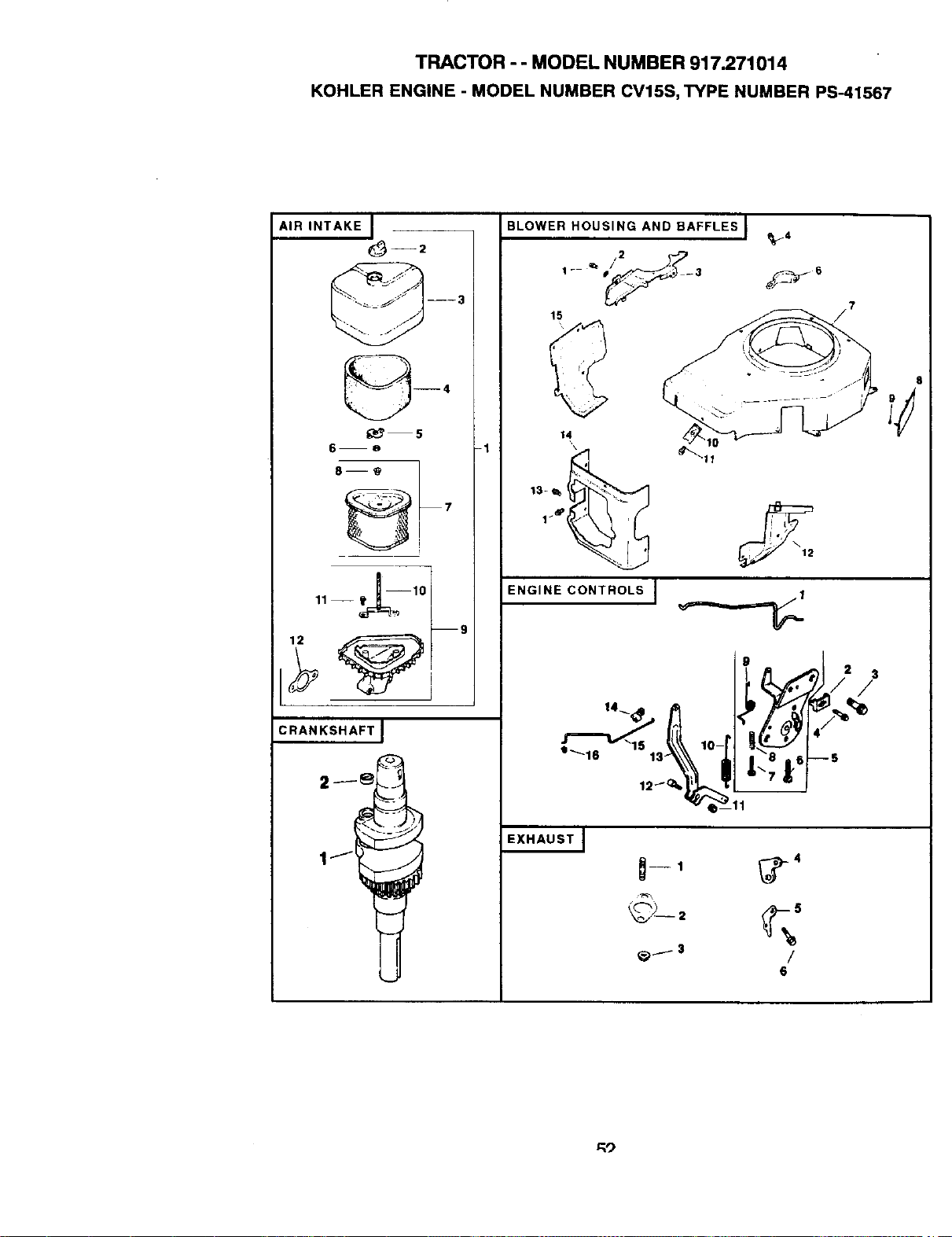
TRACTOR - - MODEL NUMBER 917.271014
KOHLER ENGINE - MODEL NUMBER CV15S, TYPE NUMBER PS-41567
AIR INTAKE I
_ 5
6--a
11 -- ___--10
--g
CRANKSHAFT I
BLOWER HOUSING AND BAFFLES J
_4
15
-1
ENGINE CONTROLS J
EXHAUST]
_--1 _)-4
6
8
3
/
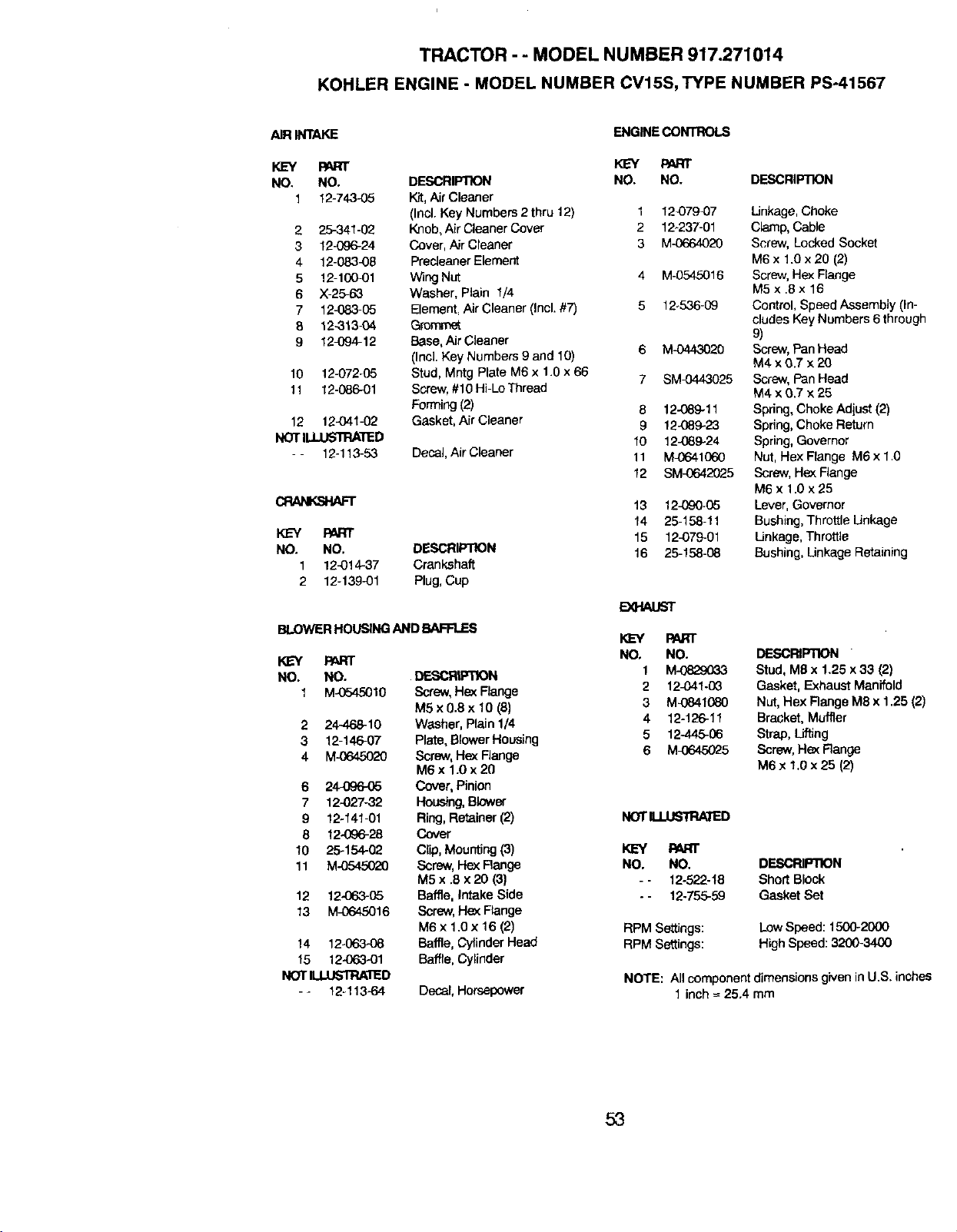
TRACTOR - - MODEL NUMBER 917.271014
KOHLER ENGINE - MODEL NUMBER CV15S, TYPE NUMBER PS-41567
AIRINTAKE
KEY PART
NO, NO.
1 t2-743_5
2 25-341-02
3 12-_36-24
4 12-083-08
5 12-100-01
6 X-25_3
7 12_83-05
8 12-313-04
9 12-094-12
t0 12-072-05
11 t2-086_1
12 12,041-02
NOTILLUSll:IA'RED
-- 12-113-53
DESCRIPTION
Kit,AirCleaner
(Incl. Key Numbers2 thru12)
Knob,AirCleanerCover
Cover,Air Cleaner
Predeaner Element
W_ngNut
Washer, Plain 1/4
Element, Air Cleaner (Incl. #7)
G_ommst
Base,Air Cleaner
(Incl. Key Numbers 9 and 10)
Stud, Mntg Plate M6 x 1.0 x 66
Screw,#10 Hi-Lo Thread
Forming(2)
Gasket, Air Cleaner
Decal, Air Cleaner
CRANKSHAFT
KEY PART
NO. NO. DESCRIPTION
1 12-014-37 Crankshaft
2 12-139-01 Plug,Cup
BLOWERHOUSINGAND BAF'R.ES
KL_Y PARr
NO. NO. DF..SCRUUqlON
1 M-0545010 Screw,He_ Flange
M5 x 0.8 x 10 (8)
2 24-468-10 Washer, Plain 1/4
3 12-146-07 Plate, BlowerHousing
4 M-0645020 Screw,He_ Range
M6 x 1.0 x 20
6 24-096-(_ Cover, Pinion
7 12-027-32 Housing,Blower
9 12-141-01 Ring,Retainer(2)
8 12-096-28 Cover
10 25-154-02 Clip, Mounting (3)
11 M-0545020 Screw,Hex Range
M5 x .8 x 20 (3)
12 12-063-05 Baffle, Intake Side
13 M-0645016 Screw, He¢<Flange
M6x 1.0x 16 (2)
14 12-_ Baffle,Cylinder Head
15 12-O63-01 Baffle,Cylinder
NOTILUJSll:IA/ED
- - 12-113-64 Decar,Horsepower
ENGINECONTROLS
KEY PART
NO. NO. DESCRIPTION
1 t2_79,07 Linkage, Choke
2 12_237-01 Clamp, Cable
3 M_o64020 Screw, Locked Socket
M6 x 1.0 x 20 (2)
4 M-0545016 Screw,Hex Flange
M5 x .8 x 16
5 12o536-09 Control, Speed Assembly (in-
cludesKey Numbers6 through
9)
6 M-0443020 Screw,PanHead
M4xO.7 x20
7 SM_443025 Screw, PanHead
M4xO.7 ×25
8 12-089-1t Spring,ChokeAdjust(2)
9 12-089-23 Spring,ChokeReturn
10 t2_89-24 Spring,Governor
1t M_o41060 Nut,Hex Flange M6 x1.0
12 SM_c42025 Screw,Hex Flange
M6 x 1.0 x 25
t3 12-090-05 Lever,Governor
14 25-158-11 Bushing,Throttle Linkage
15 12-079-01 Linkage, Throttle
16 25-158-08 Bushing, Linkage Retaining
E)04AUST
PART
NO, NO. DESCRIPTION
1 M-0_29G33 Stud, M8 x 1.25 x 33 (2)
2 12-041-0G Gasket, Exhaust Manifold
3 M-0841080 Nut, Hex Range M8 x t.25 (2)
4 12-126-11 Bracket,Muffler
5 12-445-06 Strap, Lifting
6 M_645025 Screw,Hex Range
M6 x 1.0x25 (2)
NOTII.LUSTR/OED
KEY PART
NO. NO. DESCRIPllON
- - 12-522-18 Short Block
- - 12-755-59 Gasket Set
RPM Settings:
RPM Settings:
Low Speed: 1500-2000
HighSpeed:3200-3400
NOTE: All componentdimensions given inU.S. inches
1 inch-- 25.4 mm
53
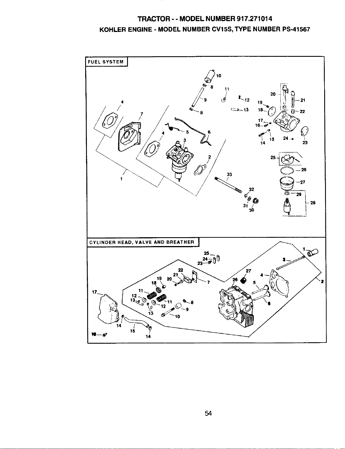
TRACTOR - - MODEL NUMBER 917.271014
KOHLER ENGINE - MODEL NUMBER CV15S, TYPE NUMBER PS-41567
FUEL SYSTEM j
1o
6
CYLINDER HEAD, VALVE AND BREATHER I
25
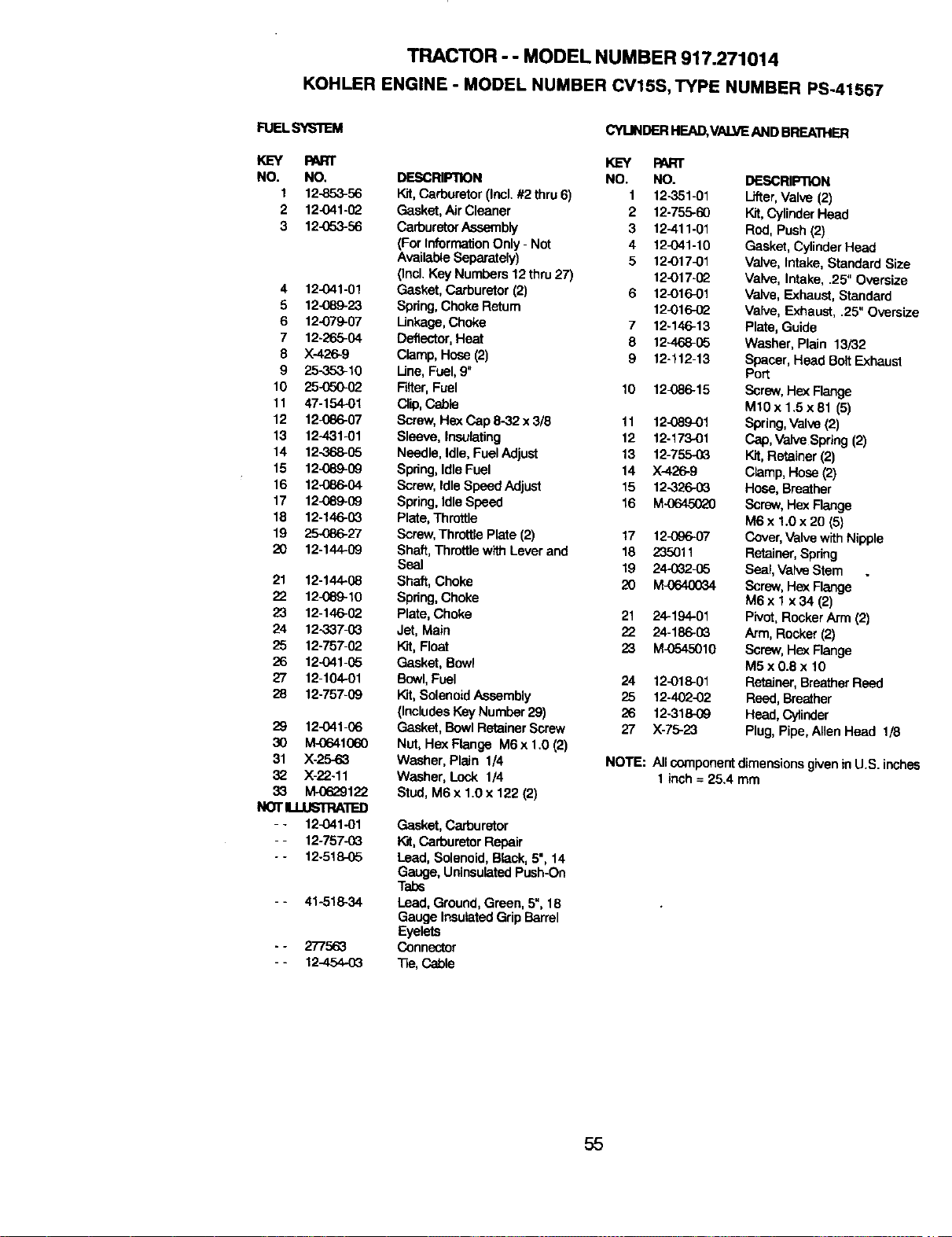
TRACTOR - - MODEL NUMBER 917.271014
KOHLER ENGINE - MODEL NUMBER CV15S, TYPE NUMBER PS-41567
FUELSYS'I_M
CYI..INDERHEAD,VALVEAND BREATHER
KEY RNRT t(_=Y PART
NO. NO. DESCRIPTION NO. NO. DESCRIPTION
1 12-853-56 Kit,Carburetor (Incl.#2 thru6) 1 12-351-01 Lifter,Valve (2)
2 12-041-02 Gasket, AirCleaner 2 12-755-60 Kit,Cylinder Head
3 12_o3-56 CarburetorAssembly 3 12-411-01 Rod, Push(2)
(ForInformationOnly - Not 4 12_41-10 Gasket, CylinderHead
AvailableSeparately) 5 12-017-01 Valve, Intake, Standard Size
(thcl.Key Numbers 12 thru27) 12-017-02 Valve, Intake, .25" Oversize
4 12_41-01 Gasket, Carburetor (2) 6 12-016_1 Valve, Exhaust, Standard
5 12-089,23 Spring,Choke Return 12_)16-02 Valve, Exhaust, .25" Oversize
5 12-079-07 Linkage,Choke 7 12-146-13 Plate, Guide
7 12-265-04 Deflector,Heat 8 12-468-05 Washer, Plain 13/32
8 X-426-9 Clamp,Hose(2) 9 t2-t12-13 Spacer, Head BoltExhaust
9 25,353_I0 Line,Fuel,9" Port
10 25-(T00-52 Filter,Fuel 10 12_86-15 Screw,He:<Flange
11 47-154.-01 Clip,Cable Mt0x 1.5x81 (5)
12 12-086-07 Screw, He;<Cap 8-32 x 3/8 11 12-089_1 Spring,Valve(2)
13 12-431-01 Sleeve, Insulating 12 12-173-01 Cap, VaiveSpdng (2)
14 12-368-05 Needle, Idle,Fuel Adjust 13 12-755-03 Kit,Retainer (2)
15 12-089-09 Spring,IdleFuel 14 XA26-9 Clamp,Hose(2)
16 12-086-04 Screw, IdleSpeed Adjust 15 12-326-03 Hose,Breether
17 12_)89-09 Spring,IdleSpeed 16 M-0645020 Screw,HexFlange
18 12-146-0_ Plate,Throttle M6 x 1.0 x 20 (5)
19 25086-27 Screw,ThrottleRate (2) 17 12-0_o-07 Cover,ValvewithNipple
20 12-144-09 Shaft,Throttlewith Lever and 18 235011 Retainer, Spring
Seal 19 24-032-05 Seal,Vah_eStem
21 12-144-08 Shaft, Choke 20 M-0640034 Screw, HexFlange
22 12_)89-t0 Spdng,Choke M6 x 1 x 34 (2)
23 12-146-02 Plate, Choke 21 24-194-01 Pivot,RockerArm (2)
24 12-33703 Jet, Main 22 24-186-03 Arm, Rocker (2)
25 12-757-02 Wit,Float 23 M_545010 Screw, H_ Flange
26 12-041-05 Gasket, Bowl M5 x 0.8 x 10
27 12-104-01 Bowl,Fuel 24 12-018-01 Retainer,BreatherReed
28 12-757-09 }_t, SolenoidAssembly 25 12-402-02 Reed,Breather
(IncludesKeyNumber 29) 26 12-318-09 Head, Cylinder
29 12-041-06 Gasket, Bowl Retainer Screw 27 X-75-23 Plug, Pipe, Allen Head 1/8
30 M-0641060 Nut, HexFtange M6x1.0(2)
31 X-25..63 Washer, Plain 1/4 NOTE: All componentdimensions given in U.S. inches
32 X-22-11 Washer, Lock 1/4 1inch = 25.4 mm
33 M-0629122 Stud, M6 x 1.0 x 122 (2)
NOTIJ.USTRAIT=D
- - 12_41-01 Gasket, Carburetor
- - 12-75703 I_t, Carburetor Repair
- - 12-51_05 Lead, Solenoid, Black,5", 14
Gauge, UninsulatedPush-On
Tabs
- - 41-51834 Lead, Ground,Green, 5",18
Gauge InsulatedGripBarrel
Eyelets
- - 277563 Connector
- - 12-454-03 "13e,Cable
55
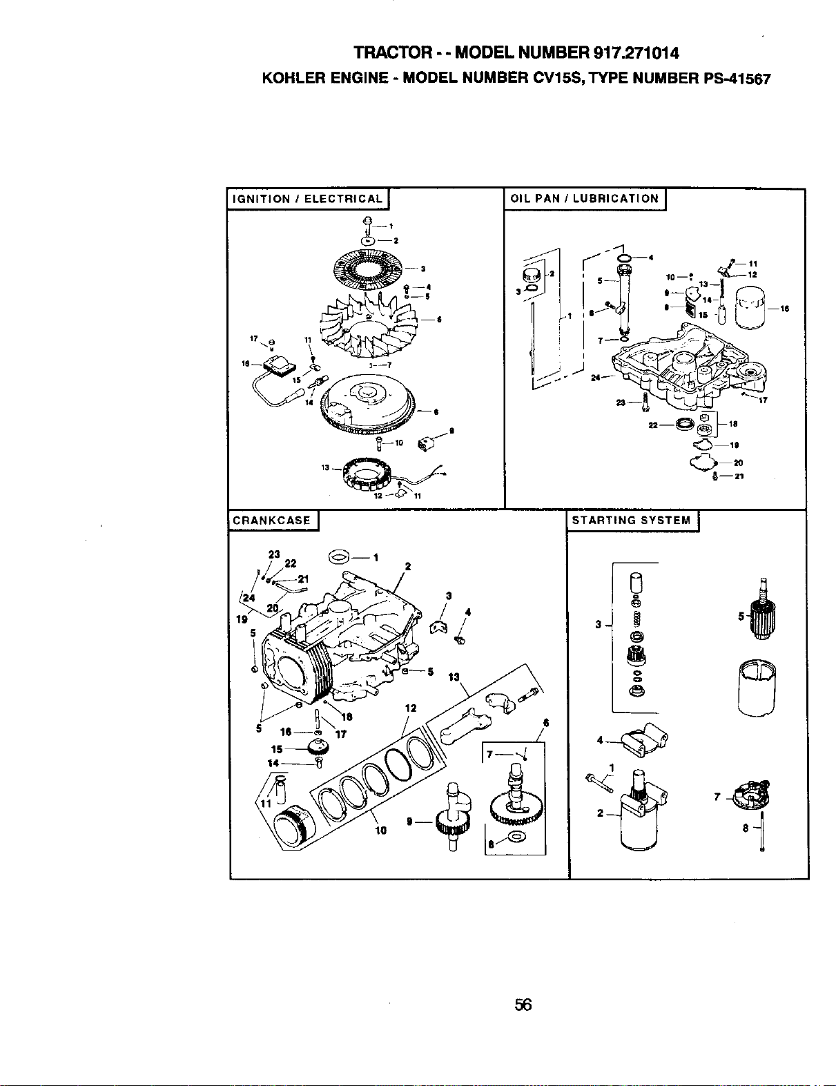
TRACTOR - - MODEL NUMBER 917.271014
KOHLER ENGINE - MODEL NUMBER CV15S, TYPE NUMBER PS-41567
IGNITION I ELECTRICAL]
9--'
Q--2
OIL PAN / LUBRICATION I
CRANKCASEJ
23
19
STARTING SYSTEM J
@
o.
o
56
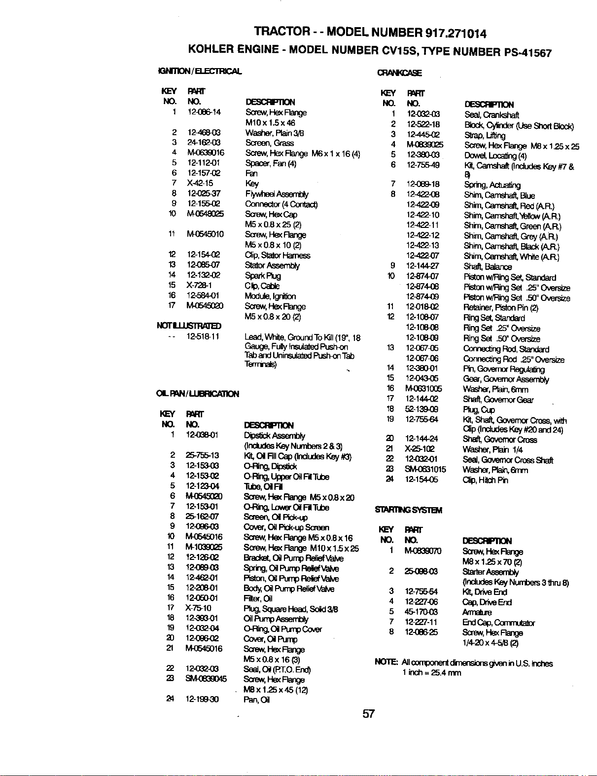
TRACTOR - - MODEL NUMBER 917.271014
KOHLER ENGINE - MODEL NUMBER CV15S, TYPE NUMBER PS-41567
IGNmON/a.ECrRICAL
KEY P/_tr
NO. NO.
1 12-086-34
2 12-4684_
3 24-162-(3G
4 M-0639016
5 12-11201
6 12o157_2
7 X-4,?.-15
8 12-02537
9 12-155-(_
10 MO548Q25
11 M.0545010
12 12q54._2
13 12-(385.O7
14 12-13_
15 X-728-1
16 12-584.O1
17 M-05450_0
NOT_
-* 12-518-11
OILPAN/_
mRl"
NO. NO,
1 124388-01
2 25-756-13
3 12-153.03
4 12-153432
5 12-123-04
6
7 12-153-01
8 25-162-07
9 12_96..68
10 M..0545016
11 Mr1(_9025
12 12-126-62
!3 12-08903
14 12J,62-01
15 12-20801
16 12-05OO1
17 X-75-10
18 12_1
19 124_2-04
3) 12-066-(_
21 M-0545016
22 12-0_t-03
23 SM-0839045
24 12-19930
KEY PART
NO. NO.
Screw,HexF'eage 1 12_438
M10x 1.5x46 2 12-522-18
Wash_, PtaJn3/8 3 1241454_
Screen,Grass 4 M0839(]_5
Screw,l'-IexFlangeM6xlx16(4) 5 12.3804_
Spacer,Fan(4) 6 12-755-49
Fan
Key 7 124389-18
Flywheet/k._ 8 124_2-08
Connector(4 Cordact) 12422-69
Soew,HexCap 12J,22-10
M5 x0.8x 25 (2) 12-422-11
Screw,He_Flange 12J..22-12
M5 x 0.8x 10 (2) 12-422-13
Oiip,8tstor Hamem 12-422-07
St_torAs_ 9 12-144-27
Spa_ Rug 10 12-874._7
Cip, Cede 12-874.-08
Module,IgnilJon 12_174,-09
Screw,HexFlange 11 124318-02
M5 x0.8 x 20 (2) 12 12-1084)7
12-10808
Lead,White,GroundTo_1 (1£",18 12-108_9
Gauge,FuPyinsulated_ 13 124367435
TabandUninsu_a_dPushKxlTat} 12_67_6
T_ 14 12-,3804)1
15 12-04.3.O5
16 M.4_810(]5
17 12-144.-(_
18 52-139-09
19 12-755484
_ly 20 12-144-24
(IncludesKeyNumbers2 &3) 21 X-25-1(_
teat,OilFdlCap(IncludesKey#3) 22 12082-01
_, Oips_ m ,Slvl43681015
O-Ring,_ OilF| Tube 24 12-154-05
Tube,Oi RI
Soew,I-k_ FlangeM5x 0.8x 20
O-Ring,_ OilF-ClTube b'_I_R11NGSYb-'1131
Screen,OilPick-up
_, Oi_Pick-upScreen KEY
Screw,I--lexRangeM5x 0.8x 16 NO. NO.
Scre_,HexF_ M10xl.Sx25 1 M-0B39070
_ OilPumpReliefValve
Sprite,OilPumpP,er,iefva_ 2 25-0860S
Rston,O_PumpRertefVak,e
Body,OilPumpReliefValve 3 12-755-54
Filter,Oil 4 12-_7-06
Rug,SquareHead,Solid3/8 5 454 704_
OilPun_ Assembly 7 12-_7-11
O-Rng,OiPumpCover 8 12-m6-25
Cover,O_Pump
_,HexRange
M5 x0.Sx 16 (3)
se_,c_(m:,o.Eno)
Scr_,H_ F_ge
MSx 125x45 (12)
P_,Ol
DBSCflP]ION
Sea_,Crankshaf_
B_k,Cy_nder(UseSho_tB_k)
S_ab,_
Screw,Hex Flange M8x 1.25x 2_
Dowel,Loc_ng (4)
F.t,Camshat 0ndudesKey#7&
Shim,C,ar'nsaa&81ue
Shim,_ Red(.'&R.)
Shim,_ Yellow(A.R.)
Sh_, Camsha&Green(A.R.)
Shim,_ Grey(A.R.)
Shim,Camsha& Black(A.R.)
S_m, C_,emsh_VV_e p_R.)
Sh_ BaJance
Pistonw/RingSe_Standard
Pistonw/RingSet 25"Oversize
Pistonw/RingSet .50_Oversize
Retainer,PistonPin(2)
RingSet,Standard
RingSet 25" O_B_#_e
RingSet .50"Oversize
P_.,onnec_ngRod,Standard
Connec_ngRod ,25"Oversize
Gear,GovernorAssembly
Washer,Rain,6mm
Shatt,Govem<xGear
F_u_Oup
K.._t,Sha&GovernorCross,with
Qip (IndudesKey#20and 24)
Sh_ Gove_x C4oss
Washer,PbJn 1/4
Seal,_ CrossShaft
Wash_,Pta_enm
Cf_p,HighPin
DESCRP110N
Screw,t-k_
M8x 1.25x 70 (2)
s_r_
_eE_
NOTE: Allcomponent_ g_en inU.S.inches
1inch=25.4 mm
57

58

SUGGESTED GUIDE FOR SIGHTING SLOPES FOR SAFE OPERATION
I "-
SIGHTING
GUIDE
ONLY RIDE UP AND DOWN HILL,
NOT ACROSS HILL
/_ Operate your Tractor up and down the face of slopes (not I
I
greater than 15°), never acro_;s the face. Make turns gradu- I
_1_ ally to prevent tipping or loss of control. Exercise extreme J
caution when changing direction on slopes. I
I

For in-home major brand repair service:
Call 24 hours a day, 7 days a week
1-800-4-MY-HOME SM (1-800-469-4663)
Para pedir servicio de reparacibn a domicilio
1-800-676-5811
In Canada for all your service and parts needs call
Au Canada pour tout le service ou les pieces
1-800-665-4455
For the repair or replacement parts you need:
Call 6 am - 11 pm CST, 7 days a week
PartsDirect SM
1-800-366-PART (1-800-366-7278)
Para ordenar piezas con entrega a domicilio
1-800-659-7084
For the location of a Sears Parts and Repair Center
in your area:
Call 24 hours a day, 7 days a week
1-800-488-1222
For information on purchasing a Sears Maintenance
Agreement or to inquire about an existing Agreement:
Call 9 am - 5 pm, Monday - Saturday
1-800-827-6655
Home Central SM
168358 Rev. 1 08.05.99 RH/SV Printed in U.S.A