Loading ...
Loading ...
Loading ...
14 Specifications subject to change without notice. IM-40MHH-02
FINAL TUBING CHECK
IMPORTANT: Ensure certain factory tubing on the indoor unit
has not shifted during shipment. Ensure tubes are not rubbing
against each other or any sheet metal. Pay close attention to feeder
tubes, making sure wire ties on feeder tubes are secure and tight.
Drain Connections
Connect the drain line. The drain line must not have a trap anywhere
in its length, must pitch downwards, and must be insulated up to the
outside wall (see Fig. 27). By default, the drain hose is attached to the
left−hand side of unit (when facing the back of the unit). However, it
can also be attached to the right−hand side.
a. To ensure proper drainage, attach the drain hose on the
same side that your refrigerant piping exits the unit.
b. Attach a drain hose extension (purchased separately) to the
end of drain hose.
c. Wrap the connection point firmly with Teflon tape to
ensure good seal and to prevent leaks.
d. For the portion of the drain hose that will remain indoors,
e. Wrap it with foam pipe insulation to prevent condensation.
f. Remove the air filter and pour a small amount of water into
the drain pan to ensure that water flows from the unit
smoothly.
Plug the Unused Drain Hole
To prevent unwanted leaks you must plug the unused drain hole with
the rubber plug provided.
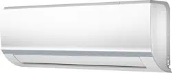
Fig. 27 — Proper Drain Hose Installation
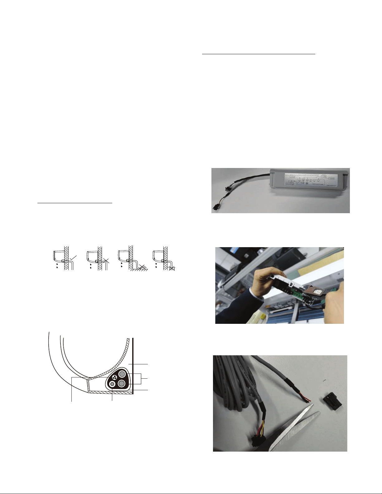
NOTE: For proper orientation of the refrigerant piping, electrical
cable and drain lines, refer to Fig. 28.
Fig. 28 — Bundle drain hose, refrigerant pipes, & signal cable
NOTE: For applications where gravity cannot be used for
drainage, a condensate pump accessory is available. Consult the
condensate pump Installation Instructions for more information.
WIRELESS REMOTE CONTROL
INSTALLATION
Mounting Bracket (if installed on the wall)
1. Use the two screws supplied with control to attach the mounting
bracket to the wall in a location selected by customer and within
operating range.
2. Install batteries in the remote control.
3. Place the remote control into the remote control mounting bracket.
NOTE: For remote control operation, refer to the unit Owner’s
Manual.
WIRED REMOTE CONTROLLER
INSTALLATION
For setup instructions, refer to the wired controller installation
manual.
1. Use the multi−function board supplied.
Fig. 29 — Multi Function Board
2. Use needle nose pliers to cut a hole on the multi-function board for
wiring.
Fig. 30 — Cut a hole on the multi-function board
3. Cut the female plug from the cable supplied with the wired remote
controller and strip the wires to connect to the adaptor board.
Fig. 31 — Cut the female plug and strip the wires
retaw otni dne niard tup ton oDreporP Do not form a rise
Indoor Unit
Space behind unit
Refrigerant piping
Drain hose
Signal wire
Insulation tape
Loading ...
Loading ...