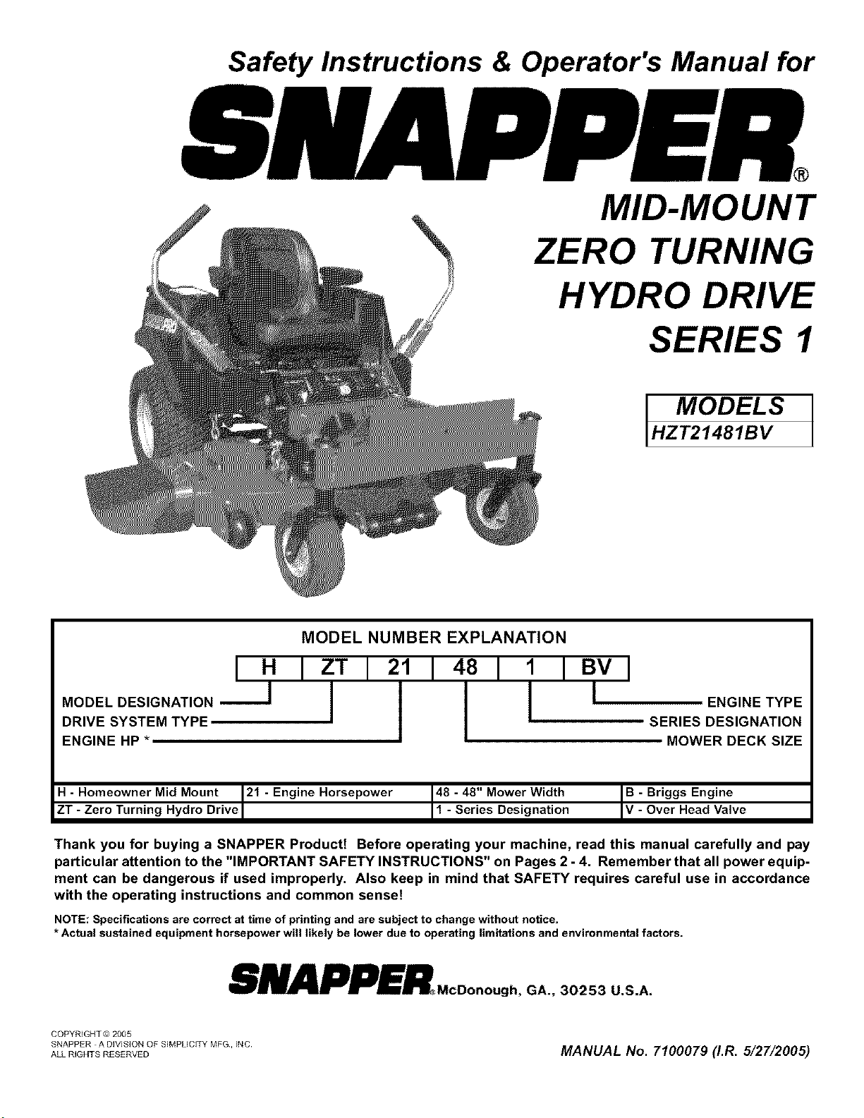
Safety Instructions & Operator's Manual for
MID-MOUNT
ZERO TURNING
HYDRO DRIVE
SERIES 1
MODELS
HZT21481BV
MODEL NUMBER EXPLANATION
I H I ZT I 21 I 481
MODEL DESIGNATION _
DRIVE SYSTEM TYPE
ENGINE HP *
1 IBVI
ENGINE TYPE
SERIES DESIGNATION
MOWER DECK SIZE
- Homeowner Mid Mount 21 - Engine Horsepower
ZT - Zero Turn ng Hydro Drve
48 - 48" Mower Width
1 - Series Designation B- Briggs Engine
Over Head Valve
Thank you for buying a SNAPPER Productt Before operating your machine, read this manual carefully and pay
particular attention to the "IMPORTANT SAFETY INSTRUCTIONS" on Pages 2 - 4. Remember that all power equip-
ment can be dangerous if used improperly. Also keep in mind that SAFETY requires careful use in accordance
with the operating instructions and common senset
NOTE: Specifications are correct at time of printing and are subject to change without notice.
* Actual sustained equipment horsepower will likely be lower due to operating limitations and environmental factors.
SNAPPER.ooooo°o.GA.,3o2s3U,A
COPYRIGHT © 2005
SNAPPER A DIVISION OF SIMPUCITY MFG, INC
ALLRIGHTSRESERVED MANUAL No. 7"100079 (LR. 5/27"/2005)

IMPORTANT SAFETY INSTRUCTIONS A
WARNING: This powerful cutting machine is capable of amputating hands and feet and can throw objects that can
cause injury and damage! Failure to comply with the following SAFETY instructions could result in serious injury
or death to the operator or other persons. The owner of the machine must understand these instructions and
must allow only persons who understand these instructions to operate machine. Each person operating the
machine must be of sound mind and body and must not be under the influence of any substance, which might
impair vision, dexterity or judgment. If you have any questions pertaining to your machine which your dealer can-
not answer to your satisfaction, call or write the Customer Service Department at SNAPPER Products Inc.,
McDonough, Georgia 30253. Phone: (1-800-935-2967).
PROTECTION FOR CHILDREN
Tragic accidents can occur if the operator is not alert
to the presence of children. Children are often attract-
ed to the machine and the mowing activity. Children
who have been given rides in the past may suddenly
appear in the mowing area for another ride and be run
over or backed over by the machine. Never assume
that children will remain where you last saw them.
1. KEEP children out of the mowing area and under the
watchful care of a responsible adult other than the opera-
tor.
2. DO NOT allow children in yard when machine is operated
(even with the blade OFF).
3. DO NOT allow children or others to ride on machine,
attachments or towed equipment (even with the blades
OFF). They may fall and be seriously injured.
4. DO NOT allow pre-teenage children to operate machine.
5. ALLOW only responsible adults & teenagers with mature
judgment under close adult supervision to operate
machine.
6. DO NOT operate blades in reverse. STOP BLADES. LOOK
and SEE behind and down for children, pets and hazards
before and while backing.
7. USE EXTRA CARE when approaching blind comers,
shrubs, trees, or other objects that may obscure vision.
PROTECTION AGAINST TIPOVERS
(Continued From Previous Column)
5. STAY ALERT for holes and other hidden hazards. Tall
grass can hide obstacles. Keep away from ditches,
washouts, culverts, fences and protruding objects.
6. KEEPA SAFE DISTANCE (at least 3 feet) away from edge
of ditches and other drop offs. The machine could turn
over if an edge caves in.
7. Always begin forward motion slowly and with caution.
8. Useweights or aweighted load carrier inaccordance with
instructions supplied with a grass catcher. DO NOT oper-
ate machine on slopes exceeding 10 degrees (18% grade)
when equipped with grass catcher.
9. DO NOT put your foot on the ground to try tostabilize the
machine.
10. DO NOT operate machine on wet grass. Reduced traction
could cause sliding.
11. Chose a low enough speed setting so that you will not
have tostop or shift on a slope. Tires may losetraction on
slopes even though the brakes are functioning properly.
12. DO NOT operate machine under anycondition where trac-
tion, steering or stability is doubtful.
13. Always keep the machine in gear when going down
slopes. DO NOT shift to neutral (or actuate hydro roll
release) and coast downhill.
PROTECTION AGAINST TIPOVERS
Slopes are a major factor related to loss-of-control and
tip-over accidents, which can result in severe injury or
death. All slopes require extra CAUTION. If you cannot
back up the slope or if you feel uneasy on the slope,
DO NOT mow it. Use extra care with grass catchers or
other attachments; these affect the handling and the
stability of the machine.
1. DO NOT operate machine on slopes exceeding 15
degrees (27% grade).
2. Exercise EXTREME CAUTION on slopes above 10
degrees (18% grade). Turn blades OFF when traveling
uphill. Usea slow speed and avoid sudden or sharp turns.
3. DO NOT operate machine back and forth across face of
slopes. Operate up and down. Practice on slopes with
blades off.
4. AVOIDstarting, stopping or turning on slopes. If machine
stops going uphill or tires lose traction, turn blades OFF
and back slowly straight down the slope.
PREPARATION
1. Read, understand, and follow instructions and warnings
in this manual and on the machine, engine and attach-
ments. Know the controls and the proper use of the
machine before starting.
2. Only mature, responsible persons shall operate the
machine and only after proper instruction.
3. Data indicates that operators age 60 and above, are
involved in a large percentage of mower-related injuries.
These operators should evaluate their ability to operate
the mower safely enough to protect themselves and oth-
ers from serious injury.
4. Handle fuel with extra care. Fuels are flammable and
vapors are explosive. Use only an approved fuel contain-
er. DO NOT remove fuel cap or add fuel with engine run-
ning. Add fuel outdoors only with engine stopped and
cool. Clean spilled fuel from machine. DO NOT smoke.
5. Practice operation of machinewith BLADES OFF to learn
controls and develop skills.
6. Check the area to be mowed and remove all objects such
as toys, wire, rocks, limbs and other objects that could
cause injury if thrown by blade or interfere with mowing.

TABLE OF CONTENTS
IMPORTANT SAFETY INSTRUCTIONS ..................................... 2-4
TABLE OF CONTENTS ................................................... 5
SECTION 1 - FAMILIARIZATION ............................................ 6
SECTION 2 -SAFETY MESSAGES AND SYMBOLS ........................... 7-8
SECTION 3 - OPERATING INSTRUCTIONS ................................ 9-13
Pre-start Checklist ................................................ 9-16
Starting & Stopping Engine, Blades & Parking Brake .................. 10-11
Starting & Stopping Mower Blades .................................... 11
Parking Brake ...................................................... 11
Cutting Height Adjustment ........................................... 12
Driving & Stopping Machine ....................................... 12-t3
Safety Interlock System Check ........................................ 13
SECTION 4- MAINTENANCE INSTRUCTIONS ............................ 14-t8
Change Engine Oil .................................................. t4
Check Mower Blade ................................................. t4
Check Mower Drive Belt ............................................. t5
Check Belt Tension ................................................. 15
Service - After every 25 Hours (Engine Components) ..................... 15
Service - After every 25 Hours (Mower Components) ..................... 15
Lubrication ..................................................... 15-t6
Mower Blade Spindle Lubrication ..................................... t5
Mower Deck Linkage Lubrication ...................................... t5
Front Wheel Bearings Lubrication ..................................... t6
Hydro Pump Lubrication ............................................. 16
Other Lubrication ................................................... 16
Before Operating Machine ........................................... 16
Annually - End of Season ......................................... 16-18
Engine Service ..................................................... 16
Fuel Filter Replacement ............................................. 17
Deck Removal ................................................... 17-18
Hydraulic Fluid Filters ............................................... 18
SECTION 5 - ADJUSTMENTS AND REPAIR ............................... t9-27
Neutral Position Adjustments ...................................... t9-20
Mower Deck Adjustment (Levelness) ................................ 20-21
Parking Brake Adjustment ........................................... 21
Traction Belt Tension & Replacement .................................. 22
Blade Brake/Electric Clutch Adjustment ................................ 22
Tracking Adjustment .............................................. 22-23
Mower Drive Belt Removal, Replacement & Adjustment ................... 23
Engine Adjustments & Repair ......................................... 24
Mower Blade Replacement ........................................... 24
Mower Blade Sharpening ............................................ 24
Battery Removal .................................................... 25
Battery Installation .................................................. 25
Battery Charging ................................................... 25
Battery Testing ..................................................... 26
New Battery Preparation ............................................. 26
Hydraulic System, Purging ........................................... 27
TROUBLESHOOTING ................................................. 28-29
SERVICE SCHEDULE ................................................... 30
Maintenance/Replacement Parts ...................................... 30
WARRANTY ........................................................... 31
PRIMARY MAINTENANCE ............................................. 32-35
PRODUCT REGISTRATION FORM ......................................... 36
IMPORTANT
NOTICE: Operator Protective Structures are available as optional kits for the Mid-Mount and Out-Front Z-Rider
machines. These structures, when installed and used properly can offer additional security to the operator
against serious injury in the event of a tip over accident. Operator Protective Structures may be required by local
ordinances. Discuss your mowing application and ordinances with your local Snapper Dealer.
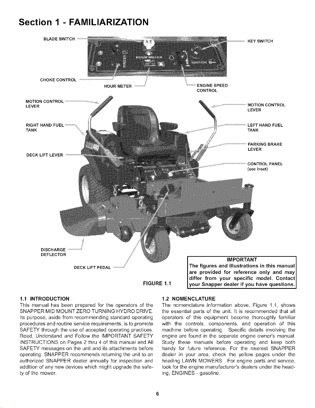
Section 1 - FAMILIARIZATION
BLADE SWITCH
KEY SWITCH
CHOKE CONTROL
HOUR METER _
MOTION CONTROL
LEVER
ENGINE SPEED
CONTROL
_ MOTION CONTROL
LEVER
RIGHT HAND FUEL
TANK .....
DECK LIFT LEVER
LEFT HAND FUEL
TANK
PARKING BRAKE
LEVER
CONTROL PANEL
(see inset)
DISCHARGE
DEFLECTOR
9
DECK LIFT PEDAL /
FIGURE 1.1
1.1 INTRODUCTION
This manual has been prepared for the operators of the
SNAPPER MID MOUNT ZERO TURNING HYDRO DRIVE.
Its purpose, aside from recommending standard operating
procedures and routine service requirements, is to promote
SAFETY through the use of accepted operating practices.
Read, Understand and Follow the IMPORTANT SAFETY
INSTRUCTIONS on Pages 2 thru 4 of this manual and All
SAFETY messages on the unit and its attachments before
operating, SNAPPER recommends returning the unit to an
authorized SNAPPER dealer annually for inspection and
addition of any new devices which might upgrade the safe-
ty of the mower.
IMPORTANT
The figures and illustrations in this manual
are provided for reference only and may I
differ from your specific model. Contact
your Snapper dea er f you have quest ons.
1.2 NOMENCLATURE
The nomenclature information above, Figure 1,1, shows
the essential parts of the unit, It is recommended that all
operators of this equipment become thoroughly familiar
with the controls, components, and operation of this
machine before operating, Specific details involving the
engine are found in the separate engine owner's manual.
Study these manuals before operating and keep both
handy for future reference, For the nearest SNAPPER
dealer in your area, check the yellow pages under the
heading LAWN MOWERS. For engine parts and service,
look for the engine manufacturer's dealers under the head-
ing, ENGINES - gasoline.
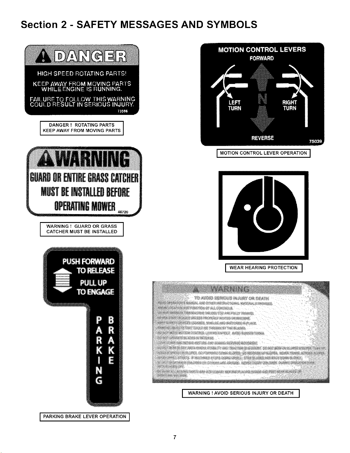
Section 2 - SAFETY MESSAGES AND SYMBOLS
KEDp_N_R"oO_'N_N_P_sTs
GWBORENTIREGRASSCATCfl_
MUSTBEIHSTAL_DB_ORE
I_1tllI r l
WARNING ! GUARD OR GRASS
CATCHER MUST BE INSTALLED
I MOTION CONTROL LEVER OPERATION I
I WEAR HEARING PROTECTION I
WARNING ! AVOID SERIOUS INJURY OR DEATH ]
.I
I PARKING BRAKE LEVER OPERATION I
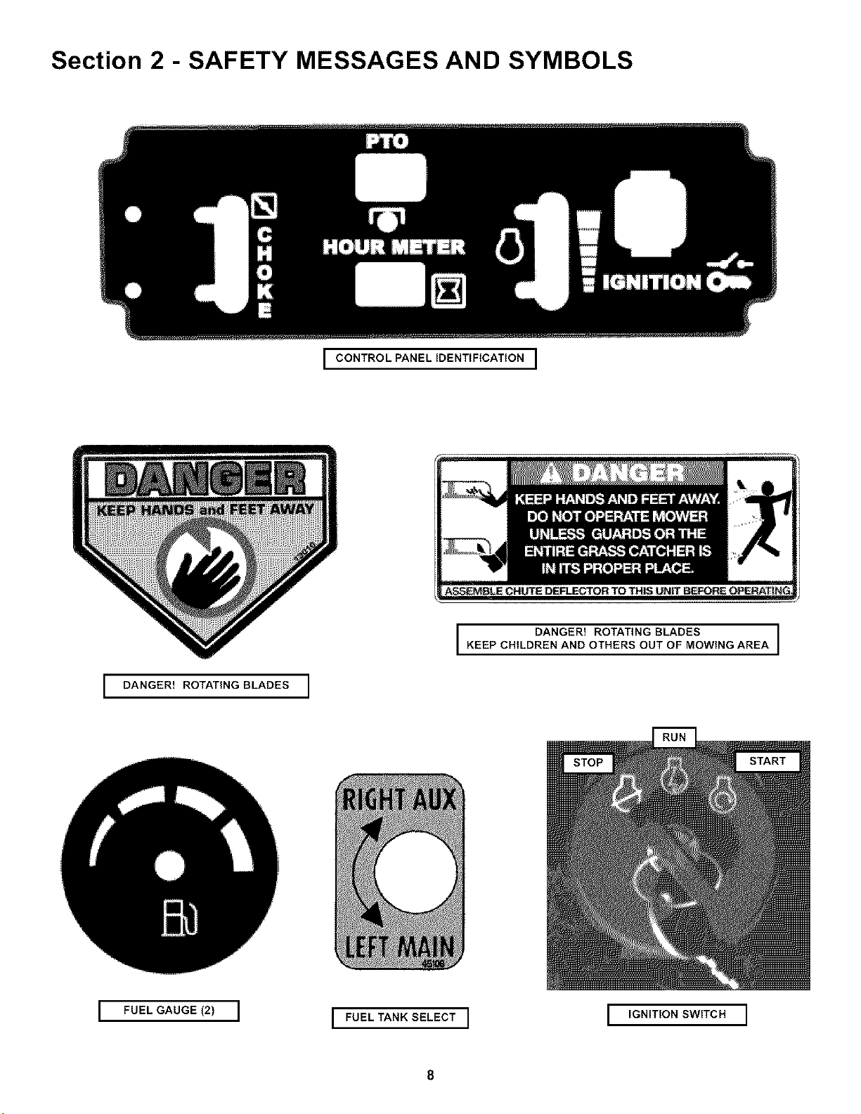
Section 2 - SAFETY MESSAGES AND SYMBOLS
I CONTROL PANEL IDENTIFICATION I
I DANGER! ROTATING BLADES I
I DANGER! ROTATING BLADES I
KEEP CHILDREN AND OTHERS OUT OF MOWING AREA
I FUEL GAUGE (2) I
I FUEL TANK SELECT I
I IGNITION SWITCH I
Section 3 - OPERATING INSTRUCTIONS
3.1 PRE-START CHECK LIST
Make the following checks and perform the service
required before each start-up.
3.1.1. Check tires and add or release air as needed to
bring pressure to 12 psi in drive tires. Pressure in front
caster wheels should be 25 psi.
3.1.2. Check guards, deflectors and covers to make
sure all are in place and securely tightened,
3.1.3. Check engine oil and add oil as needed to bring
level up to the FULL mark. Refer to engine owner's
manual for oil specifications. See Figure 3.1.
FIGURE 3.1
3.1.4. Check Blade Switch to insure it works freely.
See Figure 3.2.
1. Pull the Blade Switch up to the "ON" position to
engage or turn "ON" the mower blades.
2. Push Blade Switch down to the "OFF" position to
disengage (or turn "OFF") the blades.
FIGURE 3.2
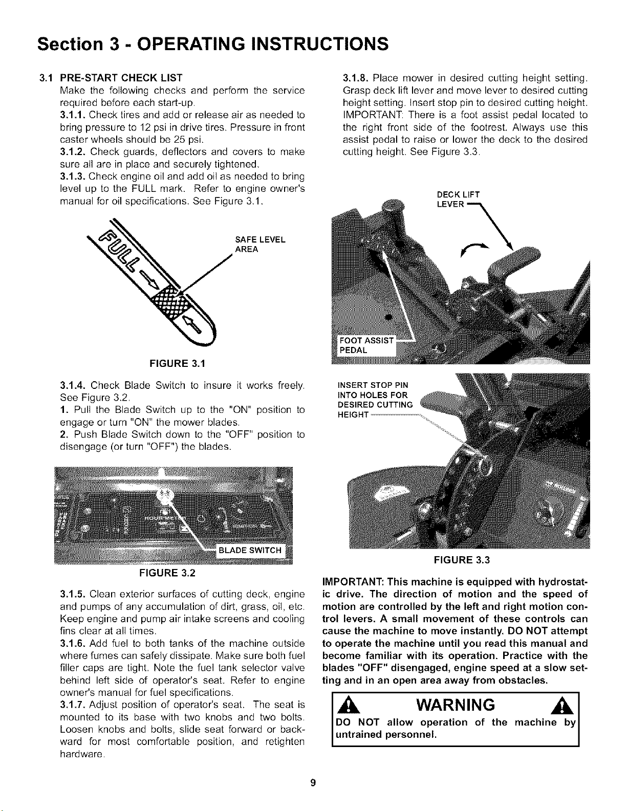
3.1.8. Place mower in desired cutting height setting,
Grasp deck lift lever and move lever to desired cutting
height setting. Insert stop pin to desired cutting height,
IMPORTANT: There is a foot assist pedal located to
the right front side of the footrest. Always use this
assist pedal to raise or lower the deck to the desired
cutting height. See Figure 3.3.
DECK LIFT
INSERT STOP PIN
INTO HOLES FOR
DESIRED CUTTING
3.1.5. Clean exterior surfaces of cutting deck, engine
and pumps of any accumulation of dirt, grass, oil, etc.
Keep engine and pump air intake screens and cooling
fins clear at all times.
3.1.6. Add fuel to both tanks of the machine outside
where fumes can safely dissipate. Make sure both fuel
filler caps are tight, Note the fuel tank selector valve
behind left side of operator's seat, Refer to engine
owner's manual for fuel specifications.
3.1.7. Adjust position of operator's seat. The seat is
mounted to its base with two knobs and two bolts.
Loosen knobs and bolts, slide seat forward or back-
ward for most comfortable position, and retighten
hardware.
FIGURE 3.3
IMPORTANT: This machine is equipped with hydrostat-
ic drive. The direction of motion and the speed of
motion are controlled by the left and right motion con-
trol levers. A small movement of these controls can
cause the machine to move instantly. DO NOT attempt
to operate the machine until you read this manual and
become familiar with its operation. Practice with the
blades "OFF" disengaged, engine speed at a slow set-
ting and in an open area away from obstacles.
WARNING A
DO NOT allow operation of the machine by
untrained personnel.
Section 3 - OPERATING INSTRUCTIONS
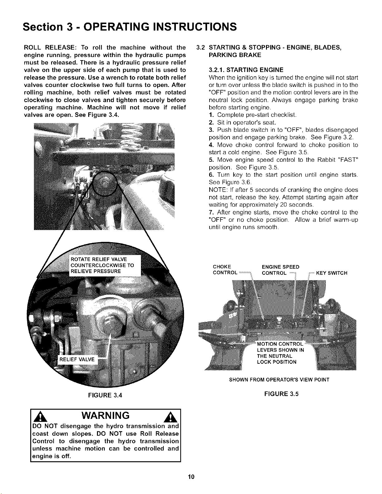
ROLL RELEASE: To roll the machine without the
engine running, pressure within the hydraulic pumps
must be released. There is a hydraulic pressure relief
valve on the upper side of each pump that is used to
release the pressure. Use a wrench to rotate both relief
valves counter clockwise two full turns to open. After
rolling machine, both relief valves must be rotated
clockwise to close valves and tighten securely before
operating machine. Machine will not move if relief
valves are open. See Figure 3.4.
3.2 STARTING & STOPPING - ENGINE, BLADES,
PARKING BRAKE
3.2.1. STARTING ENGINE
When the ignition key is turned the engine will not start
or turn over unless the blade switch is pushed in to the
"OFF" position and the motion control levers are in the
neutral lock position. Always engage parking brake
before starting engine.
1. Complete pre-start checklist.
2. Sit in operator's seat.
3. Push blade switch in to "OFF", blades disengaged
position and engage parking brake. See Figure 3.2.
4. Move choke control forward to choke position to
start a cold engine. See Figure 3.5.
5. Move engine speed control to the Rabbit "FAST"
position. See Figure 3.5.
6. Turn key to the start position until engine starts.
See Figure 3.6.
NOTE: If after 5 seconds of cranking the engine does
not start, release the key. Attempt starting again after
waiting for approximately 20 seconds.
7. After engine starts, move the choke control to the
"OFF" or no choke position. Allow a brief warm-up
until engine runs smooth.
CHOKE ENGINE SPEED
CONTROL .....................CONTROL KEY SWITCH
MOTION CONTROL
LEVERS SHOWN IN
THE NEUTRAL
LOCK POSITION
FIGURE 3.4
SHOWN FROM OPERATOR'S VIEW POINT
FIGURE 3.5
WARNING
NOT disengage the hydro transmission and
coast down slopes. DO NOT use Roll Release
Control to disengage the hydro transmission
unless machine motion can be controlled and
engine is off.
10
Section 3 - OPERATING INSTRUCTIONS
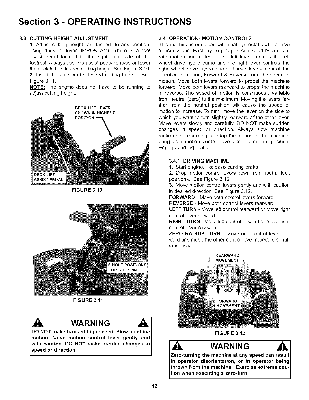
3.3 CUTTING HEIGHT ADJUSTMENT
1. Adjust cutting heighL as desired, to any position,
using deck lift lever. IMPORTANT: There is a foot
assist pedal located to the right front side of the
footrest, Always use this assist pedal to raise or lower
the deck to the desired cutting height. See Figure 3.10,
2. Insert the stop pin to desired cutting height. See
Figure 3.11.
NOTE: The engine does not have to be running to
adjust cutting height.
DECK LIFT LEVER
SHOWN tN HIGHEST
FIGURE 3.10
FIGURE 3.11
6 HOLE POSITIONS
FOR STOP PIN
WARNING
DO NOT make turns at high speed. Slow machine
motion. Move motion control lever gently and
with caution. DO NOT make sudden changes in
speed or direction.
3.4 OPERATION- MOTION CONTROLS
This machine is equipped with dual hydrostatic wheel drive
transmissions. Each hydro pump is controlled by a sepa-
rate motion control lever. The left lever controls the left
wheel drive hydro pump and the right lever controls the
right wheel drive hydro pump. These levers control the
direction of motion, Forward & Reverse, and the speed of
motion, Move both levers forward to propel the machine
forward, Move both levers rearward to propel the machine
in reverse. The speed of motion is continuously variable
from neutral (zero) to the maximum, Moving the levers far-
ther from the neutral position will cause the speed of
motion to increase. To turn, move the lever on the side to
which you want to turn slightly rearward of the other lever,
Move levers slowly and carefully. DO NOT make sudden
changes in speed or direction, Always slow machine
motion before turning, To stop the motion of the machine,
bring both motion control levers to the neutral position.
Engage parking brake.
3.4.1. DRIVING MACHINE
1. Start engine, Release parking brake.
2. Drop motion control levers down from neutral lock
positions. See Figure 3.12.
3. Move motion control levers gently and with caution
in desired direction, See Figure 3,12.
FORWARD - Move both control levers forward.
REVERSE - Move both control levers rearward.
LEFT TURN - Move left control rearward or move right
control lever forward,
RIGHT TURN - Move left control forward or move right
control lever rearward.
ZERO RADIUS TURN - Move one control lever for-
ward and move the other control lever rearward simul-
taneously.
REARWARD
MC
FORWARD
MOVEMENT
FIGURE 3.12
WARNING
Zero-turning the machine at any speed can result
in operator disorientation, or in operator being
thrown from the machine. Exercise extreme cau-
tion when executing a zero-turn.
12
Section 3 - OPERATING INSTRUCTIONS
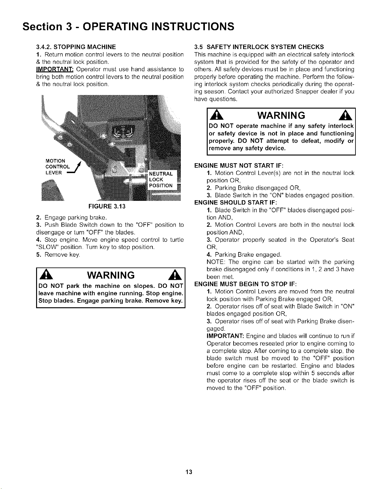
3.4.2. STOPPING MACHINE
1. Return motion control levers to the neutral position
& the neutral lock position,
IMPORTANT: Operator must use hand assistance to
bring both motion control levers to the neutral position
& the neutral lock position.
MOTION
CONTROL
LEVER
POSITION
FIGURE 3.13
2. Engage parking brake.
3. Push Blade Switch down to the "OFF" position to
disengage or turn "OFF" the blades.
4. Stop engine. Move engine speed control to turtle
"SLOW" position. Turn key to stop position.
5. Remove key.
WARNING ,A,
DO NOT park the machine on slopes. DO NOT I
leave machine with engine running. Stop engine.
Stop b ades. Engage park ng brake. Remove key.
3.5 SAFETY INTERLOCK SYSTEM CHECKS
This machine is equipped with an electrical safety interlock
system that is provided for the safety of the operator and
others, All safety devices must be in place and functioning
properly before operating the machine, Perform the follow-
ing interlock system checks periodically during the operat-
ing season. Contact your authorized Snapper dealer if you
have questions.
WARNING
DO NOT operate machine if any safety interlock
or safety device is not in place and functioning
properly. DO NOT attempt to defeat, modify or
remove any safety device.
ENGINE MUST NOT START IF:
1. Motion Control Lever(s) are not in the neutral lock
position OR,
2. Parking Brake disengaged OR,
3. Blade Switch in the "ON" blades engaged position.
ENGINE SHOULD START IF:
1. Blade Switch in the "OFF" blades disengaged posi-
tion AND,
2. Motion Control Levers are both in the neutral lock
position AND,
3. Operator properly seated in the Operator's Seat
OR,
4. Parking Brake engaged,
NOTE: The engine can be started with the parking
brake disengaged only if conditions in 1,2 and 3 have
been met.
ENGINE MUST BEGIN TO STOP IF:
1. Motion Control Levers are moved from the neutral
lock position with Parking Brake engaged OR,
2. Operator rises off of seat with Blade Switch in "ON"
blades engaged position OR,
3. Operator rises off of seat with Parking Brake disen-
gaged.
IMPORTANT: Engine and blades will continue to run if
Operator becomes reseated prior to engine coming to
a complete stop. After coming to a complete stop, the
blade switch must be moved to the "OFF" position
before engine can be restarted, Engine and blades
must come to a complete stop within 5 seconds after
the operator rises off the seat or the blade switch is
moved to the "OFF" position.
13
Section 4 - MAINTENANCE
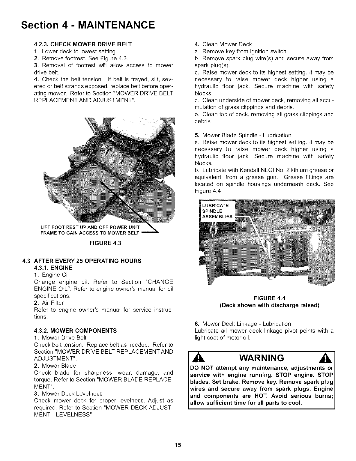
4.2.3. CHECK MOWER DRIVE BELT
1. Lower deck to lowest setting,
2. Remove footrest, See Figure 4.3.
3. Removal of footrest will allow access to mower
drive belt.
4. Check the belt tension, if belt is frayed, slit, sev-
ered or belt strands exposed, replace belt before oper-
ating mower. Refer to Section "MOWER DRIVE BELT
REPLACEMENT AND ADJUSTMENT",
4. Clean Mower Deck
a. Remove key from ignition switch.
b. Remove spark plug wire(s) and secure away from
spark plug(s).
c. Raise mower deck to its highest setting. It may be
necessary to raise mower deck higher using a
hydraulic floor jack. Secure machine with safety
blocks.
d. Clean underside of mower deck, removing all accu-
mulation of grass clippings and debris.
e. Clean top of deck, removing all grass clippings and
debris.
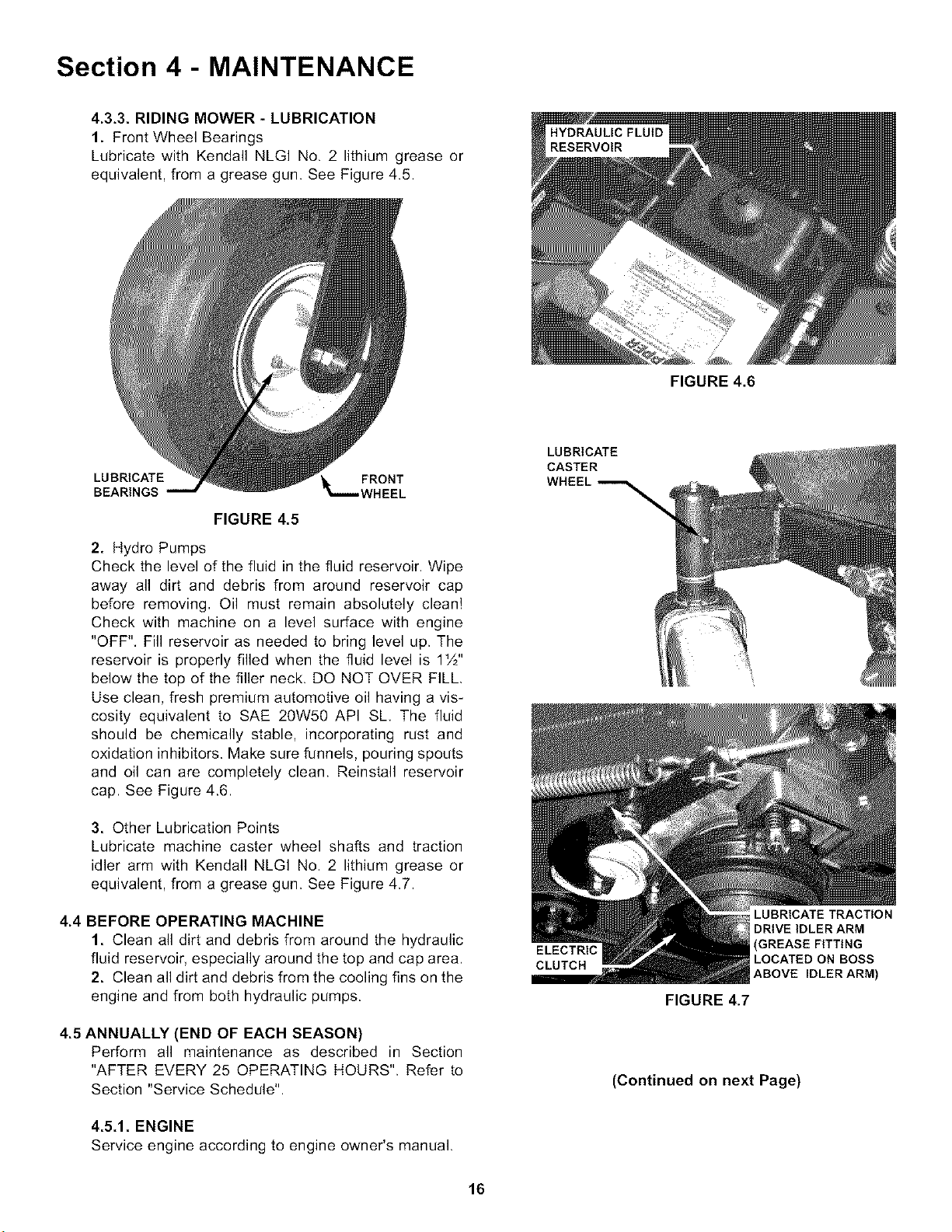
5. Mower Blade Spindle - Lubrication
a. Raise mower deck to its highest setting. It may be
necessary to raise mower deck higher using a
hydraulic floor jack. Secure machine with safety
blocks.
b. Lubricate with Kendall NLGI No. 2 lithium grease or
equivalent, from a grease gun. Grease fittings are
located on spindle housings underneath deck. See
Figure 4.4.
LIFT FOOT REST UP AND OFF POWER UNIT
FRAME TO GAIN ACCESS TO MOWER BELT
FIGURE 4.3
4.3 AFTER EVERY 25 OPERATING HOURS
4.3.1. ENGINE
1. Engine Oil
Change engine oil. Refer to Section "CHANGE
ENGINE OIL". Refer to engine owner's manual for oil
specifications.
2. Air Filter
Refer to engine owner's manual for service instruc-
tions.
4.3.2. MOWER COMPONENTS
1. Mower Drive Belt
Check belt tension. Replace belt as needed. Refer to
Section "MOWER DRIVE BELT REPLACEMENTAND
ADJUSTMENT",
2. Mower Blade
Check blade for sharpness, wear, damage, and
torque. Refer to Section "MOWER BLADE REPLACE-
MENT".
3. Mower Deck Levelness
Check mower deck for proper levelness. Adjust as
required. Refer to Section "MOWER DECK ADJUST-
MENT - LEVELNESS".
FIGURE 4.4
(Deck shown with discharge raised)
6. Mower Deck Linkage - Lubrication
Lubricate all mower deck linkage pivot points with a
light coat of motor oil.
WARNING
DO NOT attempt any maintenance, adjustments or
service with engine running. STOP engine. STOP
blades. Set brake. Remove key. Remove spark plug
wires and secure away from spark plugs. Engine
and components are HOT. Avoid serious burns
allow sufficient time for all parts to cool.
15
Section 4 - MAINTENANCE
4.3.3. RIDING MOWER - LUBRICATION
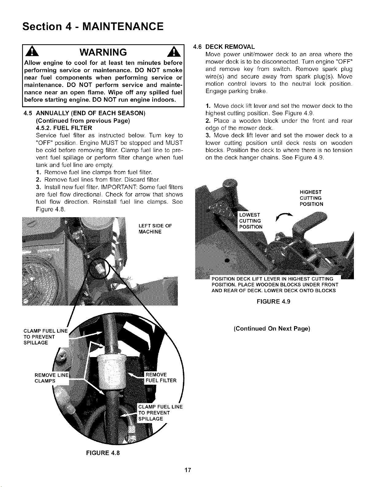
1. Front Wheel Bearings
Lubricate with Kendall NLGI No. 2 lithium grease or
equivalent, from a grease gun. See Figure 4.5.
FIGURE 4.6
LUBRICATE _.... FRONT
BEARINGS WHEEL
FIGURE 4.5
2. Hydro Pumps
Check the level of the fluid in the fluid reservoir. Wipe
away all dirt and debris from around reservoir cap
before removing, Oil must remain absolutely clean!
Check with machine on a level surface with engine
"OFF", Fill reservoir as needed to bring level up. The
reservoir is properly filled when the fluid level is 11/2''
below the top of the filler neck. DO NOT OVER FILL,
Use clean, fresh premium automotive oil having a vis-
cosity equivalent to SAE 20W50 API SL, The fluid
should be chemically stable, incorporating rust and
oxidation inhibitors. Make sure funnels, pouring spouts
and oil can are completely clean. Reinstall reservoir
cap. See Figure 4.6.
3. Other Lubrication Points
Lubricate machine caster wheel shafts and traction
idler arm with Kendall NLGI No. 2 lithium grease or
equivalent, from a grease gun. See Figure 4.7.
4.4 BEFORE OPERATING MACHINE
1. Clean all dirt and debris from around the hydraulic
fluid reservoir, especially around the top and cap area.
2. Clean all dirt and debris from the cooling fins on the
engine and from both hydraulic pumps.
4.5 ANNUALLY (END OF EACH SEASON)
Perform all maintenance as described in Section
"AFTER EVERY 25 OPERATING HOURS". Refer to
Section "Service Schedule".
4.5.1. ENGINE
Service engine according to engine owner's manual.
LUBRICATE
CASTER
WHEEL_
ELECTRIC
CLUTCH
FIGURE 4.7
LUBRICATE TRACTION
DRIVE IDLER ARM
(GREASE FITTING
LOCATED ON BOSS
ABOVE IDLER ARM)
(Continued on next Page)
16
Section 4 - MAINTENANCE
WARNING
Allow engine to cool for at least ten minutes before
performing service or maintenance. DO NOT smoke
near fuel components when performing service or
maintenance. DO NOT perform service and mainte-
nance near an open flame. Wipe off any spilled fuel
before starting engine. DO NOT run engine indoors.
4.5 ANNUALLY (END OF EACH SEASON)
(Continued from previous Page)
4.5.2. FUEL FILTER
Service fuel filter as instructed below. Turn key to
"OFF" position. Engine MUST be stopped and MUST
be cold before removing filter. Clamp fuel line to pre-
vent fuel spillage or perform filter change when fuel
tank and fuel line are empty.
1. Remove fuel line clamps from fuel filter,
2. Remove fuel lines from filter. Discard filter.
3. Install new fuel filter. IMPORTANT: Some fuel filters
are fuel flow directional. Check for arrow that shows
fuel flow direction. Reinstall fuel line clamps. See
Figure 4.8.
LEFT SIDE OF
MACHINE
CLAMP FUEL LINE
TO PREVENT
SPILLAGE
REMOVE LINE
CLAMPS
CLAMP FUEL LINE
TO PREVENT
SPILLAGE
4.6 DECK REMOVAL
Move power unit/mower deck to an area where the
mower deck is to be disconnected. Turn engine "OFF"
and remove key from switch, Remove spark plug
wire(s) and secure away from spark plug(s), Move
motion control levers to the neutral lock position.
Engage parking brake.
1. Move deck lift lever and set the mower deck to the
highest cutting position, See Figure 4.9.
2. Place a wooden block under the front and rear
edge of the mower deck.
3. Move deck lift lever and set the mower deck to a
lower cutting position until deck rests on wooden
blocks. Position the deck to where there is no tension
on the deck hanger chains. See Figure 4.9.
HIGHEST
CUTTING
POSITION
CUTTING
POSITION
POSITION DECK LIFT LEVER IN HIGHEST CUTTING
POSITION. PLACE WOODEN BLOCKS UNDER FRONT
AND REAR OF DECK. LOWER DECK ONTO BLOCKS
FIGURE 4.9
(Continued On Next Page)
FIGURE 4.8
17
Section 5 -ADJUSTMENTS & REPAIR
WARNING
Exercise EXTREME CAUTION when making this
adjustment, due to c ose prox m ty of mov ng parts.
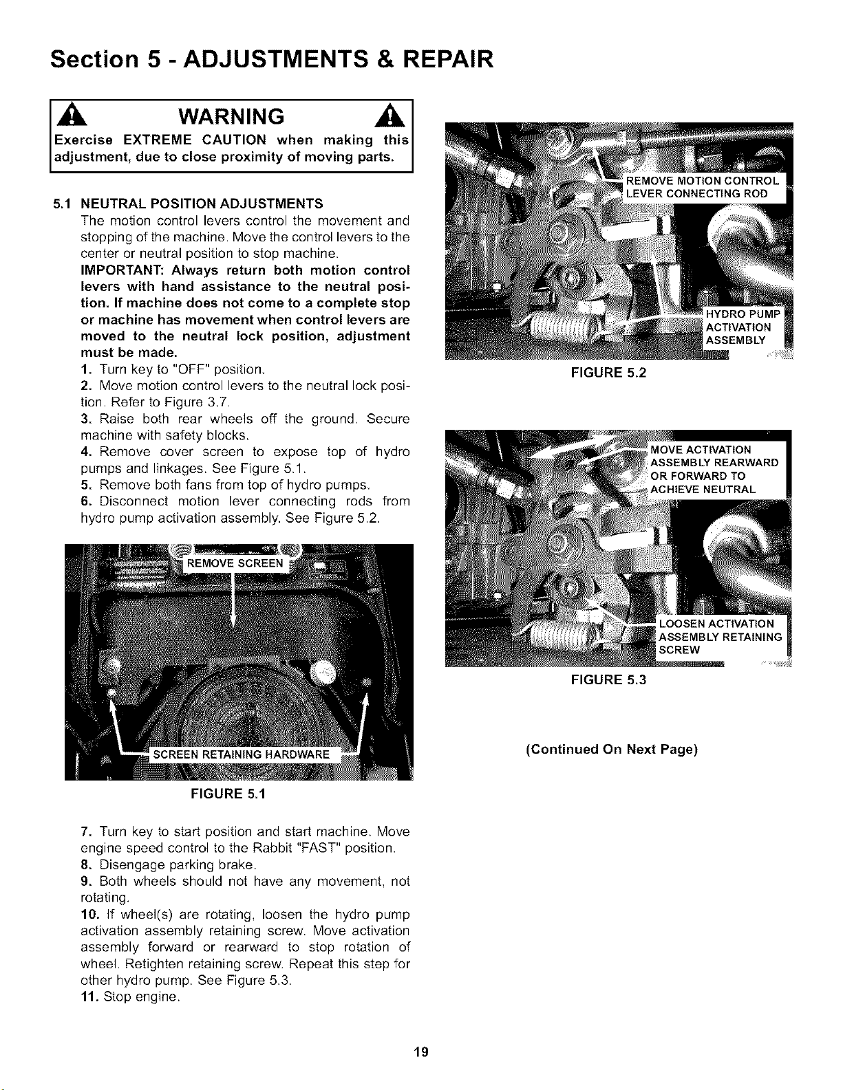
5.1 NEUTRAL POSITION ADJUSTMENTS
The motion control levers control the movement and
stopping of the machine. Move the control levers to the
center or neutral position to stop machine.
IMPORTANT: Always return both motion control
levers with hand assistance to the neutral posi-
tion. If machine does not come to a complete stop
or machine has movement when control levers are
moved to the neutral lock position, adjustment
must be made.
1. Turn key to "OFF" position,
2. Move motion control levers to the neutral lock posi-
tion. Refer to Figure 3.7.
3. Raise both rear wheels off the ground. Secure
machine with safety blocks.
4. Remove cover screen to expose top of hydro
pumps and linkages. See Figure 5.1.
5. Remove both fans from top of hydro pumps,
6. Disconnect motion lever connecting rods from
hydro pump activation assembly. See Figure 5.2.
FIGURE 5.1
FIGURE 5.2
FIGURE 5.3
(Continued On Next Page)
7. Turn key to start position and start machine. Move
engine speed control to the Rabbit "FAST" position.
8. Disengage parking brake.
9. Both wheels should not have any movement, not
rotating.
10. If wheel(s) are rotating, loosen the hydro pump
activation assembly retaining screw. Move activation
assembly forward or rearward to stop rotation of
wheel. Retighten retaining screw. Repeat this step for
other hydro pump. See Figure 5.3.
11. Stop engine.
19
Section 5 -ADJUSTMENTS & REPAIR
5.1 NEUTRAL POSITION ADJUSTMENTS
(Continued From Previous Page)
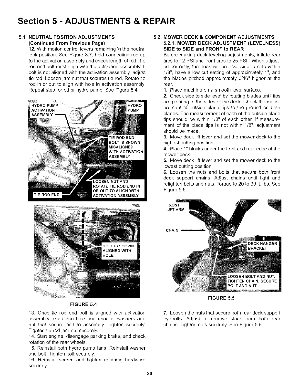
12. With motion control levers remaining in the neutral
lock position, See Figure 3.7, hold connecting rod up
to the activation assembly and check length of rod, Tie
rod end bolt must align with the activation assembly. If
bolt is not aligned with the activation assembly, adjust
tie rod. Loosen jam nut that secures tie rod, Rotate tie
rod in or out to align with hole in activation assembly.
Repeat step for other hydro pump. See Figure 5.4.
5.2 MOWER DECK & COMPONENT ADJUSTMENTS
5.2.1. MOWER DECK ADJUSTMENT (LEVELNESS)
SIDE to SIDE and FRONT to REAR
Before making deck leveling adjustments, inflate rear
tires to 12 PSI and front tires to 25 PSh When adjust-
ed correctly, the deck will be level side to side within
1/8", have a low cut setting of approximately 1", and
the blades pitched approximately 3/16" higher at the
rear.
1. Place machine on a smooth level surface,
2. Check side to side level by rotating blades until tips
are pointing to the sides of the deck. Check the meas-
urement of outside blade tips to the ground on both
blades. The measurement of each of the outside blade
tips should be within 1/8" of each other. If measure-
ment of the blade tips is not within 1/8", adjustment
should be made.
3. Move deck lift lever and set the mower deck to the
highest cutting position,
4. Place 1" blocks under the front and rear edge of the
mower deck.
5. Move deck lift lever and set the mower deck to the
lowest cutting position,
6. Loosen the nuts and bolts that secure both front
deck support chains, Adjust chains until tight and
retighten bolts and nuts. Torque to 20 to 30 ft. Ibs. See
Figure 5.5.
FRONT
LIFT ARM
CHAIN
FIGURE 5.4
13. Once tie rod end bolt is aligned with activation
assembly insert into hole and reinstall washers and
nut that secure bolt to assembly. Tighten securely.
Tighten tie rod jam nut securely.
14. Start engine, disengage parking brake, and check
rotation of the rear wheels.
15. Reinstall both hydro pump fans. Reinstall washer
and bolt. Tighten bolt securely.
16. Reinstall screen and tighten retaining hardware
securely.
2O
FIGURE 5.5
7. Loosen the nuts that secure both rear deck support
eyebolts. Adjust to remove slack from both rear
chains. Tighten nuts securely. See Figure 5.6.
Section 5 -ADJUSTMENTS & REPAIR
WARNING
DO NOT attempt any maintenance, adjustments or
service with engine running. STOP engine. STOP
blades. Set brake. Remove key. Remove spark plug
wires and secure away from spark plugs. Engine and
components are HOT. Avoid serious burns; allow suf-
ficient time for all parts to cool.
5.3 TRACTION BELT TENSION
The traction drive belt tension does not require adjustment.
If the belt is slipping, it will have to be replaced.
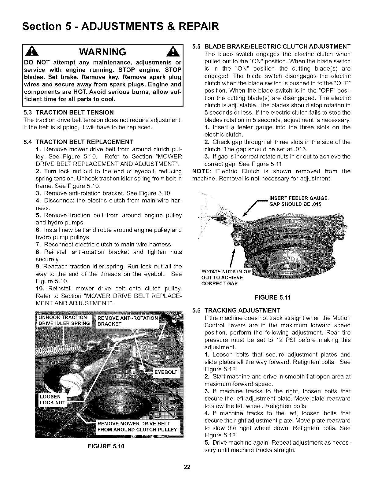
5.4 TRACTION BELT REPLACEMENT
1. Remove mower drive belt from around clutch pul-
ley. See Figure 5.10. Refer to Section "MOWER
DRIVE BELT REPLACEMENT AND ADJUSTMENT",
2. Turn lock nut out to the end of eyebolt, reducing
spring tension, Unhook traction idler spring from bolt in
frame. See Figure 5.10.
3. Remove anti-rotation bracket, See Figure 5.10,
4. Disconnect the electric clutch from main wire har-
ness.
5. Remove traction belt from around engine pulley
and hydro pumps.
6. Install new belt and route around engine pulley and
hydro pump pulleys.
7. Reconnect electric clutch to main wire harness.
8. Reinstall anti-rotation bracket and tighten nuts
securely.
9. Reattach traction idler spring, Run lock nut all the
way to the end of the threads on the eyebolt. See
Figure 5.10.
10. Reinstall mower drive belt onto clutch pulley.
Refer to Section "MOWER DRIVE BELT REPLACE-
MENT AND ADJUSTMENT".
UNHOOK TRACTION
FIGURE 5.10
5.5 BLADE BRAKE/ELECTRIC CLUTCH ADJUSTMENT
The blade switch engages the electric clutch when
pulled out to the "ON" position. When the blade switch
is in the "ON" position the cutting blade(s) are
engaged, The blade switch disengages the electric
clutch when the blade switch is pushed in to the "OFF"
position, When the blade switch is in the "OFF" posi-
tion the cutting blade(s) are disengaged. The electric
clutch is adjustable. The blades should stop rotation in
5 seconds or less. If the electric clutch fails to stop the
blades rotation in 5 seconds, adjustment is necessary.
1. Insert a feeler gauge into the three slots on the
electric clutch,
2. Check gap through all three slots in the side of the
clutch. The gap should be set at .015.
3. If gap is incorrect rotate nuts in or out to achieve the
correct gap, See Figure 5.11.
NOTE: Electric Clutch is shown removed from the
machine. Removal is not necessary for adjustment,
i ¸
INSERT FEELER GAUGE.
GAP SHOULD BE .015
5.6
/
ROTATE NUTS IN OR
OUT TO ACHIEVE
CORRECT GAP
FIGURE 5.11
TRACKING ADJUSTMENT
If the machine does not track straight when the Motion
Control Levers are in the maximum forward speed
position, perform the following adjustment. Rear tire
pressure must be set to 12 PSI before making this
adjustment,
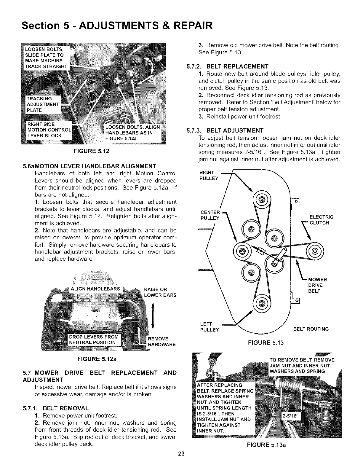
1. Loosen bolts that secure adjustment plates and
slide plates all the way forward. Retighten bolts. See
Figure 5.12.
2. Start machine and drive in smooth flat open area at
maximum forward speed.
3. If machine tracks to the right, loosen bolts that
secure the left adjustment plate, Move plate rearward
to slow the left wheel. Retighten bolts.
4. If machine tracks to the left, loosen bolts that
secure the right adjustment plate. Move plate rearward
to slow the right wheel down. Retighten bolts. See
Figure 5.12.
5. Drive machine again, Repeat adjustment as neces-
sary until machine tracks straight,
22
Section 5 -ADJUSTMENTS & REPAIR
FIGURE 5.12
5.6aMOTION LEVER HANDLEBAR ALIGNMENT
Handlebars of both left and right Motion Control
Levers should be aligned when levers are dropped
from their neutral lock positions. See Figure 5.12a. If
bars are not aligned:
1. Loosen bolts that secure handlebar adjustment
brackets to lever blocks, and adjust handlebars until
aligned. See Figure 5.12. Retighten bolts after align-
ment is achieved,
2. Note that handlebars are adjustable, and can be
raised or lowered to provide optimum operator com-
fort. Simply remove hardware securing handlebars to
handlebar adjustment brackets, raise or lower bars,
and replace hardware.
ALIGN HANDLEBARS
RAISE OR
LOWER BARS
I
HARDWARE
FIGURE 5.12a
5.7 MOWER DRIVE BELT REPLACEMENT AND
ADJUSTMENT
Inspect mower drive belt, Replace belt if it shows signs
of excessive wear, damage and/or is broken.
5.7.1. BELT REMOVAL
1. Remove power unit footrest.
2. Remove jam nut, inner nut, washers and spring
from front threads of deck idler tensioning rod. See
Figure 5,13a, Slip rod out of deck bracket, and swivel
deck idler pulley back.
23
3. Remove old mower drive belt. Note the belt routing.
See Figure 5.13.
5.7.2. BELT REPLACEMENT
1. Route new belt around blade pulleys, idler pulley,
and clutch pulley in the same position as old belt was
removed. See Figure 5.13.
2. Reconnect deck idler tensioning rod as previously
removed, Refer to Section 'Belt Adjustment' below for
proper belt tension adjustment.
3. Reinstall power unit footrest.
5.7.3. BELT ADJUSTMENT
To adjust belt tension, loosen jam nut on deck idler
tensioning rod, then adjust inner nut in or out until idler
spring measures 2-5/16" See Figure 513a Tighten
jam nut against inner nut after adjustment is achieved.
RIGHT
PULLEY
CENTER
PULLEY
ELECTRIC
CLUTCH
DRIVE
BELT
LEFT
PULLEY
BELT ROUTING
FIGURE 5.13
TO REMOVE BELT, REMOVE
JAM NUTAND INNER NUT,
WASHERS AND SPRING
FIGURE 5.13a
Section 5 -ADJUSTMENTS & REPAIR
WARNING
DO NOT attempt any maintenance, adjustments or
service with engine running. STOP engine. STOP
blades. Set brake. Remove key. Remove spark plug
wires and secure away from spark plugs. Engine and
components are HOT. Avoid serious burns; allow suf-
ficient time for all parts to cool.
5.10BATTERY
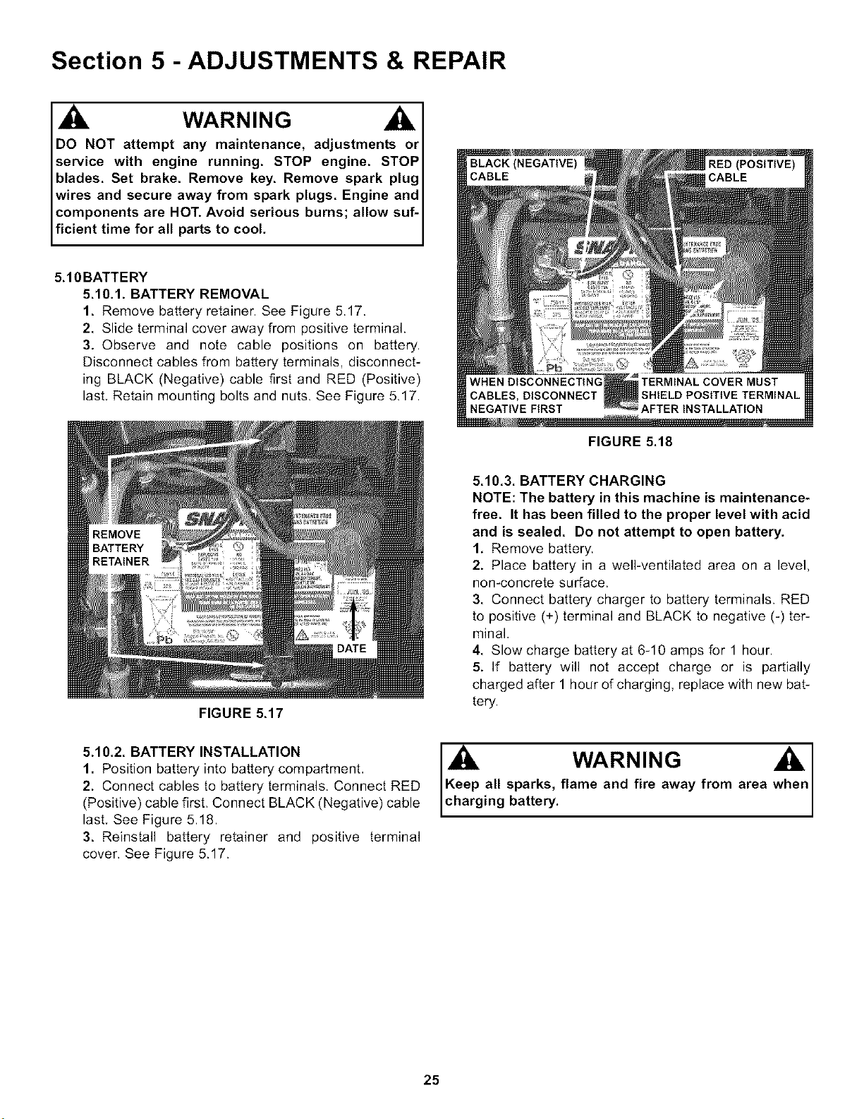
5.10.1. BATTERY REMOVAL
1. Remove battery retainer. See Figure 5.17.
2. Slide terminal cover away from positive terminal.
3. Observe and note cable positions on battery.
Disconnect cables from battery terminals, disconnect-
ing BLACK (Negative) cable first and RED (Positive)
last, Retain mounting bolts and nuts. See Figure 5.17.
FIGURE 5.17
FIGURE 5.18
5.10.3. BATTERY CHARGING
NOTE: The battery in this machine is maintenance-
free. It has been filled to the proper level with acid
and is sealed. Do not attempt to open battery.
1. Remove battery.
2. Place battery in a well-ventilated area on a level,
non-concrete surface.
3. Connect battery charger to battery terminals, RED
to positive (+) terminal and BLACK to negative (-) ter-
minal,
4. Slow charge battery at 6-10 amps for 1 hour,
5. If battery will not accept charge or is partially
charged after 1 hour of charging, replace with new bat-
tery,
5.10.2. BATTERY INSTALLATION
1. Position battery into battery compartment,
2. Connect cables to battery terminals. Connect RED
(Positive) cable first, Connect BLACK (Negative) cable
last, See Figure 5.18.
3. Reinstall battery retainer and positive terminal
cover. See Figure 5.17.
WARNING
Keep all sparks, flame and fire away from area
charg ng battery.
25
Section 5 -ADJUSTMENTS & REPAIR
5.11 HYDRAULIC SYSTEM, PURGING
After replacing or repairing hydraulic system compo-
nents, one or both of the wheel drives may net pull
properly. This is likely to be caused by air entrapped in
the system, If you experience a pulling issue after
completing repairs, perform the following procedure to
purge the air from one or both of the hydraulic drive
systems.
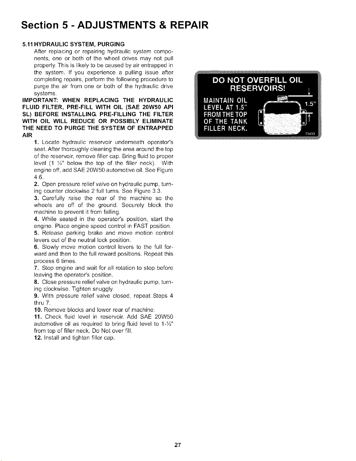
IMPORTANT: WHEN REPLACING THE HYDRAULIC
FLUID FILTER, PRE-FILL WITH OIL (SAE 20W50 API
SL) BEFORE INSTALLING PRE-FILLING THE FILTER
WITH OIL WILL REDUCE OR POSSIBLY ELIMINATE
THE NEED TO PURGE THE SYSTEM OF ENTRAPPED
AIR
1. Locate hydraulic reservoir underneath operator's
seat, After thoroughly cleaning the area around the top
of the reservoir, remove filler cap. Bring fluid to proper
level (1 _/2"below the top of the filler neck), With
engine off, add SAE 20W50 automotive oil. See Figure
4.6.
2. Open pressure relief valve on hydraulic pump, turn-
ing counter clockwise 2 full turns. See Figure 3.3.
3. Carefully raise the rear of the machine so the
wheels are off of the ground. Securely block the
machine to prevent it from falling.
4. While seated in the operator's position, start the
engine. Place engine speed control in FAST position.
5. Release parking brake and move motion control
levers out of the neutral lock position,
6. Slowly move motion control levers to the full for-
ward and then to the full reward positions. Repeat this
process 6 times.
7. Stop engine and wait for all rotation to stop before
leaving the operator's position,
8. Close pressure relief valve on hydraulic pump, turn-
ing clockwise. Tighten snuggly.
9. With pressure relief valve closed, repeat Steps 4
thru 7.
10. Remove blocks and lower rear of machine.
11. Check fluid level in reservoir. Add SAE 20W50
automotive oil as required to bring fluid level to 1J/2"
from top of filler neck. De Not over fill.
12. Install and tighten filler cap.
27

TROUBLESHOOTING
PROBLEM PROBABLE CAUSE CORRECTIVE ACTION
Starter Will Not 1. Battery dead. 1. Service battery.
Crank Engine 2. Blown fuse. 2. Replace fuse.
3. Electrical connections loose or corroded. 3. Clean and check connections for good contact.
4. Defective ignition switch. 4. Contact authorized SNAPPER dealer.
Engine Will 1. Blade engagement switch in the "ON" position. 1. Move blade engagement switch to "OFF".
Not Start 2. Park brake not set or Operator not seated. 2. Set park brake and Operator in Operator Seat.
3. Motion Controls not in Neutral Lock Position. 3. Place Motion Controls in Neutral Lock Position.
4. FueI tank empty. 4. Fill fueI tank with flesh fueI or switch tanks.
5. Engine needs choking. 5. Move choke control to "CHOKE" position.
6. Spark plug wire disconnected. 6. Place spark plug wire onto spark plug.
7. Battery weak or dead. 7. Service battery.
8. Faulty parking brake, blade or ignition switch. 8. Contact authorized SNAPPER dealer.
Engine Stalls 1. Operator not in seat. 1. Sit in operator's seat.
After Running 2. Choke control in the "CHOKE" position. 2. Move choke control to "OFF" position.
3. FueI tank empty. 3. Fill with fueI to proper leveI or switch tanks.
4. Engine air pre_cleaner and or air cleaner dirty. 4. Clean flee of alt debris.
5. Spark plug defective or gap set improperly. 5. Service spark plug.
6. FueI filter stopped up. 6. Replace fueI filter.
7. Water, debris or stale fueI in fueI system. 7. Drain and dean fueI system.
Engine Loses Power 1. Excessive load on engine. 1. Lessen toad.
2. Engine air pre_cleaner or air cleaner dirty. 2. Clean or replace filters.
3. Engine oil leveI low. 3. Fill with engine oil to proper leveI.
4. Engine cooling fins & air intake screen exces_ 4. Clean cooling fins, air intake screen of all debris.
siveIy dirty.
5. Spark plug faulty. 5. Service spark plug.
6. Water, debris or stale fueI in fueI system. 6. Drain and dean fueI system.
Engine Backfires 1. Throttte control set too "FAST". 1. Set throttle contro{ to "SLOW" and allow engine to idle.
When Turned To Then, turn key to "OFF".
"STOP"
Excessive Vibration 1. Damaged or bent mower blades. 1. Service mower blade(s).
2. Loose blade components. 2. Service and tighten loose parts.
3. Worn or damaged components. 3. inspect alt beIts and pulleys.
4. Loose or missing air lift (if equipped). 4. Replace air lifts. Tighten to proper torque.
(Trouble Shooting Continued on Next Page)
28

TROUBLESHOOTING
PROBLEM PROBABLE CAUSE CORRECTIVE ACTION
Machine Will Not Move 1. Motion Control Levers in the neutral "N" position. I. Move Motion Controls to desired speed position.
Loss Of Traction 2. Hydro. Pumps in roll release setting. !. Tighten reIlef valves.
3. Low transmission hydraulic oil level. }. Bring hydraulic oil to proper level.
4. Parking Brake engaged, l. Move parking brake to disengaged position.
5. Traction drive belt requires replacement. L Replace traction drive belt.
Blade(s) Not Cutting 1. Blade engagement switch in the "OFF" position. I. Move blade switch to the "ON" position.
2. Mower belt slipping. !. Adjust or replace mower belt.
3. Electric clutch not functioning. }. Contact authorized SNAPPER dealer.
Cutting Grass 1. Uneven tire pressure. I. Bring to proper pressure.
Improperly 2. Cutting height too low or high. !. Adjust cutting height.
3. Engine speed too stow. }. Move throttle control to "FAST" position.
4. Forward speed too fast. l. Move joystick to a slower speed.
5. Terraced cut, side to side. L Adjust side to side level.
6. Excessive deck pitch, front to rear. }. Adjust front to rear level.
7. Cutting blade(s) dull or damaged. . Sharpen cutting edges or replace blade(s).
8. Blade belt slipping. }. Adjust or replace blade belt.
9. Check electric clutch. ). Adjust to proper specifications.
10. Check gearbox for damage. I0. Contact authorized SNAPPER dealer.
Poor Grass Discharge 1. Engine speed too stow. I. Move throttle control to "FAST" position.
2. Forward speed too fast. !. Move joystick to a slower speed.
3. Grass is wet. }. Mow when grass is dry.
4. Excessively worn or damaged blade(s), l. Service mower blade(s).
5. Build up of grass clippings and debris under deck. L Clean deck.
6. Improper blade(s) installed on deck. }. Instatl proper SNAPPER blades.
7. Blade(s) installed improperly on deck. . Install blades properly.
Battery Will Not Charge 1. Poor cable connections. I. Clean cables and battery terminals.
2. Bad battery ceIt(s). !. Replace with new battery.
3. Faulty alternator. }. Contact engine manufacturer's dealer.
29
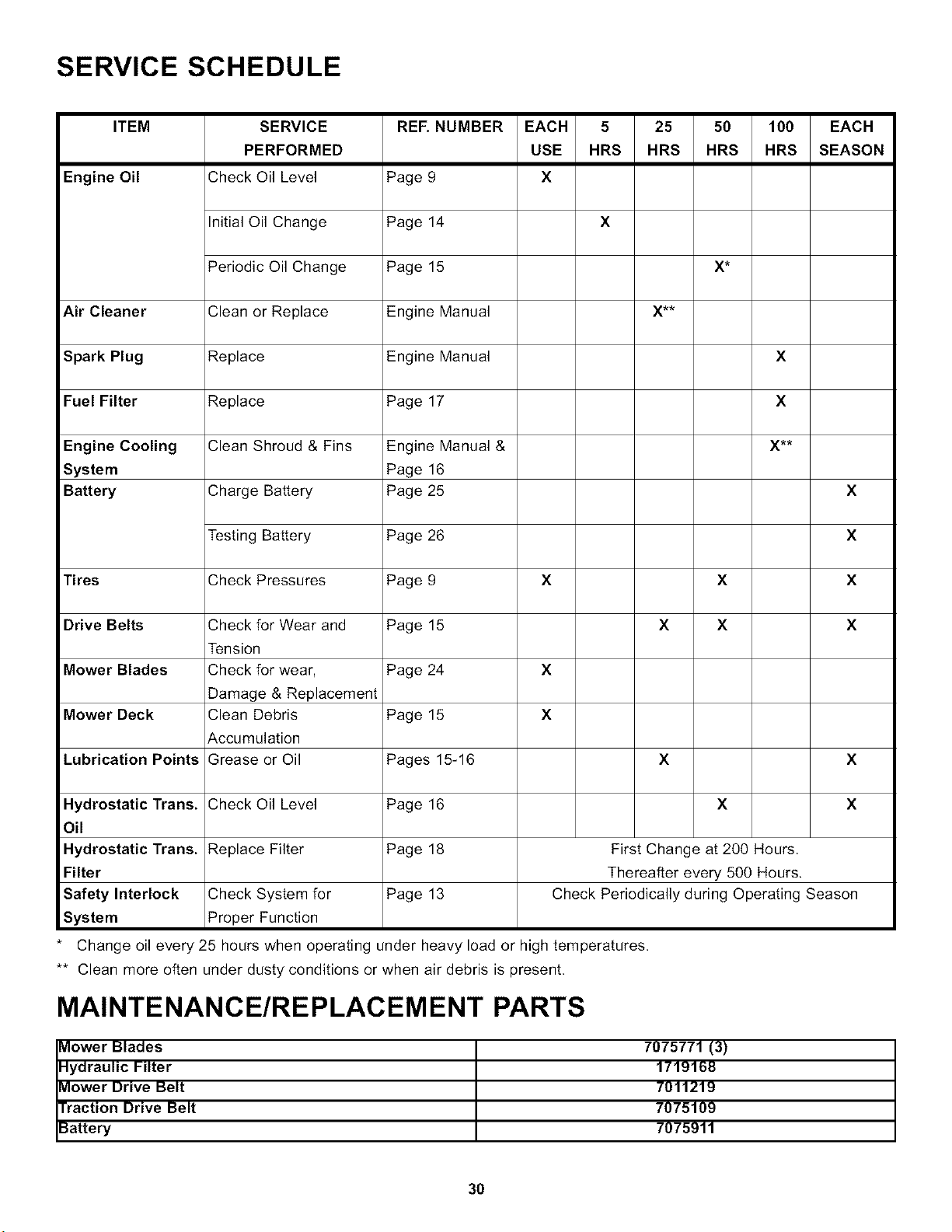
SERVICE SCHEDULE
ITEM SERVICE
PERFORMED
Engine Oil Check Oil Level
REF. NUMBER EACH 5 25 50 100 EACH
USE HRS HRS HRS HRS SEASON
Page 9 X
Initial Oil Change Page 14
X
Periodic Oil Change Page 15
X',_
Air Cleaner
Clean or Replace Engine Manual
Spark Plug Replace Engine Manual
X
Fuel Filter Replace Page 17
X
Engine Cooling
System
Battery
Clean Shroud & Fins
Charge Battery
Engine Manual &
Page 16
Page 25
X
Testing Battery Page 26
X
Tires
Check Pressures Page 9
X X X
Drive Belts
Mower Blades
Mower Deck
Lubrication Points
Check for Wear and Page 15
Tension
Check for wear, Page 24
Damage & Replacement
Clean Debris Page 15
Accumulation
Grease or Oil Pages 15-16
X
X
X
X
X X
X
Hydrostatic Trans.
Oil
Hydrostatic Trans.
Filter
Safety Interlock
System
Check Oil Level Page 16
X X
Replace Filter Page 18
Check System for Page 13
Proper Function
First Change at 200 Hours.
Thereafter every 500 Hours.
Check Periodically during Operating Season
Change oil every 25 hours when operating under heavy load or high temperatures.
** Clean more often under dusty conditions or when air debris is present.
MAINTENANCE/REPLACEMENT PARTS
Mower Blades
Hydraulic Filter
Mower Drive Belt
Traction Drive Belt
Battery
7075771 (3)
1719168
7011219
7075109
7075911
3O