Loading ...
Loading ...
Loading ...
Rinnai 21 HW_CF OIM
Location
NOTE
• DO NOT install water controllers near a heat source, such as a cook top, stove or oven� Heat,
steam, smoke and hot oil may cause damage�
• DO NOT install water controllers outdoors unless protection from water / dust ingress and
sunlight are provided�
• The water controller set as the MASTER water controller MUST NOT be installed in a
bathroom�
• DO NOT install water controllers in direct sunlight�
• DO NOT install water controllers against a metal wall unless the wall is earthed in accordance
with AN/NZS 3000�
• Water controllers MUST NOT be installed where chemicals such as benzene, alcohol,
turpentine, hydrogen sulphide, ammonia, chlorine or other similar chemicals are in use�
The Water controller is a water resistant device, however excessive exposure to water may result
in damage to the water controller� Durability is improved when positioned outside the shower
recess�
• AVOID direct exposure to water or steam as these conditions may cause a malfunction�
• Water controllers must be installed in shaded and clean locations. They should be tted out
of reach of children (suggested height from oor to be at least 1500 mm). Water controllers
MUST BE installed at least 400 mm above the highest part of a sink, basin or bath�
• When cleaning your water controller use ONLY a damp cloth and a mild detergent�
For water controller dimensions refer to "Table 1� Appliance Dimensions" and "Diagram 1�
Dimensions" on page 26�
Communication Cables
Wired water controllers operate at an extra low voltage (12 Volts DC) which is supplied from the water heater,
a 10 metre long communications cable is supplied for connection to the water heater� ONLY Rinnai supplied
communication cables may be used� Optional longer communication cabling is available from Rinnai�
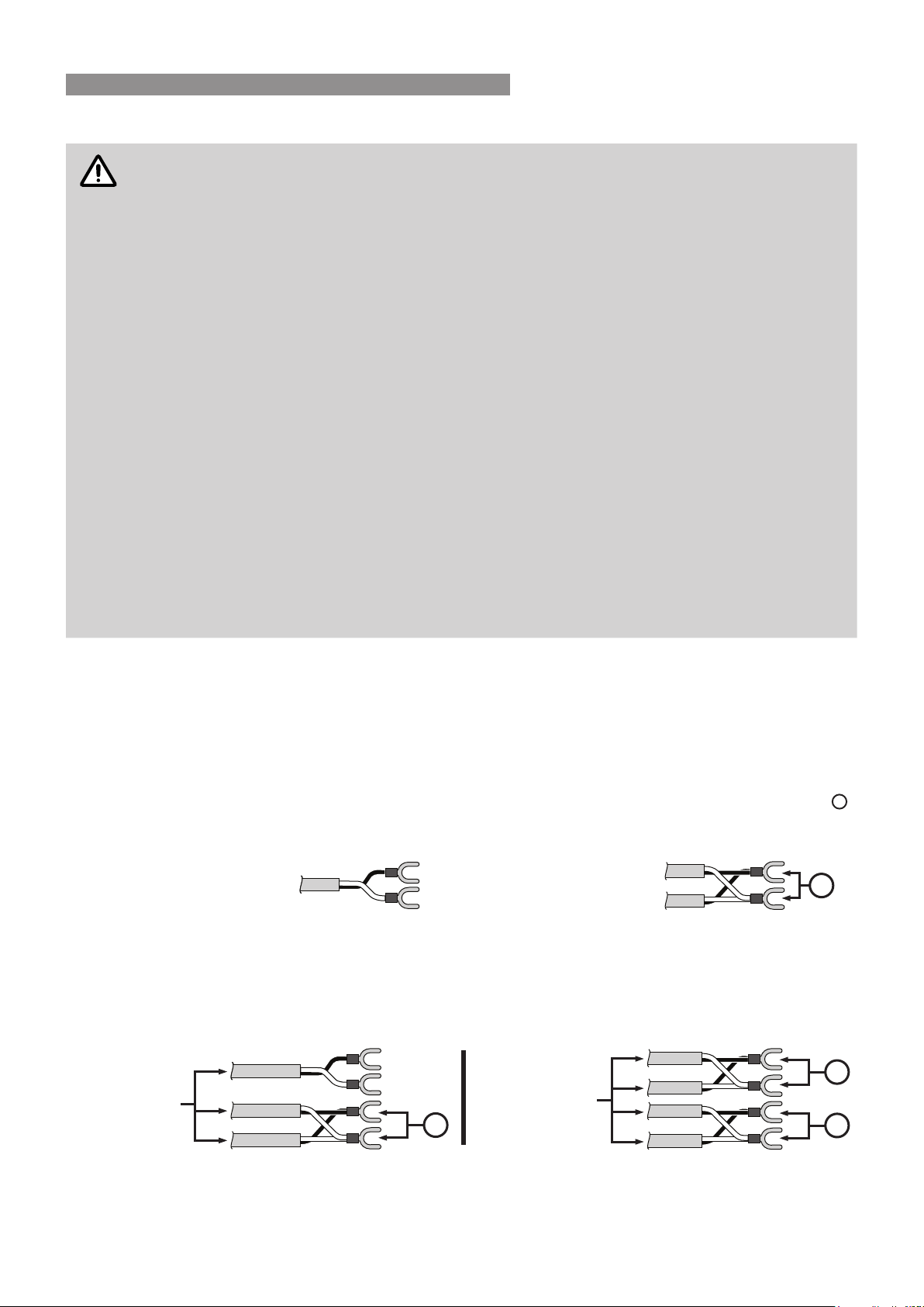
The water heater end of the cables are tted with spade terminals. Only two pairs of cables (4 spade connectors in
total) may be terminated. When attaching three or four cables it is necessary to join the cable terminals as follows:
For each pair cut off the existing spade connectors and re-terminate each pair into a new spade connector
A
(spade connectors are available from your local electrical component retailer) so that there are only two sets of
spade connectors (4 spade connectors in total) to be terminated.
Single cables can be used
when terminating up to two
communication cables.
Paired cables are to be used
when terminating three or
four communication cables.
A
Connecting One or Two Communication Cables
Follow steps 1 through 5 of "Communication Cable(s) & ’Ezi connect’" on page 22 to terminate the cables to the
water heater�
Connecting Three or Four Communication Cables
To connect three or four cables, separate all the cables to be tted into pairs.
Follow steps 1 through 5 of "Communication Cable(s) & ’Ezi connect’" on page 22 to terminate the joined cable
pairs to the water heater�
When
Terminating
Three Cables
When
Terminating
Four Cables
A
A
A
WATER CONTROLLER INSTALLATION
Loading ...
Loading ...
Loading ...