Loading ...
Loading ...
Loading ...
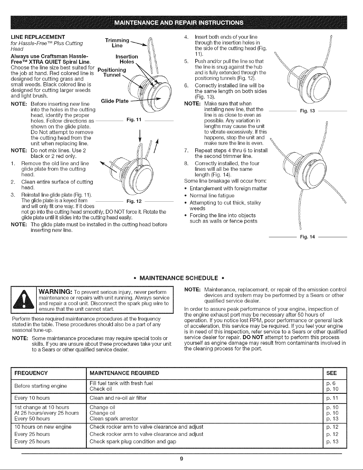
LiNE REPLACEMENT
Trimmim
for Hassle-Free TM Plus Cutting Line
Head
Always use Craftsman Hassle- insertion
Free TM XTRA QUIET Spiral Line. Holes
Choose the line size best suited for Positioning
the job at hand. Red colored line is Tunnel
designed for cutting grass and
small weeds. Black colored line is
designed for cutting larger weeds
and light brush.
NOTE: Before inserting new line
into the holes in the cutting
head, identify the proper
holes. Follow directions as
shown on the glide plate.
Do Not attempt to remove
the cutting head from the
unit when replacing line.
NOTE: Do not mix lines. Use 2
black or 2 red only.
1. Remove the old line and line
glide plate from the cutting
head.
2. Clean entire surface of cutting
head.
3. Reinstall line glide plate (Fig. 11).
The glide plate is a keyed item
and will only fit one way. If it does
Glide Plate
Fig. 11
Fig. 12
not go into the cLr[ting head smoothly, DO NOT force it. Rotate the
glide plate until it slides into the cutting head easily.
NOTE: The glide plate must be installed in the cutting head before
inserting new line.
4. Insert both ends d your line
through the insertion holes in
the side d the cutting head (Fig.
11).
5. Push and/or pull the line so that
the line is snug against the hub
and is fully extended through the
positioning tunnels (Fig. 12).
6. Correctly installed line will be
the same length on both sides
(Fig. 13).
NOTE: Make sure that when
installing new line, that the
line is as close to even as
possible. Any variation in
lengths may cause the unit
to vibrate excessively. If this
happens, stop the unit and
make sure the line is even.
7. Repeat steps 4 thru 6 to install
the second trimmer line.
8. Correctly installed, the four
lines will all be the same
length (Fig. 14).
Some line breakage will occur from:
• Entanglement with foreign matter
Normal line fatigue
Attempting to cut thick, stalky
weeds
Forcing the line into objects
such as walls or fence posts
Fig. 13
Fig. 14
* MAINTENANCE SCHEDULE =
J_ ARNING: To prevent serious injury, never perform
maintenance or repairs with unit running. Always service
and repair a cool unit. Disconnect the spark plug wire to
ensure that the unit cannot start.
Perform these required maintenance procedures at the frequency
stated in the table. These procedures should also be a part of any
seasonal tune-up.
NOTE: Some maintenance procedures may require special tools or
skills. If you are unsure about these procedures take your unit
to a Sears or other qualified service dealer.
NOTE: Maintenance, replacement, or repair of the emission control
devices and system may be performed by a Sears or other
qualified service dealer.
In order to assure peak performance of your engine, inspection of
the engine exhaust port may be necessary after 50 hours of
operation. If you notice lost RPM, poor performance or general lack
of acceleration, this service may be required. If you feel your engine
is in need of this inspection, refer service to a Sears or other qualified
service dealer for repair. DO NOT attempt to perform this process
yourself as engine damage may result from contaminants involved in
the cleaning process for the port.
FREQUENCY MAINTENANCE REQUIRED SEE
Before starting engine Fill fuel tank with fresh fuel p. 6
Check oil p. 10
Every 10 hours Clean and re-oil air filter p. 11
1st change at 10 hours Change oil p. 10
At 25 hours/every 25 hours Change oil p. 10
Every 50 hours Clean spark arrestor p. 13
10 hours on new engine Check rocker arm to valve clearance and adjust p. 12
Every 25 hours Check rocker arm to valve clearance and adjust p. 12
Every 25 hours Check spark plug condition and gap p. 13
g
Loading ...
Loading ...
Loading ...