Loading ...
Loading ...
Loading ...
11
WIRING
WARNING: To reduce the risk of re, electrical shock or personal injury, wire connectors
provided with this fan are designed to accept only one 12-gauge house wire and two lead wires from
the fan. If your house wire is larger than 12-gauge and there is more than one house wire to connect
to the two fan lead wires, consult an electrician for the proper size wire connectors to use.
CAUTION: Be sure the outlet box is properly grounded or that a ground (green or bare) wire is present.
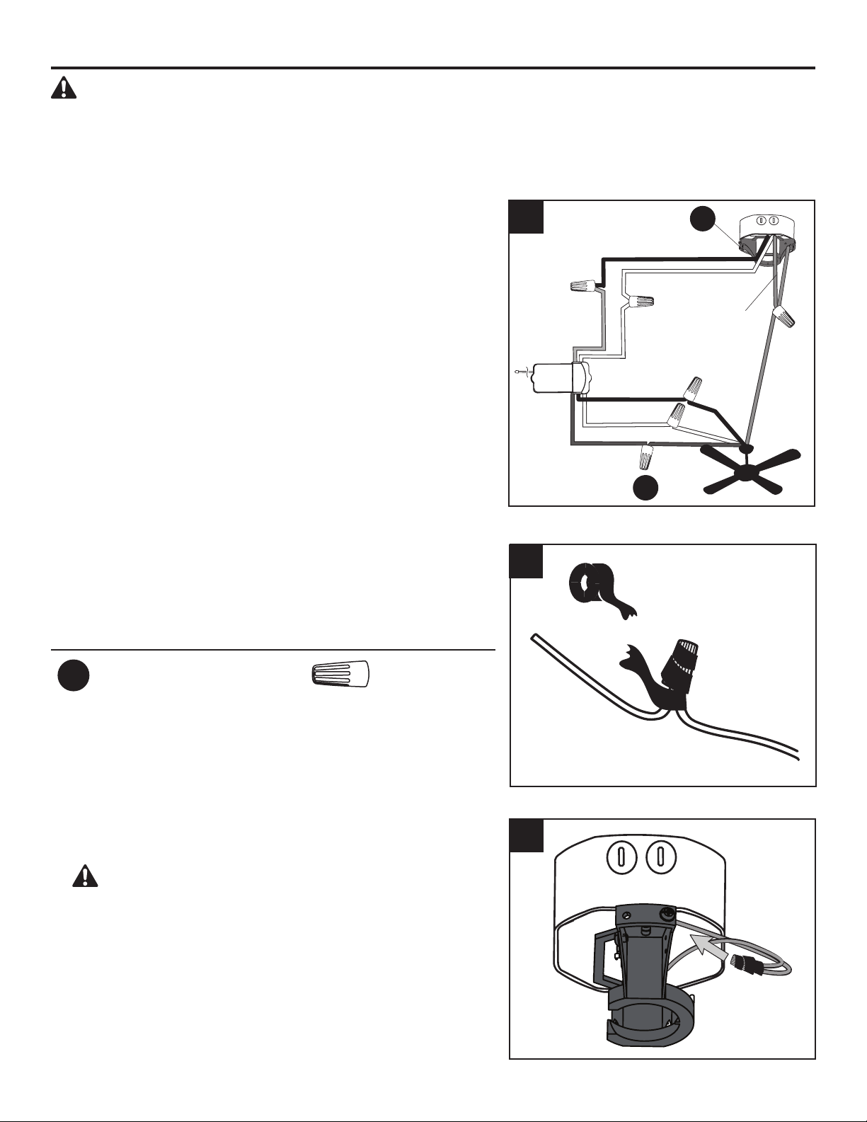
1. Secure all wiring connections together with wire connector
(AA) and the wire connectors from remote pack (Q)
according to the diagram and these steps:
• Connect the green wires from the downrod and mounting
bracket to the bare/green (ground) supply wire.
• Connect the Blue wire (FOR LIGHT) from the receiver to
the Blue fan wire.
• Connect the Black wire (TO MOTOR L) from the receiver
to the Black fan wire.
• Connect the White wire (TO MOTOR N) from the
receiver to the White fan wire.
• Connect the Black wire (AC IN L) from the receiver to the
Black (hot/power) supply wire.
• Connect the White (AC IN N) from the receiver to the
White (neutral) supply wire.
Important: After the connections have been made, the
connected wires should be turned upward and pushed
carefully up into the outlet box. Place the black and white
wire connections on opposite sides of the outlet box.
Hardware Used
AA
Wire Connector x 1
Black (hot/power)
White (neutral)
Bare/Green
(ground)
Red
White
White
White
Black
Blue
Blue
Black
Green
Green
Receiver
2. Wrap electrical tape (not included) around each
individual wire connector (AA) down to the wire.
3. Turn the spliced/taped wires upward and gently push the
wires and wire connectors (AA) into the outlet box.
WARNING: Ensure no bare wire or wire strands
are visible after making connections. Place the Green
and White wire connections on the opposite side of the
outlet box from the Black wire connections.
1
3
AA
D
2
Loading ...
Loading ...
Loading ...