_j_/_i_ Owner's Manual
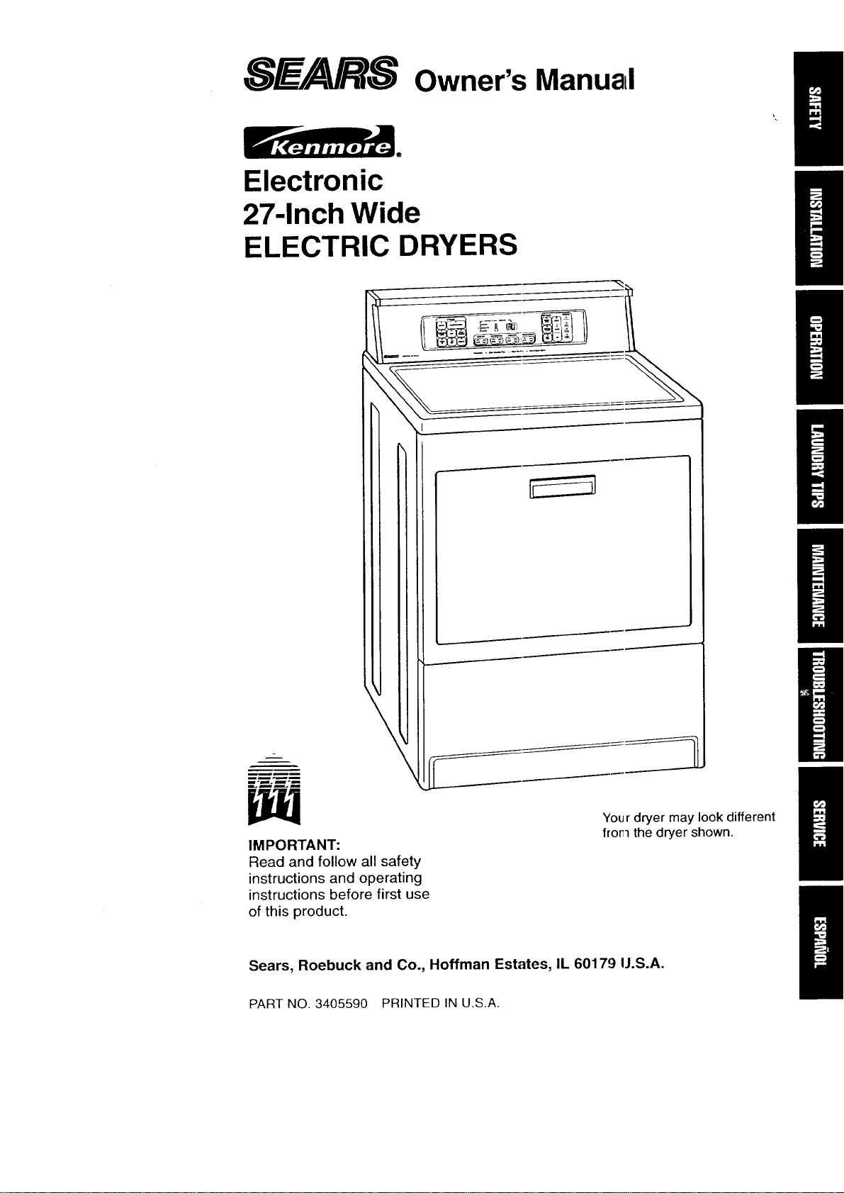
Electronic
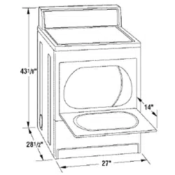
27-Inch Wide
ELECTRIC DRYERS
IMPORTANT:
Read and follow all safety
instructions and operating
instructions before first use
of this product.
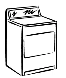
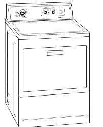
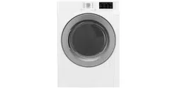
Your dryer may look different
frorl the dryer shown.
Sears, Roebuck and Co., Hoffman Estates, IL 60179 U.S.A.
PART NO. 3405590 PRINTED IN U.S.A.
BEFORE USING YOUR NEW DRYER 2
SEARS ELECTRIC DRYER WARRANTY
IMPORTANT SAFETY INSTRUCTIONS 3
INSTALLATION INSTRUCTIONS
4
OPERATING YOUR DRYER 19
LAUNDRY TIPS 28
CARING FOR YOUR DRYER 31
TROUBLESHOOTING 35
SEARS MAINTENANCE AGREEMENT
37
REQUESTING ASSISTANCE OR SERVIC E 38
Please read this manual. It will help you
install and operate your new Kenmore dryer
in the safest and most economical way.
For information about the care and
operation of Sears appliances call your
nearest Sears store. You will need the
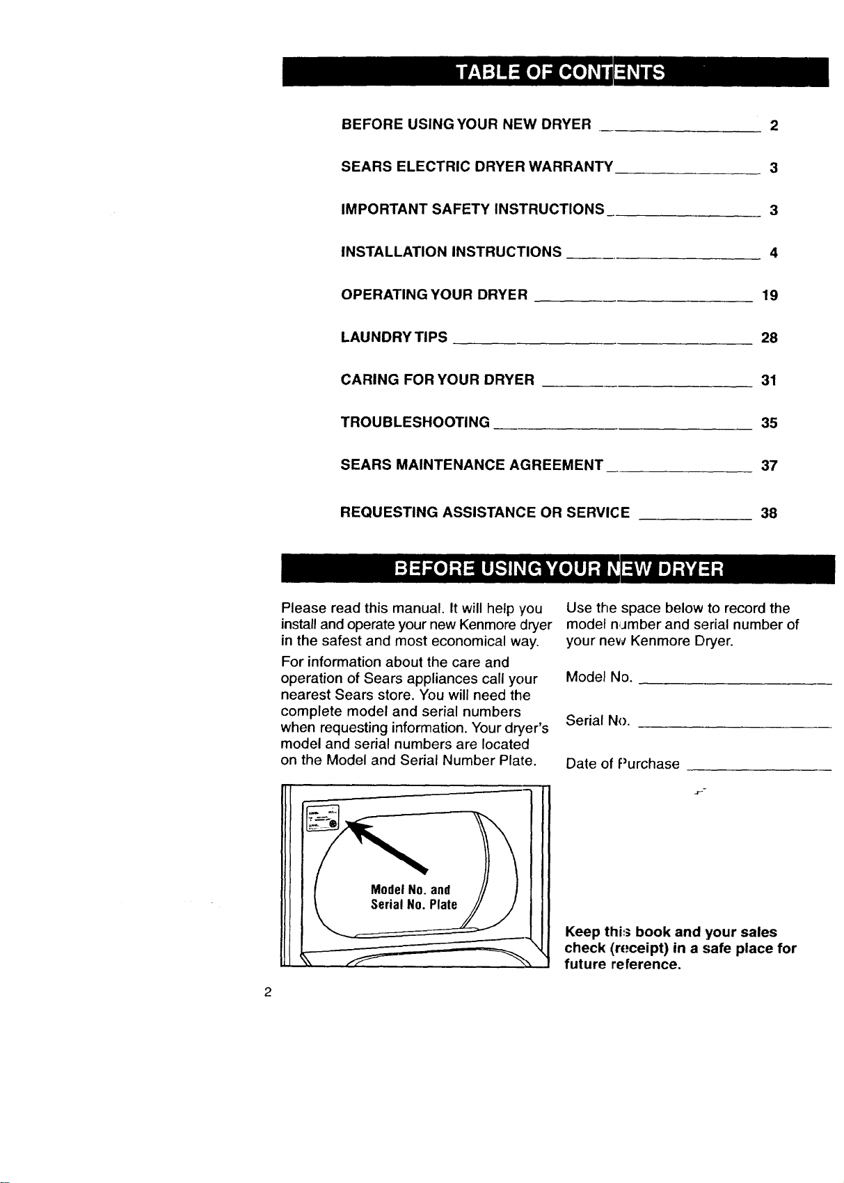
complete model and serial numbers
when requesting information. Your dryer's
model and serial numbers are located
on the Model and Serial Number Plate.
Use the space below to record the
model number and serial number of
your new Kenmore Dryer.
Model No.
Serial No.
Date of Purchase
.r"
Keep this book and your sales
check (receipt) in a safe place for
future reference.
FULL1-YEARWARRANTY
ONMECHANICALAND
ELECTRICALPARTS
For one year from the date of purchase,
when the dryer is installed and operated
according to the instructions in the Owner's
Manual, Sears will repair or replace any
mechanical or electrical parts in this dryer,
if defective in material or workmanship.
If the dryer is subjected to other than
private family use, the above warranty
coverage is effective for only 90 days.
WARRANTY SERVICE IS AVAILABLE
BY CONTACTING THE NEAREST
SEARS SERVICE CENTER IN THE"
UNITED STATES.
This warranty applies only while this
product is in use in the United States.
This warranty gives you specific legal
rights, and you may also have other
rights which wiry from state to state.
Sears Roebuck and Co., Dept. 817WA,
Hoffman Estales, IL 60179.
NOTE: Exhau:sting your dryer with
plastic duct may not be covered by your
manufacturer% warranty. Pages 14-17
of this Owner'=_ Manual describe the
complete exhaust requirements for
this dryer.
m
YOUR SAFETY IS IMPORTANT TO US.
WARNING: To reduce the risk of fire,
electric shock, or injury to persons when
using your dryer, follow basic precautions,
including the following:
• Read all instructions before using
the dryer.
• Do not dry articles that have been
previously cleaned in, washed in, soaked
in, or spotted with gasoline, dry-cleaning
solvents, other flammable or explosive
substances as they give off vapors that
could ignite or explode.
• Do not allow children to play on or in
the dryer. Close supervision of children
is necessary when the dryer is used
near children.
• Before the dryer is removed from service
or discarded, remove the door to the
drying compartment.
• Do not reach into the dryer if the drum
is moving.
• Do not install or store this dryer where
it will be exposed to the weather.
• Do not tamper with controls.
• Do not repair or replace any part of the
dryer or attempt any servicing unless
specifically recommended in the user-
maintenance, instructions or in published
user-repair_nstructions that you under-
stand and have the skills to carry out.
• Do not use faoric softeners or products
to eliminate static unless recommended
by the manufacturer of the fabric softener
or product.
• Do not use heat to dry articles containing
foam rubber ¢,rsimilarly textured rubber-
like materials.
• Clean lint screen before or after each
load.
• Keep area around the exhaust opening
and adjacent ',surrounding areas free from
the accumulation of lint, dust, and dirt.
• The interior of the machine and exhaust
duct should be cleaned periodically by
qualified servise personnel.
This guide contains safety statements
under warning symbols. Please pay
special attention to the warning boxes
similar to the one below and follow
any instructions given.
The inform_qtion in this box will
alert you to such dangers as fire,
electrical shock, burns and
personal injury.
SAVE THESE INSTRUCTIONS 3
IMPORTANT:
Observe all governing codes
and ordinances.
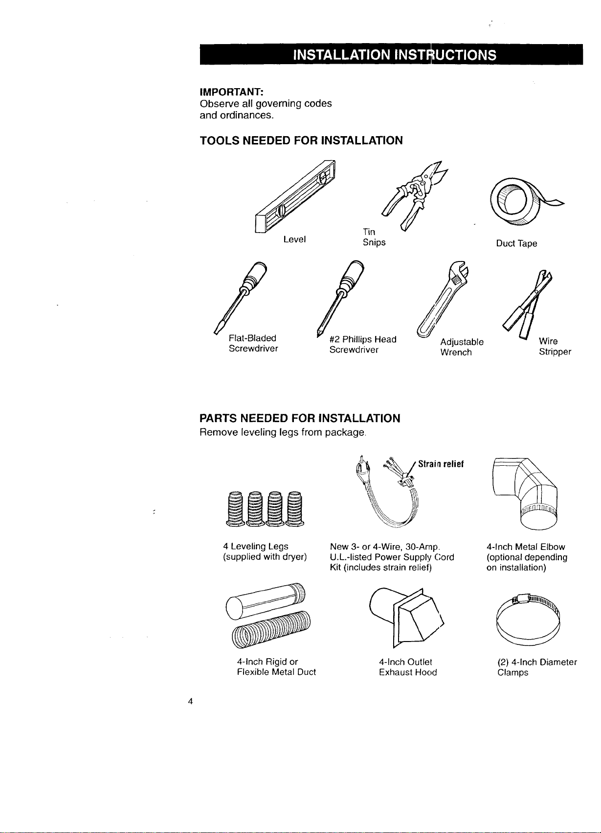
TOOLS NEEDED FOR INSTALLATION
S
Level
Tin
Snips
Flat-Bladed
Screwdriver
Adjustable
Wrench
Duct Tape
Wre
Stripper
PARTS NEEDED FOR INSTALLATION
Remove leveling legs from package.
4 Leveling Legs
(supplied with dryer)
New 3- or 4-Wire, 30-Amp.
U.L.-listed Power Supply Cord
Kit (includes strain relief)
relief
4-1rnch Metal Elbow
(optional depending
on installation)
4-Inch Rigid or
Flexible Metal Duct
4-Inch Outlet
Exhaust Hood
O
(2) 4-Inch Diameter
Clamps
LOCATING YOUR DRYER -
STANDARD INSTALLATION
Selecting the proper location
for your dryer makes installation
easier and gives you the best
drying performance.
Protect from the weather. Proper
operation of dryer cycles requires
temperatures above 45°E At lower
temperatures, the dryer may not shut
off at the end of automatic cycles.
Drying times will be extended.
Check code requirements. Some
codes limit or do not permit installation
of clothes dryers in garages, closets,
mobile homes or sleeping quarters.
Contact your local building inspector.
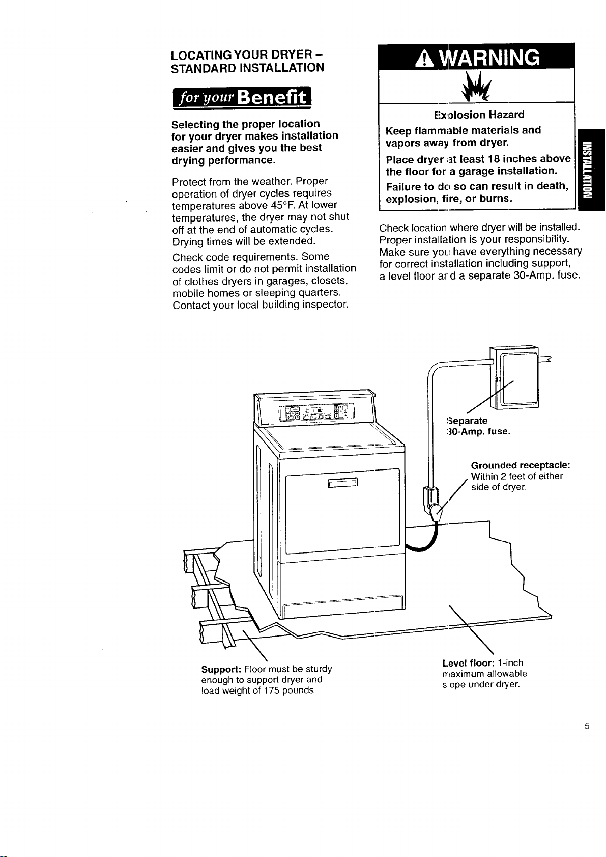
Explosion Hazard
Keep flammable materials and
vapors away' from dryer.
Place dryer ;_t least 18 inches above
the floor for a garage installation.
Failure to do so can result in death,
explosion, fire, or burns.
Check location where dryer will be installed.
Proper installation is your responsibility.
Make sure you have everything necessary
for correct installation including support,
a level floor and a separate: 30-Amp. fuse.
/ :
----l._
Support: Floor must be sturdy Level floor: 1-inch
enough to support dryer and maximum allowable
load weight of 175 pounds, s ope under dryer.
DOOR CLEARANCES AND
RECESSED AREA INSTRUCTIONS
Location must be large enough to fully
open dryer door.
This dryer may be installed in a recessed
area or closet.
Exhausting your dryer indoors is Not
recommended. The moisture and lint
indoors may cause:
• Lint to gather inside and around the
dryer and be a fuel for a fire.
• Moisture damage to woodwork, furni-
ture, paint, wallpaper, carpet, etc.
• Housecleaning problems and possible
health problems.
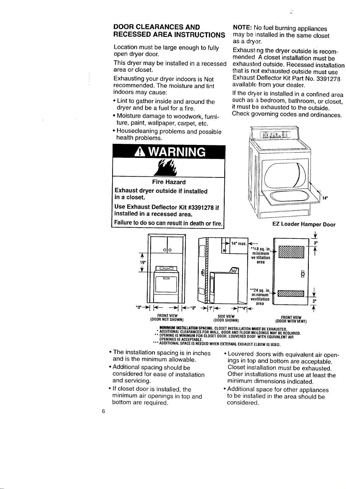
Fire Hazard
Exhaust dryer outside if installed
in a closet.
Use Exhaust Deflector Kit #3391278 if
installed in a recessed area.
Failure to do so can result in death or fire,
19-i
_f_
*0"---_
DO
NOTE: hiDfuel burning appliances
may be installed in the same closet
as a dryer.
Exhaustng the dryer outside is recom-.
mended A closet installation must be
exhausted outside. Recessed installatio_
that is not exhausted outside must use
Exhaust Deflector Kit Part No. 3391278
available, from your dealer.
If the dryer is installed in a confined area
such as .abedroom, bathroom, or closet,
it must be exhausted to the outside.
Check governing codes and ordinances.
SIDEVIEW
(DOORSHOWN)
EZ Loader Hamper Door
**L8 sq. in:_
mlnlmLIm
ve ltilation
area
**24 sq. in.
minimum"
ve:ttilation
area
.,,(-
FRONTVIEW FRONTVIEW
(DOORNOTSHOWN) (DOORWITH VENT}
MINIMUMINSTALLATIONSPACING,CLOSETINSTALLATIONMUSTBEEXHAUSTED.
* ADDITIONALCLEARANCESFORWALL,DOORANDFLOORMOLDINGSMAYBEREQUIRED.
** OPENINGIS MINIMUM FORCLOSE'[DDOR.LDUVEREDDODFWITH EQUIVALENTAIR
OPENINGSIS ACCEPTABLE.
*** ADDITIONALSPACEISNEEDEDWHENEXTERNALEXHAUSTELBOWISUSED.
• The installation spacing is in inches
and is the minimum allowable.
• Additional spacing should be
considered for ease of installation
and servicing.
• If closet door is installed, the
minimum air openings in top and
bottom are required.
3"
• Louvered :loors with equivalent air open-
ings in top and bottom are acceptable.
Closet installation must be exhausted.
Other installations must use at least the
minimum dimensions indicated.
, Addition.al space for other appliances
to be installed in the area should be
considered.
INSTALL LEVELING LEGS
Leveling your dryer correctly will
reduce oDe_ating noise and provide
improved drying performance.
STEP 1. Take two of the cardboard
corners from the carton. Place them
on the floor in back of the dryer.
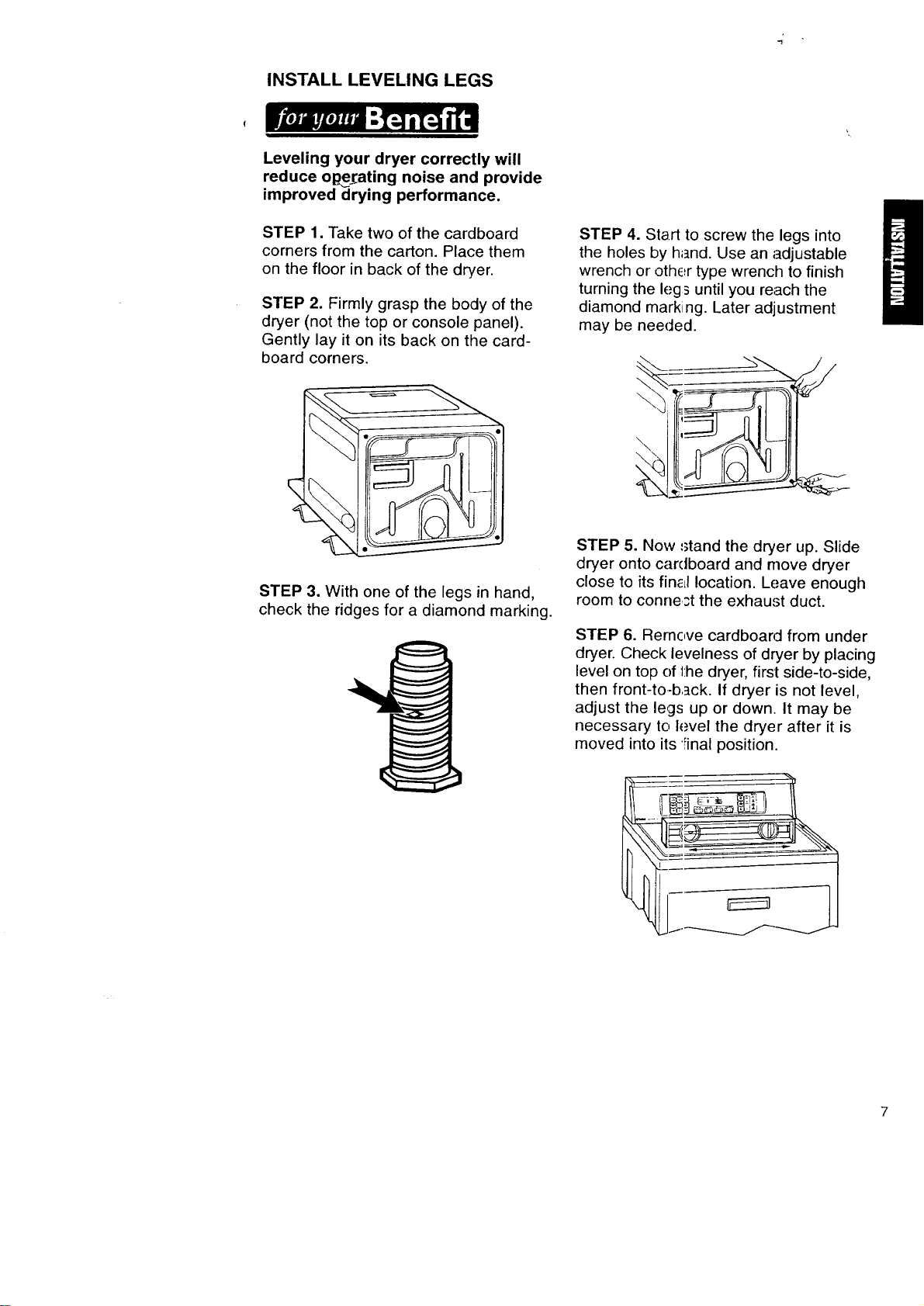
STEP 2. Firmly grasp the body of the
dryer (not the top or console panel).
Gently lay it on its back on the card-
board corners.
STEP 3. With one of the legs in hand,
check the ridges for a diamond marking.
STEP 4. Start to screw the legs into
the holes by h_nd. Use an adjustable
wrench or othc_rtype wrench to finish
turning the leg_ until you reach the
diamond marking. Later adjustment
may be needed.
STEP 5. Now _tand the dryer up. Slide
dryer onto cardboard and move dryer
close to its finial location. Leave enough
room to conne,st the exhaust duct.
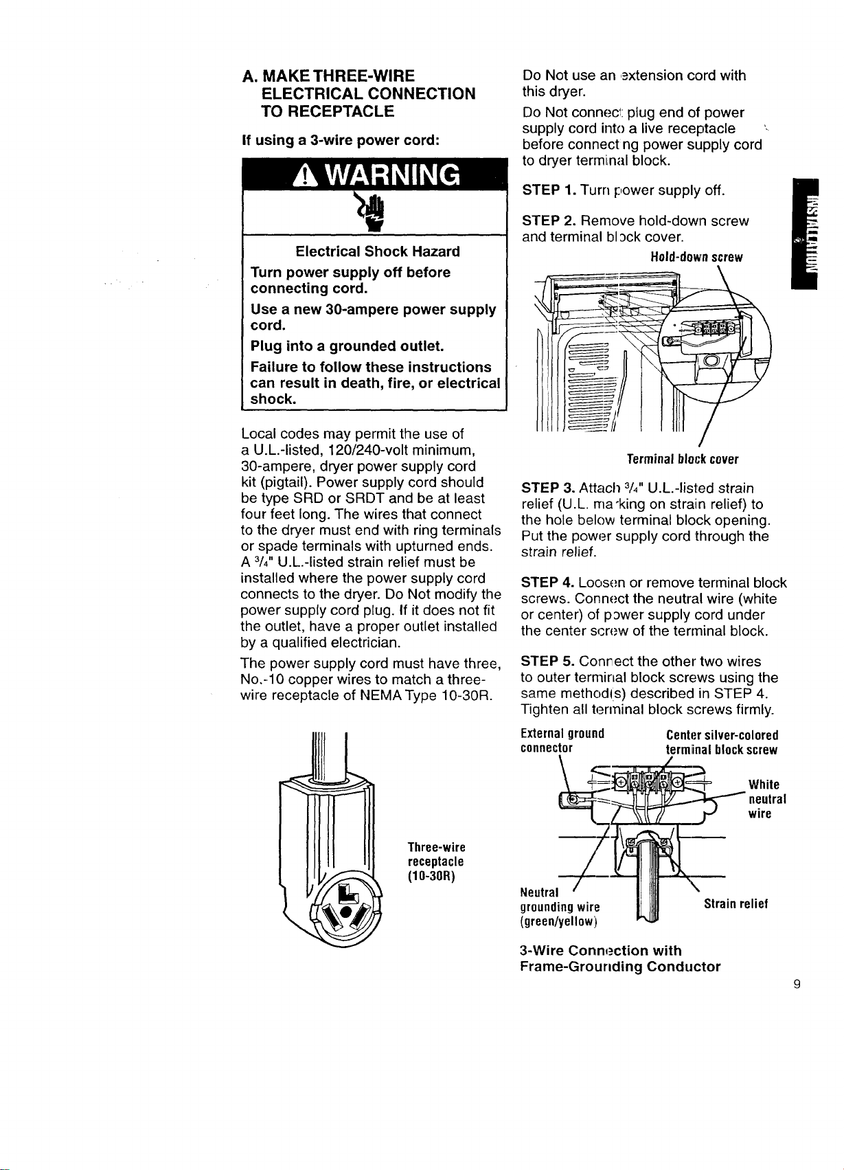
STEP 6. Rernc,ve cardboard from under
dryer. Check levelness of dryer by placing
level on top of 1:hedryer, first side-to-side,
then front-to-b.]ck. If dryer is not level,
adjust the legs up or down. It may be
necessary to I_.,vel the dryer after it is
moved into its Final position.
7
MAKE ELECTRICAL CONNECTION
It is your responsibility:
• To contact a qualified electrical installer.
• To assure that the electrical installation
is adequate and in conformance with
National Electrical Code, ANSI/NFPA
70 - latest edition* and all local codes
and ordinances.
*Copies of the standards listed above
may be obtained from:
National Fire Protection Association
Batterymarch Park
Quincy, Massachusetts 02269
ELECTRICAL REQUIREMENTS
The proper electrical connection
ensures a safe installation that
meets local code requirements.
This dryer is manufactured with the
3-wire irame-grounding conductor
connecLed to the NEUTRAL (center)
of the wiring harness of the terminal
block. Do Not have a fuse in the
neutral or grounding circuit. A fuse
in the n_=utral or grounding circuit
could result in an electrical shock.
If local ('odes do not permit this
type of I;onnection, we recommend
a "Four-Wire Connection'.'
A three-wire or four-wire, single phase
120/2.4C-volt, 60-Hz, AC-only, electrical
supply (or three-wire or four-wire,
120/208-volt if specified on serial/rating
plate) is required on a separate 30-ampere
circuit, fused on both sides of the line.
A time-celay fuse or circuit breaker is
recommended.
A wiring diagram is located inside the
console or on the inside of the lower
front panel of dryer.
WARNING: This appliance must be
grounded. In the event of malfunction
or breakdown, grounding will reduce the
risk of electric shock by providing a path
of least resistance for electric current.
ELECTRICAL CONNECTION OPTIONS
If Your Home Has:
A 3-wire electrical receptacle
(NEMA Type 10-30R)
And You Will Be Connecting To:
A U.L.-listed 120/240-volt minimum,
30-amp., dryer power supply cord.*
3-wire direct
(NEMA Type 10-30R)
GoTo
This Page
JL
A 4-wire electrical receptacle
(NEMA Type 14-30R)
4-wire direct
(NEMA Type 14-30R)
9-A
A fused disconnecl or circuit breaker box* 10 - B
A U.L.-listed 120/240-volt minimum,
30-amp., dryer power supply cord.
11 -C
*If local codes do not permit the connection of a frame-grounding conductor
to the neutral wire, see the instructions on page 11.
A fused disconnect or circuit breaker box. 13 - D
A. MAKE THREE-WIRE
ELECTRICAL CONNECTION
TO RECEPTACLE
If using a 3-wire power cord:
Electrical Shock Hazard
Turn power supply off before
connecting cord.
Use a new 30-ampere power supply
cord.
Plug into a grounded outlet.
Failure to follow these instructions
can result in death, fire, or electrical
shock.
Local codes may permit the use of
a U.L.-listed, 120/240-volt minimum,
30-ampere, dryer power supply cord
kit (pigtail). Power supply cord should
be type SRD or SRDT and be at least
four feet long. The wires that connect
to the dryer must end with ring terminals
or spade terminals with upturned ends.
A 3/4"U.L.-listed strain relief must be
installed where the power supply cord
connects to the dryer. Do Not modify the
power supply cord plug. If it does not fit
the outlet, have a proper outlet installed
by a qualified electrician.
The power supply cord must have three,
No.-10 copper wires to match a three-
wire receptacle of NEMAType 10-30R.
Three-wire
receptacle
(10-30R)
Do Not use an ,_xtension cord with
this dryer.
Do Not connect plug end of power
supply cord into a live receptacle '-
before connect ng power supply cord
to dryer terminal block.
STEP 1. Turn _:,ower supply off.
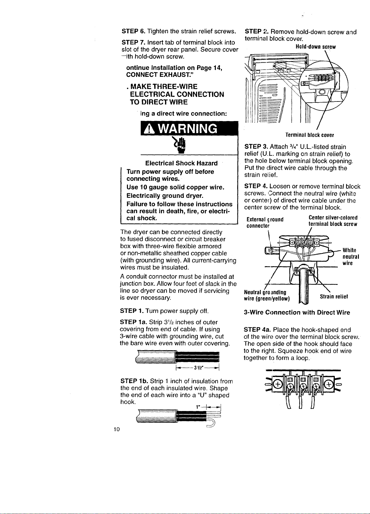
STEP 2. Remove hold-down screw
and terminal bl ock cover.
Hold-downscrew
Terminalblockcover
STEP 3. Attach 3/4"U.L.-listed strain
relief (U.L. ma-king on strain relief) to
the hole below terminal block opening.
Put the power supply cord through the
strain relief.
STEP 4. Loosen or remove terminal block
screws. Connect the neutral wire (white
or center) of power supply cord under
the center screw of the terminal block.
STEP 5. Conrect the other two wires
to outer terminal block screws using the
same method(s) described in STEP 4.
Tighten all terminal block screws firmly.
Externalground
connector
Centersilver-colored
terminalblockscrew
White
neutral
wire
Neutral
grounding wire
(green/yellow)
Strain relief
3-Wire Connection with
Frame-Grounding Conductor
STEP 6. Tighten the strain relief screws.
STEP 7. Insert tab of terminal block into
slot of the dryer rear panel. Secure cover
•"ith hold-down screw.
ontinue Installation on Page 14,
CONNECT EXHAUST."
• MAKE THREE-WIRE
ELECTRICAL CONNECTION
TO DIRECT WIRE
ing a direct wire connection:
Electrical Shock Hazard
Turn power supply off before
connecting wires.
Use 10 gauge solid copper wire.
Electrically ground dryer.
Failure to follow these instructions
can result in death, fire, or electri-
cal shock.
The dryer can be connected directly
to fused disconnect or circuit breaker
box with three-wire flexible armored
or non-metallic sheathed copper cable
(with grounding wire). All current-carrying
wires must be insulated.
A conduit connector must be installed at
junction box. Allow four feet of slack in the
line so dryer can be moved if servicing
is ever necessary.
STEP 1. Turn power supply off.
STEP la. Strip 31/2inches of outer
covering from end of cable. If using
3-wire cable with grounding wire, cut
the bare wire even with outer covering.
3v2"--
STEP lb. Strip 1 inch of insulation from
the end of each insulated wire. Shape
the end of each wire into a "U" shaped
hook.
lO
STEP ;t. Remove hold-down screw and
terminal block covet'.
Hold-downscrew
Terminalblockcover
STEP 3. Attach 3/4"IJ.L.-listed strain
relief (U.L. marking on strain relief) to
the hole below terminal block opening.
Put the direct wire cable through the
strain relief.
STEP 4. Loosen or remove terminal block
screw,,;. Connect the neutral wire (white
or center) of direct wire cable under the
center screw of the terminal block.
External_round
connector
Centersilver-colored
terminalblockscrew
White
neutral
wire
Neutralgrounding
wire(green/yellow)
Strainrelief
3-Wire Connection with Direct Wire
STEP 4a. Place the hook-shaped end
of the wire over the terminal block screw.
The open side of the hook should face
to the right. Squeeze hook end of wire
together tc) form a loop.
STEP5.Connecttheothertwowires
toouterterminalblockscrewsusingthe
samemethod(s)describedin STEP4a.
Tightenallterminalblockscrewsfirmly.
STEP6.Tightenthestrainreliefscrews.
STEP7.Inserttabofterminalblock
coverintoslotofthedryerrearpanel.
Securecoverwithhold-downscrew.
Continue Installation on Page 14,
"CONNECT EXHAUST."
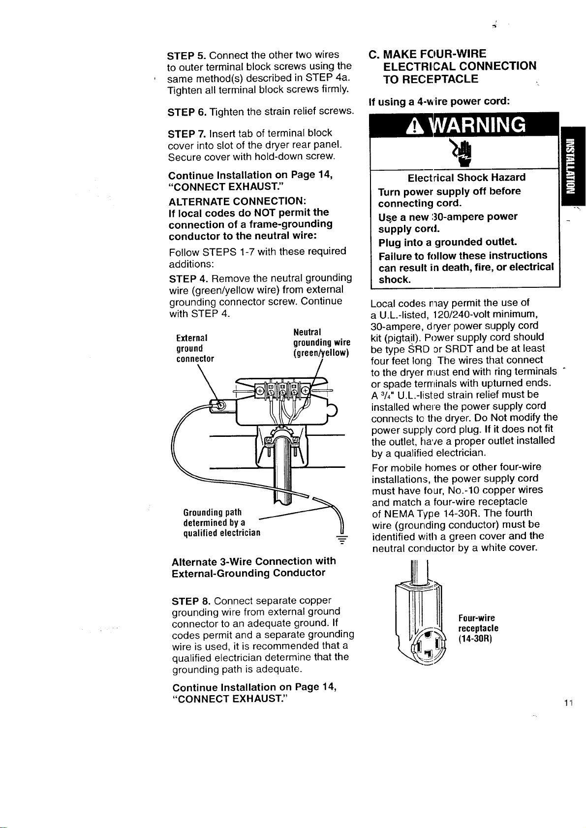
ALTERNATE CONNECTION:
If local codes do NOT permit the
connection of a frame-grounding
conductor to the neutral wire:
Follow STEPS 1-7 with these required
additions:
STEP 4. Remove the neutral grounding
wire (green/yellow wire) from external
grounding connector screw. Continue
with STEP 4.
External Neutral
ground groundingwire
connector (green/yellow)
Groundingpath _..-__
determinedbya
qualifiedelectrician
Alternate 3-Wire Connection with
External-Grounding Conductor
STEP 8. Connect separate copper
grounding wire from external ground
connector to an adequate ground. If
codes permit and a separate grounding
wire is used, it is recommended that a
qualified electrician determine that the
grounding path is adequate.
Continue Installation on Page 14,
"CONNECT EXHAUST."
C. MAKE FOUR-WIRE
ELECTRICAL CONNECTION
TO RECEPTACLE
If using a 4-wire power cord:
Electrical Shock Hazard
Turn power supply off before
connecting cord.
Us.e a new 30-ampere power
supply cord.
Plug into a grounded outlet.
Failure to follow these instructions
can result in death, fire, or electrical
shock.
Local code.,; nay permit the use of
a U.L.-listed, 120/240-volt minimum,
30-ampere, dryer power supply cord
kit (pigtail). Power supply cord should
be type ,_F{O or SRDT and be at least
four feet long The wires that connect
to the dryer must end with ring terminals °
or spade terminals with upturned ends.
A 3/4"U.L.-listed strain relief must be
installed where the power supply cord
connects to the dryer. Do Not modify the
power supply cord plug. If it does not fit
the outlet, have a proper outlet installed
by a qualified electrician.
For mobile homes or other four-wire
installations, the power supply cord
must have four, No.-10 copper wires
and match a four-wire receptacle
of NEMA Type 14-30R. The fourth
wire (grounding conductor) must be
identified with a green cover and the
neutral conductor by a white cover.
Four-wire
receptacle
(14-30R)
Do Not use an extension cord with
this dryer.
Do Not connect plug end of power
supply cord into a live receptacle before
connecting power supply cord to dryer
terminal block.
STEP 1. Turn power supply off.
STEP 2. Remove hold-down screw
and terminal block cover.
Hold-down
screw
Terminalblock
cover
STEP 3. Attach 3/4"U.L.-listed strain
relief (U.L. marking on strain relief) to
the hole below terminal block opening.
Put the power supply cord through
the strain relief.
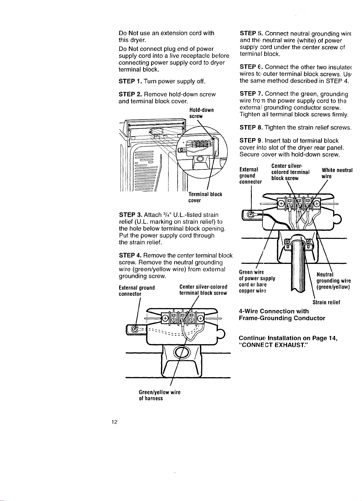
STEP 4. Remove the center terminal block
screw. Remove the neutral grounding
wire (green/yellow wire) from external
grounding screw.
Externalground
connector
Center silver-colored
terminal blockscrew
STEP 5. Connect neutral grounding wir_
and the neutral wire. (white) of power
supply cord under the center screw of
terminal block.
STEP El.Connect the other two insulate(
wires to outer terminal block screws. Us_
the same method described in STEP 4.
STEP 7. Connect the green, grounding
wire fro'n the power supply cord to the
externar grounding conductor screw.
Tighten all terminal [)lock screws firmly.
STEP 8. Tighten the strain relief screws.
STEP 9, Insert tab of terminal block
cover inLo slot of the dryer rear panel.
Secure oover with hold-down screw.
Centersilver-
External coloredterminal Whiteneutral
ground blockscrew wire
connector
Green wire Neutral
ofpower sllpply groundingwire
cord or bare (green/yellow)
copperwire
Strainrelief
4-Wire Connection with
Frame-.Grounding Conductor
Continue Installation on Page 14,
"CONNECT EXHAUST."
Green/yellowwire
ofharness
12
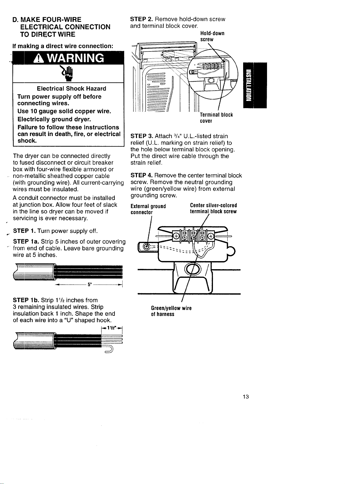
D. h/lAKE FOUR-WIRE STEP 2. Remove hold-down screw
ELECTRICAL CONNECTION and terminal block cover.
TO DIRECT WIRE H01d-d0wn
screw
If making a direct wire connection:
Electrical Shock Hazard
Turn power supply off before
connecting wires.
Use 10 gauge solid copper wire. Terminalblock
Electrically ground dryer. cave,
Failure to follow these instructions
can result in death, fire, or electrical STEP 3, Attach 3/4"U.L.-listed strain
shock, relief (U.L. marking on strain relief) to
the hole below terminal block opening.
The dryer can be connected directly
to fused disconnect or circuit breaker
box with four-wire flexible armored or
non-metallic sheathed copper cable
(with grounding wire). All current-carrying
wires must be insulated.
A conduit connector must be installed
at junction box. Allow four feet of slack
in the line so dryer can be moved if
servicing is ever necessary.
Put the direct wire cable through the
strain relief.
STEP 4. Remove the center terminal block
screw. Remove the neutral grounding
wire (green/yellow wire) from external
grounding screw.
Externalground
connector
Centersilver-colored
terminalblockscrew
STEP 1. Turn power supply off.
B-'
STEP la. Strip 5 inches of outer covering
_' from end of cable. Leave bare grounding
wire at 5 inches.
STEP lb. Strip 11/2inches from
3 remaining insulated wires. Strip
insulation back 1 inch. Shape the end
of each wire into a "U" shaped hook.
_--_-1l/z".-_-I
Green/yellowwire
ofharness
13
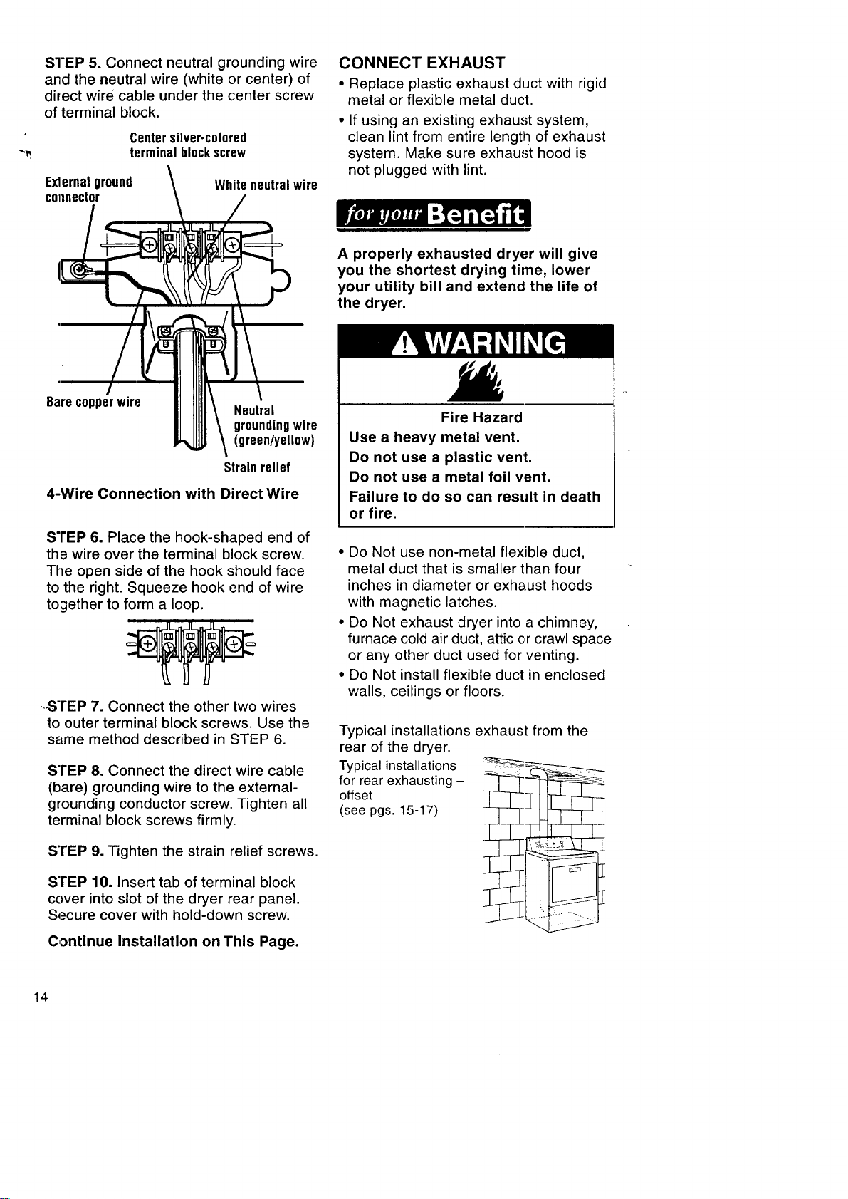
STEP 5. Connect neutral grounding wire
and the neutral wire (white or center) of
direct wire cable under the center screw
of terminal block.
Centersilver-colored
terminalblockscrew
Exl:ernalground
COl,lnector
Whiteneutralwire
CONNECT EXHAUST
• Replace plastic exhaust duct with rigid
metal or flexible metal duct,
• If using an existing exhaust system,
clean lint from entire length of exhaust
system. Make sure exhaust hood is
not plugged with lint.
A properly exhausted dryer will give
you the shortest drying time, lower
your utility bill and extend the life of
the dryer.
Barecopperwire Neutral
groundingwire
(green/yellow)
Strainrelief
4-Wire Connection with Direct Wire
STEP 6. Place the hook-shaped end of
the wire over the terminal block screw.
The open side of the hook should face
to the right. Squeeze hook end of wire
together to form a loop.
STEP 7. Connect the other two wires
to outer terminal block screws. Use the
same method described in STEP 6.
STEP 8. Connect the direct wire cable
(bare) grounding wire to the external-
grounding conductor screw. Tighten all
terminal block screws firmly.
STEP 9. Tighten the strain relief screws.
STEP 10. Insert tab of terminal block
cover into slot of the dryer rear panel.
Secure cover with hold-down screw.
Continue Installation on This Page.
Fire Hazard
Use a heavy metal vent.
Do not use a plastic vent.
Do not use a metal foil vent.
Failure to do so can result in death
or fire.
• Do Not use non-metal flexible duct,
metal duct that is smaller than four
inches in diameter or exhaust hoods
with magnetic latches.
• Do Not exhaust dryer into a chimney,
furnace cold air duct, attic or crawl space,
or any other duct used for venting.
• Do Not install flexible duct in enclosed
walls, ceilings or floors.
Typical installations exhaust from the
rear of the dryer.
Typical installations _=-
for rear exhausting- _- _"
offset
(see pgs. 15-17)
l
14
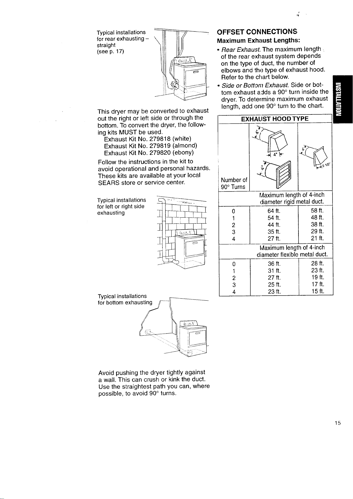
Typical installations
for rear exhausting -
straight
(see p. 17)
This dryer may be converted to exhaust
out the right or left side or through the
bottom. To convert the dryer, the follow-
ing kits MUST be used.
Exhaust Kit No. 279818 (white)
Exhaust Kit No. 279819 (almond)
Exhaust Kit No. 279820 (ebony)
Follow the instructions in the kit to
avoid operational and personal hazards.
These kits are available at your local
SEARS store or service center.
Typical installations
for left or right side
exhausting
'I
Typical installations
for bottom exhausting
OFFSET CONNECTIONS;
Maximum Exhaust Lengths:
, Rear Exhaust. The maximum length.
of the rear exhaust system depends
on the type of duct, the number of
elbows and the type of exhaust hood.
Refer to the chart below.
• Side or Botton7 Exhaust. Side or bot-
tom exhaust adds a 90 ° turn inside the
dryer. To determine maximum exhaust
length, add one 90 ° turn to the chart.
EXHALIST HOOD TYPE
Number of
90° Turns !
0
1
2
3
4
0
1
2
3
4
Maximum length of 4-inch
diameter rigid metal duct.
64 ft. 58 ft.
54 ft. 48 ft.
44 ft. 38 ft.
35 ft. 29 ft.
27 ft. 21 ft.
Ivlaximum length of 4-inch
diameter flexible metal duct.
36 ft. 28 ft.
31 ft. 23 ft.
27ft. 19ft.
25ft. 17ft.
23ft. 15ft.
Avoid pushing the dryer tightly against
a wall. This can crush or kink the duct.
Use the straightest path you can, where
possible, to avoid 90 ° turns.
15
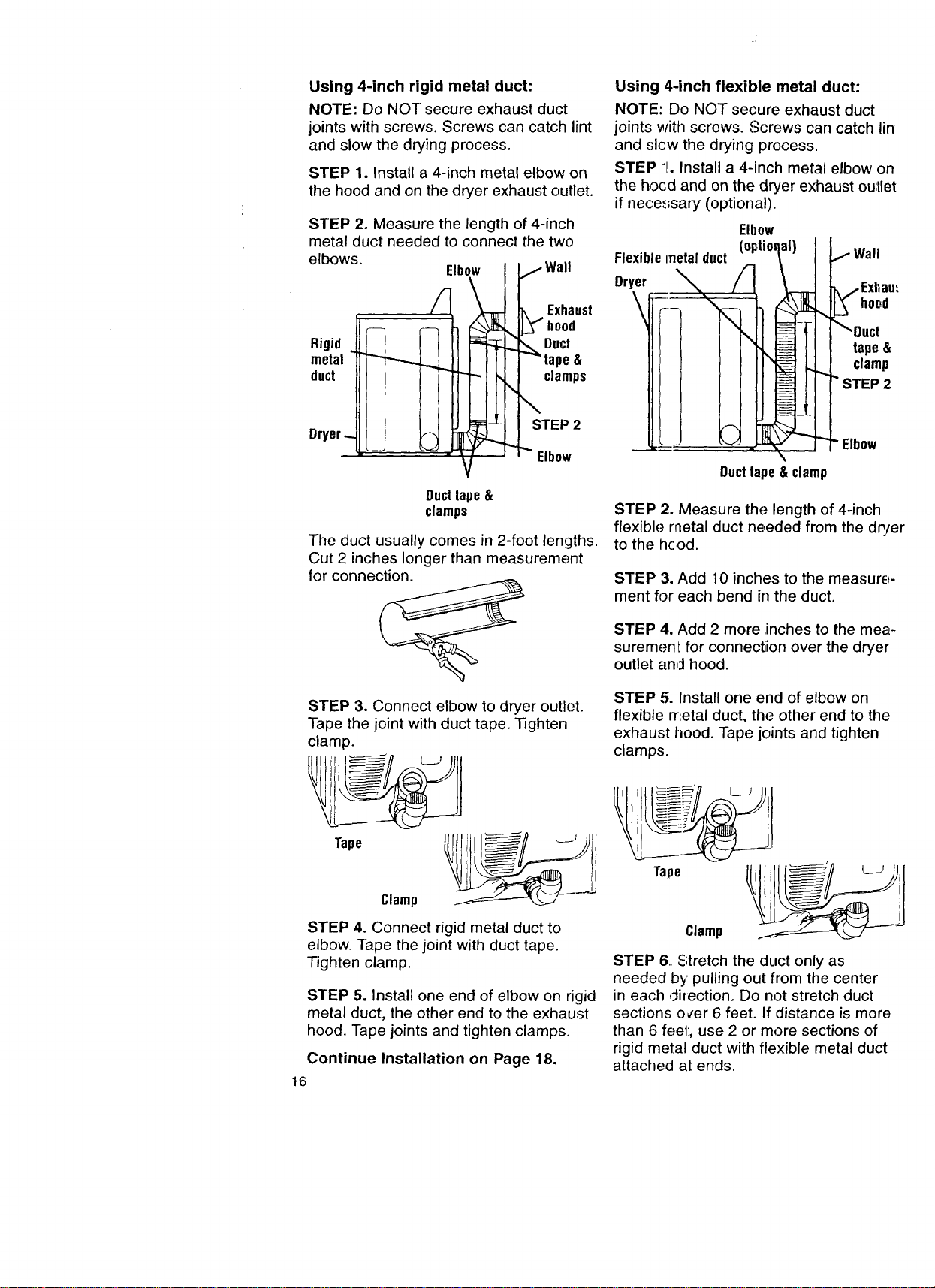
Using 4-inch rigid metal duct:
NOTE: Do NOT secure exhaust duct
joints with screws. Screws can catch lint
and slow the drying process.
STEP 1. Install a 4-inch metal elbow on
the hood and on the dryer exhaust outlet.
STEP 2. Measure the length of 4-inch
metal duct needed to connect the two
elbows.
Rigid
metal
duct
Dryer
Using 4-inch flexible metal duct:
NOTE: Do NOT secure exhaust duct
joints with screws. Screws can catch lin
and slcw the drying process.
STEP :J. Install a 4-inch metal elbow on
the hocd and on the dryer exhaust ou:tlet
if nece_<;sary (optional).
Ducttape&
clamps
The duct usually comes in 2-foot lengths.
Cut 2 inches longer than measurement
for connection.
STEP 3. Connect elbow to dryer outlet.
Tape the joint with duct tape. Tighten
clamp.
Clamp
Tape
STEP 4. Connect rigid metal duct to
elbow. Tape the joint with duct tape.
Tighten clamp.
STEP 5. Install one end of elbow on rigid
metal duct, the other end to the exhaust
hood. Tape joints and tighten clamps.
16
Continue Installation on Page 18.
Elbow
hood
tape&
clamp
STEP 2
Elbow
Ducttape& clamp
STEP 2. Measure the length of 4-inch
flexible metal duct needed from the dq/er
to the hcod.
STEP 3. Add 10 inches to the measure-
ment for each bend in the duct.
STEP 4. Add 2 more inches to the mea-
surement for connection over the dryer
outlet an,'l hood.
STEP 5. Install one end of elbow on
flexible metal duct, the other end to the
exhaust hood. Tape joints and tighten
clamps.
Tape
Clamp
STEP 6. Stretch the duct only as
needed by pulling out from the center
in each direction. Do not stretch duct
sections over 6 feet. If distance is more
than 6 feet, use 2 or more sections of
rigid metal duct with flexible metal duct
attached at ends.

FINISH INSTALLATION/
CHECKPOINTS
Taking a few minutes to complete
this checklist will help ensure a
proper installation and increase your
satisfaction with Kenmore dryers.
[] Check that all parts you removed
from the parts packages are now
installed.
[] Carefully slide dryer into its final
location.
[] Check to be sure dryer is level
by placing level on top of the dryer,
first side-to-side then front-to-back.
If dryer is not level, adjust the legs
up or down.
[] Check to make sure you have all
the tools you started with.
[] Plug the power supply cord into the
grounded outlet or connect direct
wire to power supply. Turn power
supply on.
[] Wipe the interior of the drum
thoroughly with a damp cloth to
remove any dust.
[] Read the rest of this manual to fully
understand your new dryer. Start the
dryer and allow it to complete a full
heat cycle (not the air cycle). You
may notice a burning odor. This smell
is common when the heating element
is first used. The smell will go away.
After five minutes, open dryer door.
You should feel heat inside the dryer.
If you do not feel heat, see Trouble-
shooting information on pages 35-36.
18
STARTING YOUR DRYER
Explosion Hazard
Never place items in the dryer that
are dampened with gasoline or other
flammable fluids.
Do not wash or dry items soiled with
vegetable or cooking oils because
they may contain some oil after
laundering.
Doing so can result in death,
explosion, or fire.
To get the best drying results, you must
operate your dryer properly. This section
gives you this important information.
Page references are included for more
information. You can also refer to the
"Feature Sheet" supplied with your dryer.
STEP 1. Check lint screen. Clean
if needed.
STEP 2. Put laundry into dryer and
shut door.
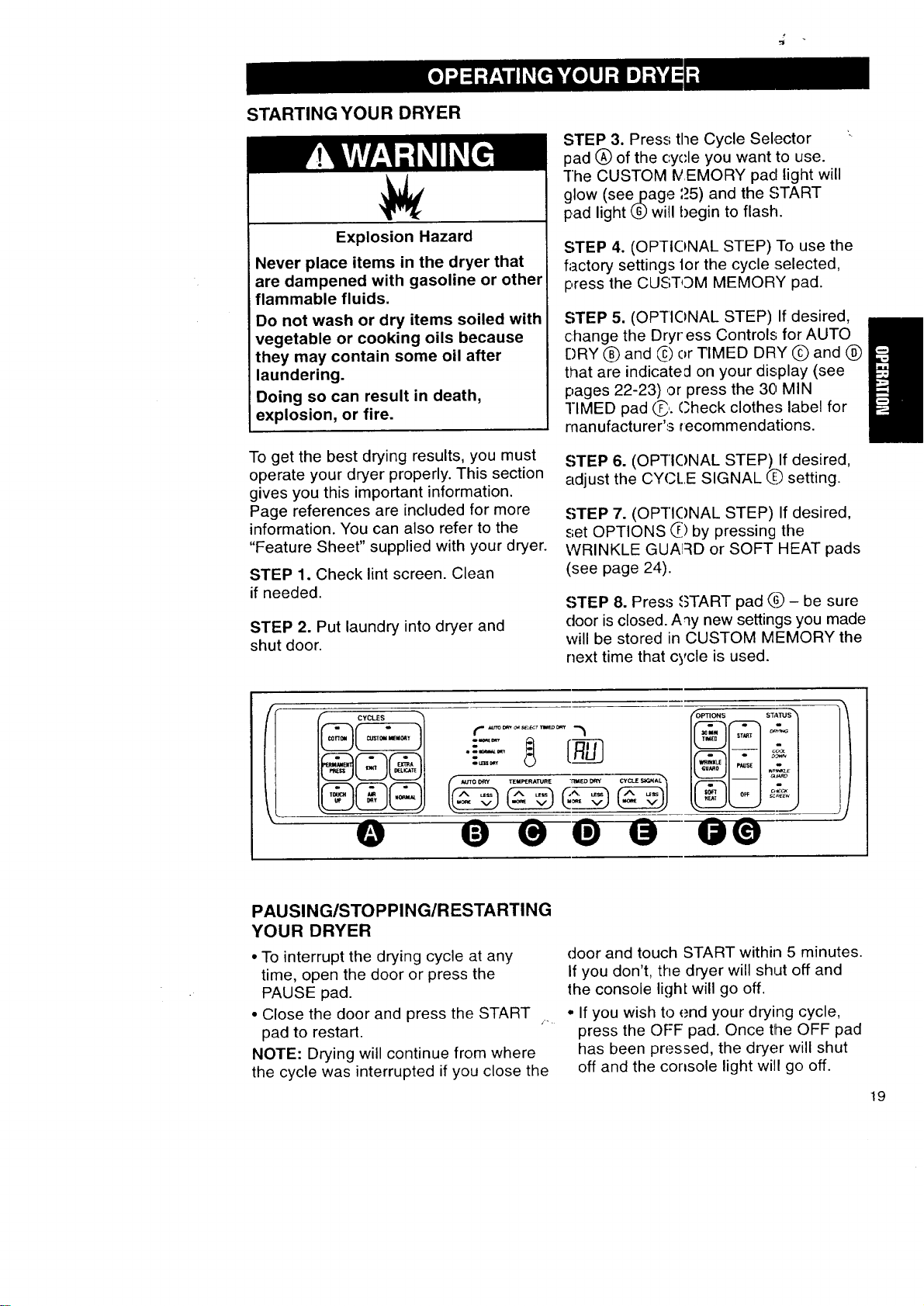
STEP 3. Press the Cycle Selector
pad (_) of the cycle you want to use.
The CUSTOM IVEMORY pad light will
,)
glow (seepage ,.5) and the START
pad light L_)will begin to flash.
STEP 4. (OPTIONAL STEP) To use the
factory settings 1orthe cycle selected,
press the CUSTOM MEMORY pad.
STEP 5. (OP-I"IONAL STEP) If desired,
change the Dryr"ess Controls for AUTO
DRY (_ and _) or TIMED DRY (_ and @
that are indicated on your display (see
pages 22-23),or press the 30 MIN
rIMED pad C'- Check clothes label for
manufacturer's recommendations.
STEP 6. (OPf]C)NAL STEP) If desired,
adjust the CY(.,t..E SIGNAL Q setting.
STEP 7. (OP'I"IONAL STEP) If desired,
set OPTIONS 0 by pressing the
WRINKLE GUA!:_D or SOFT HEAT pads
(see page 24).
STEP 8. Press ,_TART pad _ - be sure
door is closed. Aqy new settings you made
will be stored in CUSTOM MEMORY the
next time that cycle is used.
O
coot
Dow_
PAUSING/STOPPING/RESTARTING
YOUR DRYER
• To interrupt the drying cycle at any
time, open the door or press the
PAUSE pad.
• Close the door and press the START
pad to restart.
NOTE: Drying will continue from where
the cycle was interrupted if you close the
door and touch START within 5 minutes.
If you don't, the dryer will shut off and
the console ligh[ will go off.
• If you wish to end your drying cycle,
press the OFF pad. Once tlhe OFF pad
has been pressed, the dryer will shut
off and the console light will go off.
19
Your dryer can be operated using
one of two methods. One way is to
use the preset memory settings that
were programmed for your dryer
at the factory. This page describes
your dryer's cycles and the preset
memory settings.
You can also use CUSTOM MEMORY
to modify the recommended factory
settings to fit your drying needs. For
a detailed description on how to use
CUSTOM MEMORY, see page 25.
CYCLE DESCRIPTION
(Cycle Selection Pads)
When one of the Cycle Selection pads
is pressed, the console light comes on
and the START light flashes on and off.
A drying heat range is automatically set
for the type of fabric selected.
f CYCLES
I;US'[OM MEMOKY
COTTON
Use this cycle to get a high range of
heat for heavy fabrics.
PERMANENT PRESS
Use this cycle to get a medium range
of heat for synthetic fabrics and no-ir_.'
finishe.';.
KNIT
Use this cycle to get a medium low
range of heat for washable knit fabric,'
EXTRA DELICATE
Use thi,,; cycle to get a low range of
heat for drying heat-sensitive fabrics.
NORMAL
Use thi.,; cycle to get a medium high
range of heat for sturdy fabrics.
TOUCH UP
Use thi_ cycle to get a medium range
of heat 1o smooth synthetic and perma
nent press clothes that are clean but
wrinklee from being crowded in a clos,_
or suitcase.
• These settings have been preset for
optimum fabric care and are not
adjustable.
• Cycle provides about 30 minutes of
drying l:ime - 20 minutes of tumbling
with medium heat followed by a 10-
minute (approx.) COOL DOWN perio,:
• Remove clothes immediately when
tumbling stops.
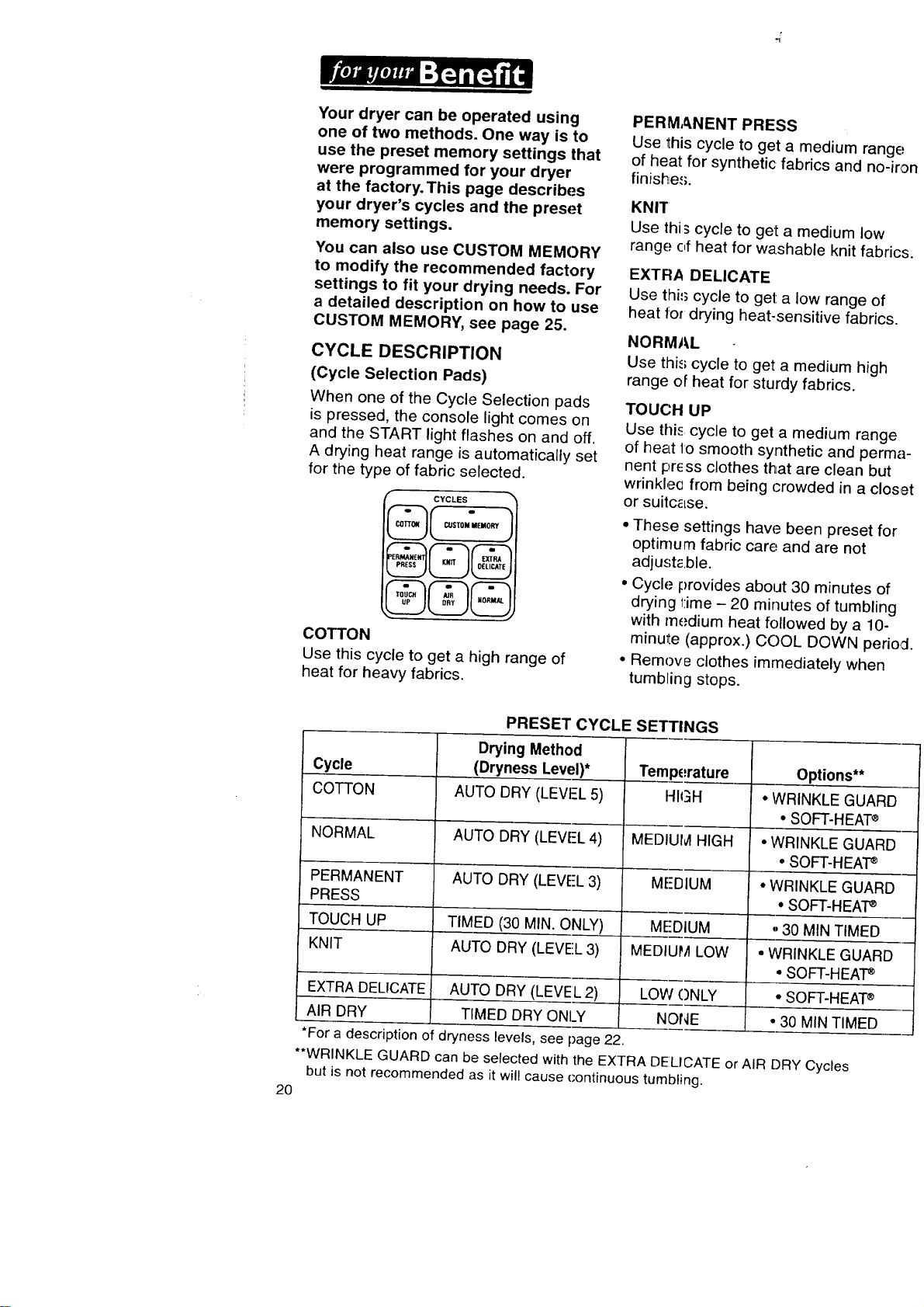
PRESET CYCLE SETTINGS
Drying Method
Cycle (Dryness Level)* Tern )erature Options**
COTTON AUTO DRY (LEVEL 5) HIGH • WRINKLE GUARD
• SOFT-HEAT®
NORMAL AUTO DRY (LEVEL 4) MEDI HIGH • WRINKLE GUARD
• SOFT-HEAP
PERMANENT AUTO DRY (LEVE-L3) MFDIUM • WRINKLE GUARD
PRESS • SOFT-HEAP
TOUCH UP TIMED (30 MIN. ONLY) MEDIUM _ 30 MIN TIMED
KNIT AUTO DRY (LEVEL 3) MED, LOW • WRINKLE GUARD
• SOFT-HEAT_
EXTRA DELICATE AUTO DRY (LEVEL 2) LOW ONLY • SOFT-HEAT®
AIR DRY TIMED DRY ONLY NONE • 30 MIN TIMED
*For a description of dryness levels, see page 22.
**WRINKLE GUARD can be selected with the EXTRA DELICATE or AIR DRY Cycles
but is not recommended as it will cause continuous tumbling.
20
USING AIR DRY
Using this cycle gives you all the
benefits of hang drying with a shorter
drying time.
Use the AIR DRY Cycle for items that
will not tolerate heat such as plastics
and foam rubber. Also use for airing and
fluffing items such as pillows.
• The AIR DRY Cycle is preset for
30 minutes but can be adjusted from
1 to 99 minutes any time during the
cycle.
• An AUTO DRY selection cannot be
made when using the AIR DRY Cycle.
Pressing the MORE or LESS pads
under AUTO DRY will result in three
short tones which indicate an unavail-
able option was selected.
NORMAL
Fire Hazard
Use AIR DRY Cycle to dry items
listed below.
Do not use heat to dry these items.
Failure to do so can result in death
or fire.
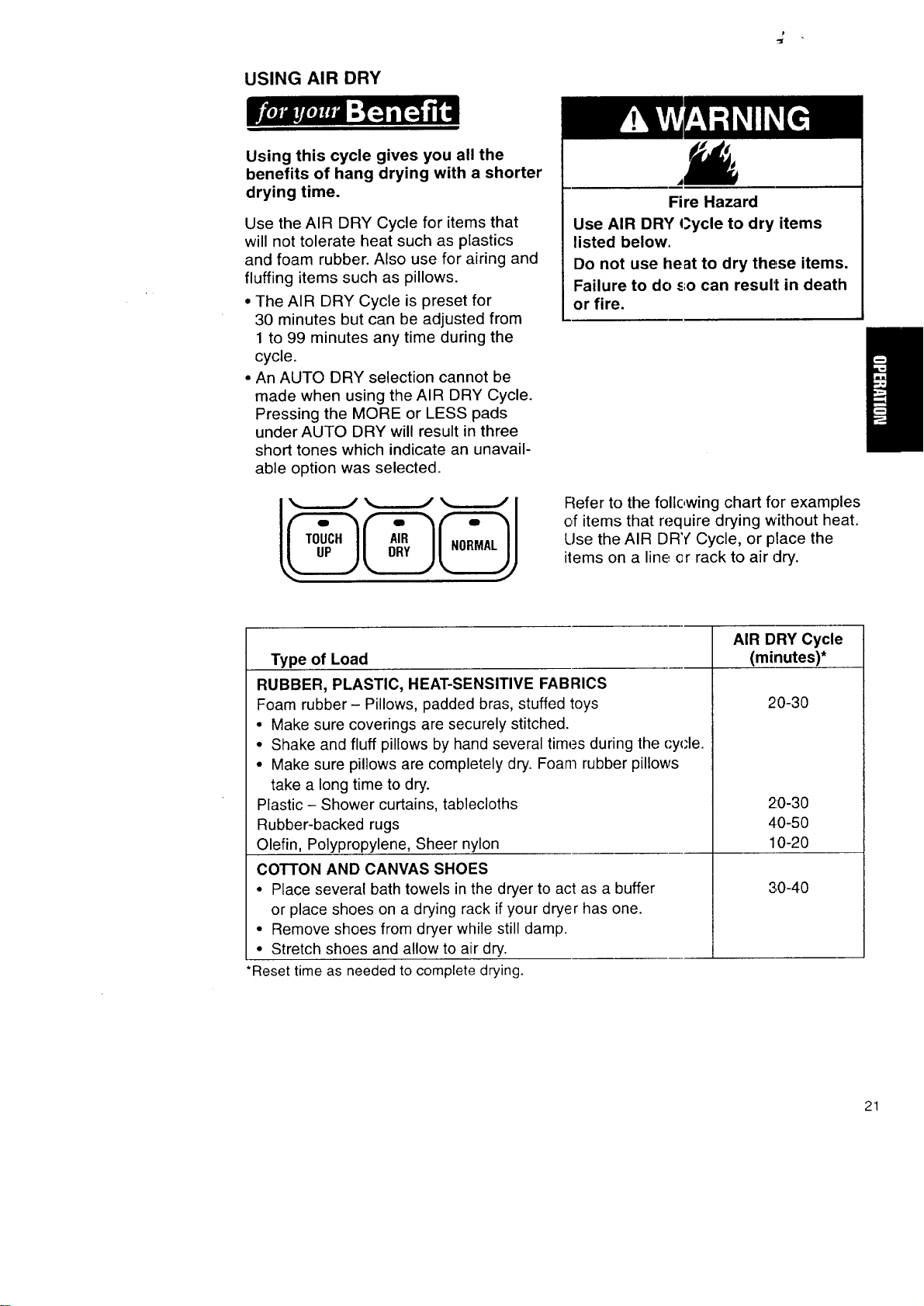
Refer to the following chart for examples
of items that require drying without heat.
Use the AIR DRY Cycle, or place the
items on a line, or rack to air dry.
Type of Load
RUBBER, PLASTIC, HEAT-SENSITIVE FABRICS
Foam rubber- Pillows, padded bras, stuffed toys
° Make sure coverings are securely stitched.
• Shake and fluff pillows by hand several times during the cyc-le.
• Make sure pillows are completely dry. Foam rubber pillows
take a long time to dry.
Plastic - Shower curtains, tablecloths
Rubber-backed rugs
Olefin, Polypropylene, Sheer nylon
COTTON AND CANVAS SHOES
• Place several bath towels in the dryer to act as a buffer
or place shoes on a drying rack if your dryer has one.
• Remove shoes from dryer while still damp.
• Stretch shoes and allow to air dry.
•Reset time as needed to complete drying.
AIR DRY Cycle
(minutes)*
2:0-30
2:0-30
4.0-50
10-20
30-40
21
DRYNESS CONTROLS
AUTO DRY
AUTO DRY saves you time by
providing the best drying results
in the shortest time. This can help
you save money on utility bills and
reduce the risk of fabric damage,
Use this cycle for most loads. Drying time
varies according to type of fabric, size of
load and dryness setting.
• Set the Dryness Control to
NORMAL DRY(*) which is good
for most fabrics.
• Display will show "AU" until the last
few minutes of the cycle when it will
change to show the number of minutes
remaining.
• At the end of the cycle, feel the dried
clothes. If they are damp, select MORE
DRY the next time you do a similar load.
If they are overdried, select LESS DRY
the next time you do a similar load.
• Dryness is determined by an electronic
sensor that "feels" the amount of mois-
ture in clothes as they pass over it. When
the dryness selected is reached, the dryer
goes into a COOL DOWN period. The
amount of COOL DOWN time depends
on load size and dryness setting.
• The CYCLE SIGNAL sounds once the
cycle is completed.
• If you do not unload the dryer, it goes
into WRINKLE GUARD, if selected. For
an explanation of WRINKLE GUARD,
see page 24.
22
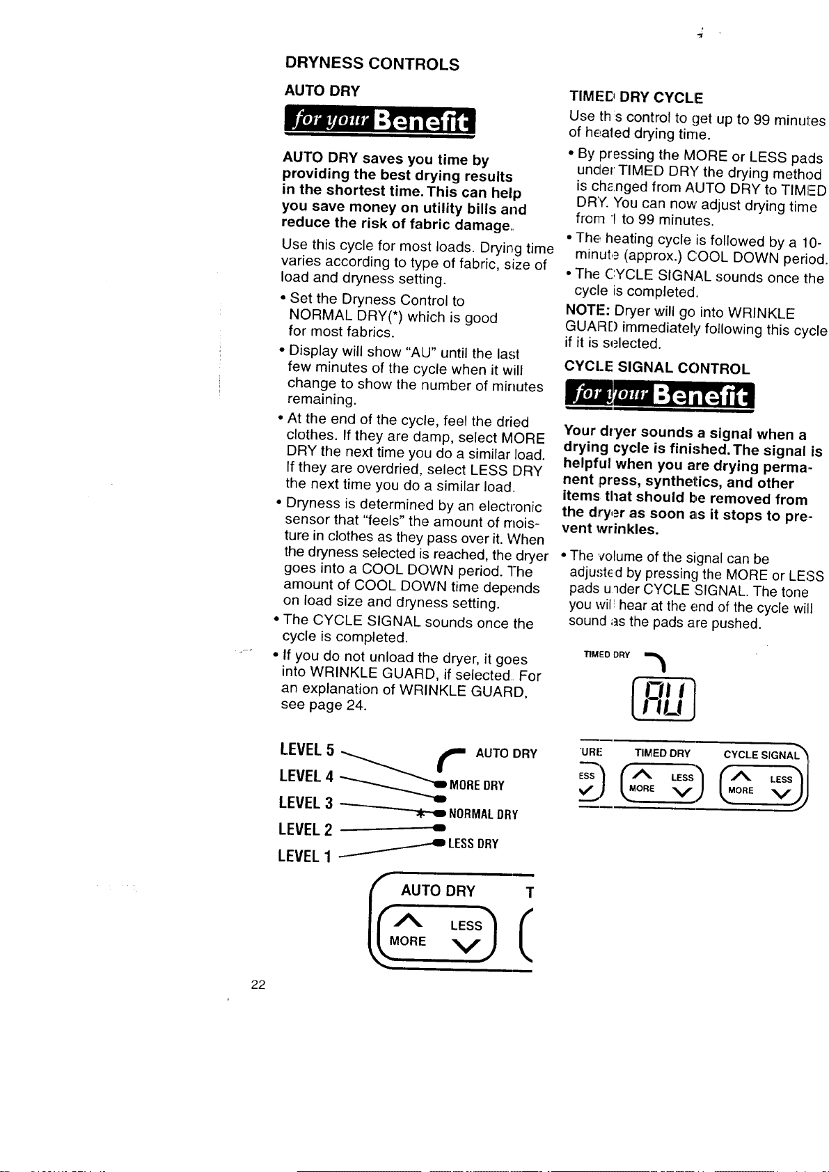
LEVEL 5 -__ _ AUTO DRY
LEVEL 4 _ MOREDRY
LEVEL 3 -_ NORMALDRY
LEVEL 2 -
LESSDRY
LEVEL 1
_RREAUTODRY T
TIMED DRY CYCLE
Use ths control to get up to 99 minute,'
of healed drying time.
• By pressing the MORE or LESS pads
under TIMED DRY the drying method
is chenged from AUTO DRY to TIMI--E
DR"(. You can now' adjust drying time
from 1 to 99 minutes.
• The, heating cycle is followed by a 10-
minut,_ (approx.) COOL DOWN perioc
• The CYCLE SIGNAL sounds once the
cycle is completed.
NOTE: Dryer will go into WRINKLE
GUARD immediately following this cycl_
if it is selected.
CYCLE SIGNAL CONTROL
Your dryer sounds a signal when a
drying cycle is finished.The signal is
helpful when you are drying perma-
nent press, synthetics, and other
items tl_at should be removed from
the dryer as soon as it stops to pre-
vent wrinkles.
• The volume of the signal can be
adjusted by pressing the MORE or LESS
pads u_der CYCLE :SIGNAL. The tone
you wil! hear at the end of the cycle will
sound as the pads are pushed.
TIMED DRY
"URE TIMED DRY CYCLE SIGNAL _=
-- /
ORE
TEMPERATURE CONTROL
Proper use of this control helps
ensure that fabrics are dried in
the right temperature range for
maximum life.
Use this control to select the tempera-
ture range for the cycle you are using.
• The MORE or LESS pads under the
TEMPERATURE selection allow you to
choose one of five different tempera-
tures. See chart (right) for settings and
display.
• The TEMPERATURE Control
will not work with TOUCH UP or AIR
DRY Cycles.
COOL DOWN
Approximately ten minutes before the
end of a heated drying cycle, clothes are
tumbled without heat to help reduce
wrinkles and make clothes more com-
fortable to handle.
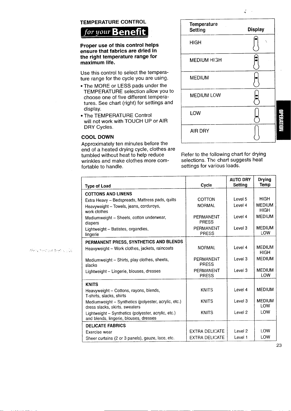
Temperature
Setting Display
HIGH _)
MEDIUM HISH _)
MEDIUM (_)
MEDIUM LOW (_
LOW _)
AIR DRY (_)
Refer to the following chart for drying
selections. The, chart suggests heat
settings for various loads.
Type of Load
COTTONS AND LINENS
Extra Heavy - Bedspreads, Mattress pads, quilts
Heavyweight- Towels, jeans, corduroys,
work clothes
Mediumweight - Sheets, cotton underwear,
diapers
Lightweight - Batistes, organdies,
lingerie
PERMANENT PRESS, SYNTHETICS AND BLENDS
Heavyweight - Work clothes, jackets, raincoats
Mediumweight - Shirts, play clothes, sheets,
slacks
Lightweight- Lingerie, blouses, dresses
KNITS
Heavyweight - Cottons, rayons, blends,
T-shirts, slacks, shirts
Mediumweight - Synthetics (polyester, acrylic, etc.)
dress slacks, skirts, sweaters
Lightweight - Synthetics (polyester, acrylic, etc.)
and blends, lingerie, blouses, dresses
DELICATE FABRICS
Exercise wear
Sheer curtains (2 or 3 panels), gauze, lace, etc.
Drying
Cycle Temp
CO-I-I-ON
NORMAL
PERMANENT
PRESS
PERMANENT
PRESS
NORMAL
PERMANENT
PRESS
PERMANENT
PRESS
KNITS
KNITS
KNITS
EXTRA DELICATE
EXTRA DELICATE
AUTO DRY
Setting
Level 5
Level 4
Level 4
Level 3
Level 4
Level 3
Level 3
Level 4
Level 3
Level 2
Level 2
Level 1
HIGH
MEDIUM
HIGH
MEDIUM
MEDIUM
LOW
MEDIUM
HIGH
MEDIUM
MEDIUM
LOW
MEDIUM
MEDIUM
LOW
LOW
LOW
LOW
23
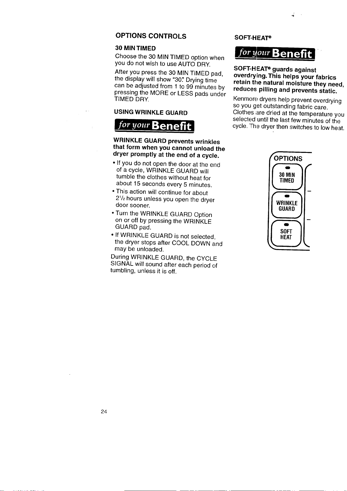
OPTIONS CONTROLS
30 MIN TIMED
Choose the 30 MIN TIMED option when
you do not wish to use AUTO DRY.
After you press the 30 MIN TIMED pad,
the display will show "30; Drying time
can be adjusted from 1 to 99 minutes by
pressing the MORE or LESS pads under
TIMED DRY.
USING WRINKLE GUARD
WRINKLE GUARD prevents wrinkles
that form when you cannot unload the
dryer promptly at the end of a cycle.
• If you do not open the door at the end
of a cycle, WRINKLE GUARD will
tumble the clothes without heat for
about 15 seconds every 5 minutes.
• This action will continue for about
21/2hours unless you open the dryer
door sooner.
• Turn the WRINKLE GUARD Option
on or off by pressing the WRINKLE
GUARD pad.
• If WRINKLE GUARD is not selected,
the dryer stops after COOL DOWN and
may be unloaded.
During WRINKLE GUARD, the CYCLE
SIGNAL will sound after each period of
tumbling, unless it is off.
SOFT-HEAT _
SOFT.H EATe guards against
overdrying. This helps your fabrics
retain the natural moisture they nee!
reduces pilling and prevents static.
Kenmore dryers help prevent overdryinc
so you get outstanding fabric care.
Clothes ;_re dried at tlhe temperature yc
selected until the last few minutes of the.=
cycle. "l-he dryer then switches to low he;.-"
fOPTIONS
I_
24
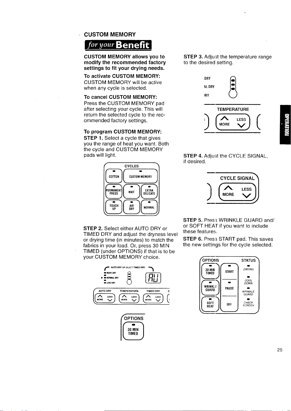
CUSTOM MEMORY
CUSTOM MEMORY allows you to
modify the recommended factory
settings to fit your drying needs.
To activate CUSTOM MEMORY:
CUSTOM MEMORY will be active
when any cycle is selected.
To cancel CUSTOM MEMORY:
Press the CUSTOM MEMORY pad
after selecting your cycle. This will
return the selected cycle to the rec-
ommended factory settings.
To program CUSTOM MEMORY:
STEP 1. Select a cycle that gives
you the range of heat you want. Both
the cycle and CUSTOM MEMORY
pads will light.
r CYCLES _'
CUSTOM MEMORY
@@@
STEP 2. Select either AUTO DRY or
TIMED DRY and adjust the dryness level
or drying time (in minutes) to match the
fabrics in your load. Or, press 30 MIN
TIMED (under OPTIONS) if that is to be
your CUSTOM MEMORY choice.
l AUTOORY ORSELECTTIMEDDRY
_ _ NORMALDAy
_I.[_'$ DRY
I_ TEMPERATURE TIMED DRY C
(OPTIONS
STEP 3. Adjust the temperature range
to the desired setting.
_,LDRY
IRY
TEMPERATURE
STEP 4. Adjust the CYCLE- SIGNAL,
if desired.
CYCLE SIGNA h
] CA L sql
__L°o. v J)
STEP 5. Press WRINKLE GUARD and/
or SOFT HE!AT if you want to include
these feature.,;.
STEP 6. Press START pad. This saves
the new settings for the cycle selected.
/OPT_Ot|S STATUS "_
DRYING
I TIMED/
_ -- ' _OL
I I DOWN
I WRINKLE I ,
PAUSE
IB
I GUARD I
!
WRINKLE
_--_ GUARD
j.._=.___ -- m
C_ECK
i S(]Fr m OFF I SCREEN
HEAT I
25
OPERATING CONTROLS
START
Use this control to start the dryer,
Be sure the dryer door is closed.
Opening the door stops the dryer. It will
not start again until you close the door
and press the START pad.
NOTE: If you do not close the dryer door
and press the START pad within 5 minutes
of when the dryer door was opened, the
dryer will shut off. You will have to select
a new cycle to restart the dryer.
PAUSE
Use this control to temporarily stop the
dryer cycle.
• If PAUSE is pressed and you open
the dryer door, you must close the door
and press the START pad to restart
the dryer (see NOTE above).
• If PAUSE is pressed and you leave
the dryer door closed, you can return
to the dryer and press the START pad.
The dryer will continue at the point it
left off in the cycle.
NOTE: There is no time limit on PAUSE,
if you do not open the dryer door.
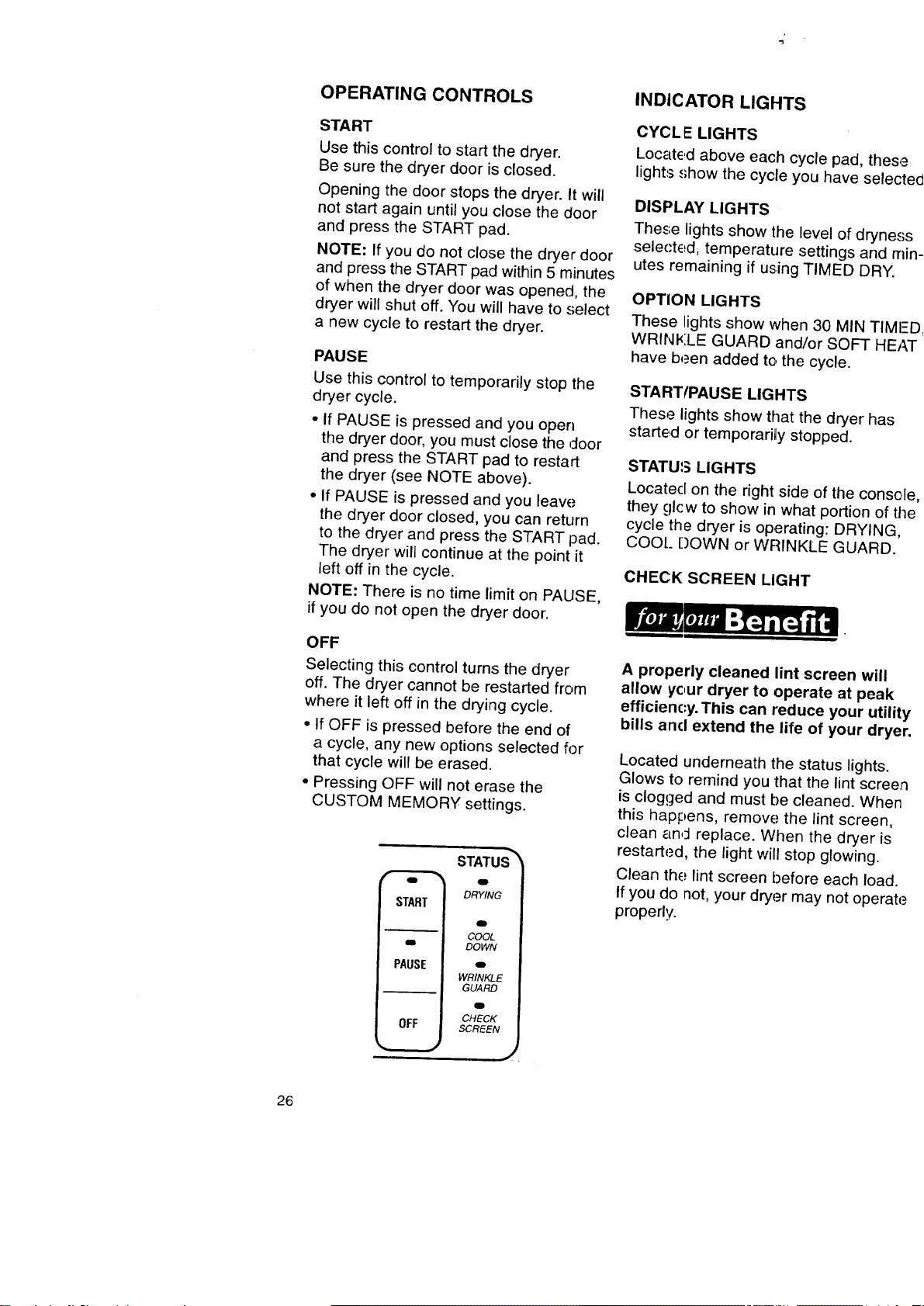
OFF
Selecting this control turns the dryer
off. The dryer cannot be restarted from
where it left off in the drying cycle.
• If OFF is pressed before the end of
a cycle, any new options selected for
that cycle will be erased.
• Pressing OFF will not erase the
CUSTOM MEMORY settings.
STATUSTM
DRYING
START
o
-- COOL
e DOWN
PAUSE o
WRINKLE
GUARD
CHECK
OFF SCREEN
i
J
INDICATOR LIGHTS
CYCLE LIGHTS
Located above each cycle pad, thes
lights show the cycle you have selec
DISPLAY LIGHTS
These lights show the level of dryne:
selected, temperature settings and r
utes remaining if using TIMED DRY.
OPTION LIGHTS
These Lights show when 30 MIN TIM
WRINKLE GUARD and/or SOFT HE
have been added to the cycle.
STARTfPAUSE LIGHTS
These lights show that the dryer has
started or temporarily stopped.
STATU_, LIGHTS
Located on the right side of the consc
they glcw to show in what portion of tJ
cycle the dryer is operating: DRYING,
COO!.. [)OWN or WRINKLE GUARD.
CHECK SCREEN LIGHT
A properly cleaned lint screen will
allow yc,ur dryer to operate at peak
efficienc:y. This can reduce your utili'
bills ancl extend the life of your dry(
Located underneath the status lights.
Glows to remind you that the lint scree
is clogged and must be cleaned. Wher
this happens, remove the lint screen,
clean and replace. When the dryer is
restarted, the light will stop glowing.
Clean the lint screen before each load.
If you do not, your dryer may not operat
properly.
26
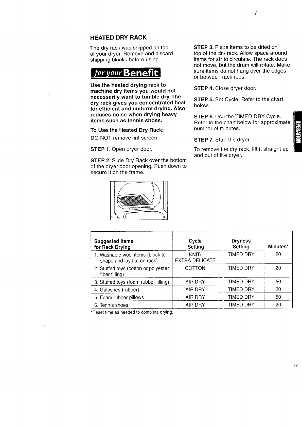
HEATED DRY RACK
The dry rack was shipped on top
of your dryer. Remove and discard
shipping blocks before using.
Use the heated drying rack to
machine dry items you would not
necessarily want to tumble dry.The
dry rack gives you concentrated heat
for efficient and uniform drying. Also
reduces noise when drying heavy
items such as tennis shoes.
To Use the Heated Dry Rack:
DO NOT remove lint screen.
STEP 1. Open dryer door.
STEP 2. Slide Dry Rack over the bottom
of the dryer door opening. Push down to
secure it on the frame.
STEP 3. Place items to be dried on
top of the ,dr/rack. Allow space around
items for air to circulate. The rack does
not move, but the drum will rotate. Make
sure items do not hang over the edges
or between rack rods.
STEP 4. Close dryer door.
STEP 5. Set Cycle. Refer to the chart
below.
STEP 6. Use the TIMED DRY Cycle.
Refer to the chart below '[or approximate
number of minutes.
STEP 7. Start the dryer.
To remove the dry rack, lift it straight up
and out of the dryer.
Suggested Items
for Rack Drying
1. Washable wool items (block to
,
shape and lay flat on rack)
Stuffed toys (cotton or polyester
fiber filling)
3. Stuffed toys (foam rubber filling)
4. Galoshes (rubber)
5. Foam rubber pillows
6. Tennis shoes
*Resettimeasneededto completedrying.
Cycle
Setting
KNIT/
EXTRA DELICATE
Dryness
Setting
TIMED DRY
Minutes*
2O
COTTON TIMED DRY 20
AIR DRY TIMED DRY
AIR DRY TIMED DRY
AIR DRY TIMED DRY
AIR DRY TIMED DRY
5O
20
5O
2O
27
Following these recommendations
will help you save on utility bills and
prolong the life of your garments.
This section provides information on pre-
paring clothes for drying and instructions
for drying special-care items.
• Refer to your Washer Owner's Manual
for proper washing techniques and
additional laundry tips.
• See page 3 of this book for Important
Safety Instructions.
SORTING CLOTHES
• Separate dark from light colors;
colorfast from non-colorfast. Items
properly sorted by color for washing
are usually properly sorted for drying.
• Separate heavy fabrics (denim,
towels) from light fabrics (synthetics,
permanent press).
• Separate lint givers (towels, chenille)
from lint takers (corduroy, synthetics,
permanent press). When possible,
turn lint takers inside out.
CHOOSING LOAD SIZES
• Mix large items with smaller items.
Load the dryer by the amount of space
items take up, not by their weight, r)o
not overload the dryer. Overcrowding
causes uneven drying and wrinkling,
and can cause items to wear out faster
(because of pilling).
You may need to rearrange large items
(sheet.r, blankets, tablecloths) during
a cycle to reduce bailing or rolling up.
For better tumbling action, when
drying only a few small items, add
one or two lint-free towels. This also
prever:ts small lightweight items from
blocking airflow.
SUPER CAPACITY PLUS DRYERS
Heavy Work
Clothes
4 jean.,;
4 workpants
4 workshirts
2 sweatshirts
2 swe_Ltp_Lnts
Towels
10 bath towels
10 hand towels
14 wash cloths
Mixed Load
3 sheets
(1 king, 2 twin)
4 pillowcases
3 shirts
3 blouses
9 T-shirts
9 shorts
10 handkerchiefs
DRYING TIPS
• Close zippers, snaps and hooks to
avoid snagging other items. Remove
heat-sensitive trim that can be dama£/ed
by drying. Tie strings and sashes so
they will not tangle.
• Check garments for spots and stains
left after washing, r)o not tumble these
item.,;. Heat may permanently set stains.
• Sharp 3r metal objects can damage
your dryer. Check pockets before drying.
Do not lay these objects on your dryer.
Turn pockets of heavy items inside out
for even drying.
• Place small items such as baby socks
or hankies in laundry bag for easier
removal.
• Articles to be ironed should be
removed while still damp.
T,J-L_
28
USING DRYER
FABRIC SOFTENERS
Dryer fabric softeners are recommended
for reducing static cling. Always follow
package instructions carefully.
• Put one fabric softener sheet on top
of the load before starting the dryer.
Do not add a fabric softener sheet after
the drying cycle has started. Instant
heat can cause the fabric softener to
spot fabrics.
• Remove fabric softener stains by wet-
ting the stains and rubbing them with
liquid detergent or bar soap and rewash.
• Some fabric softeners can clog the
lint screen and slow drying. Use fabric
softeners labeled as dryer safe.
SAVING ENERGY
• Use the AUTO DRY Cycle to dry
most loads.
• Dry full loads only. Do not overdry.
• Avoid overloading dryer, adding wet
items to a partly dried load, or opening
the door unnecessarily.
• Shorten drying times by exhausting
dryer properly and cleaning exhaust
duct and outside exhaust hood as
needed.
- Keep the lint screen clean.
- Use dryer where room air tempera-
ture is above 45°F.
- Sort loads by fabric weight and type.
DRYING SPECIAL-CARE ITEMS
Most garmerTts and household textiles
have manufacturer's care labels with
laundering instructions. Always follow
care label directions when they are
available. Pages 29 and 30 include
drying instructions for most types of
washables.
Blankets and woolens
Machine drying knitted woolens is not
recommended. Block to shape when
wet and allow to air dry. Line dry blankets
in the shade on a breezy day over two
lines. Pin edges together and straighten
them. When partly dry, turn the blanket
over, re-pin, and re-straighten. When dry,
brush nap.
Cotton, rayon synthetic blankets
Dry as recommended for permanent
press fabrics on page 23.
Electric blankets, electric sheets, woolen
blankets, washable woolen garments
If manufacturer recommends machine
drying:
1. Place one or two dry towels in the
dryer and preheat 3-5 minutes on
a high set':ing. This will dry blankets
faster and help avoid pilling.
2. Put blanket in dryer with warm towels.
Set control for 20 minutes.
3. Check after 10 minutes. Remove
when still damp. Overdrying and
long tumbling can cause shrinking
and pilling.
4. Place blanket on flat surface, or
over two lines to finish drying. Gently
stretch to original size and shape.
5. When completely dry, brush gently
to raise nap. Press binding with cool
iron if needed.
29
Curtains, slipcovers
Remove drapery weights and hooks
before laundering.
For slipcovers, replace while still slightly
damp. They will dry to fit tightly.
Draperies, slipcovers
Dry only a few minutes.
1. Leave room in dryer for load to fluff.
2. Remove from dryer while slightly
damp. Do not overdry.
Diapers, baby clothes
Wash and dry small items in a mesh bag
or pillowcase for convenient handling.
Remove diapers and cotton knit items
while still slightly damp. They will feel
softer, shrink less and be easier to fold.
Elastic items
Remove from dryer while still slightly
damp.
Flame-retardant finishes
Some items have been treated with a
flame-retardant finish to improve their
resistance to burning. Such items are
clearly labeled. To retain flame-retardant
qualities through continuous use and
washing, clean and dry according to the
care label instructions.
Napped items
Dry separately or with similar colors
to avoid lint transfer. Follow care label
instructions.
Corduroy, velveteen
1. Remove from dryer while they are
slightly damp.
2. Smooth, reshape, and air dry before
putting away.
Quilted, down-filled items
Follow care label instructions.
1. Dry one at a time.
2. Remove from dryer and shake or fluff
the item during the, drying cycle.
3. Smooth and reshape before putting
away.
Snowsuits, jackets
Check label for fiber content, then follow
care label instructions.
Nylon or polyester
1. Dry garment for about 10 minutes.
Remove and turn inside out. Dry for
10 more minutes.
2. Remove from dryer immediately and
hang on a non-rusting hanger to finish
drying This will help eliminate
wrinkles.
Tinted, C!yed, or non-colorfast items
Dry according to fabric, weight and care
label instructions. Wipe the dryer drum
carefully to remove any dye or lint. See
"Cleaning Your Dryer" on page 31.
Washable knits
Do not overdry knits. Overdrying
can cause shrinking and static cling.
1. Select cycle according to fabric
construction.
2. Turn synthetics and blends inside
out when drying to avoid pilling.
3. Remove cottons and rayon knits
while s'.ill slightly damp. Stretch into
shape and lay flat to finish drying.
3O
This section explains how to care for
your dryer properly and safely.
Proper care of your dryer can extend
its life and help you avoid costly
service calls.
EXTERIOR
Use a soft, damp cloth to clean the
cabinet. Avoid using harsh abrasives.
Do not put sharp metal objects on or in
your dryer. They can damage the finish.
INTERIOR
Explosion Hazard
Use nonflammable cleaners.
Failure to do so can result in death,
explosion, fire, or burns.
CLEANING YOUR DRYER
Garments that contain unstable dyes,
such as denim blue jeans or brightly
colored cotton items, may discolor the
drum interior.
To clean dryer drum:
STEP 1. Make a paste with detergent
and very warm water and apply to a soft
cloth. Continue with STEPS 2-4.
or
STEP la. Spray non-flammable liquid
household cleaner on the stained area.
Continue with STEPS 2-4.
STEP 2. Scrub area until all excess
dye is remow;d.
STEP 3. Wipe thoroughly with a
damp cloth,
STEP 4. Tuml31e a load of clean towels
for 20 minutes to dry.
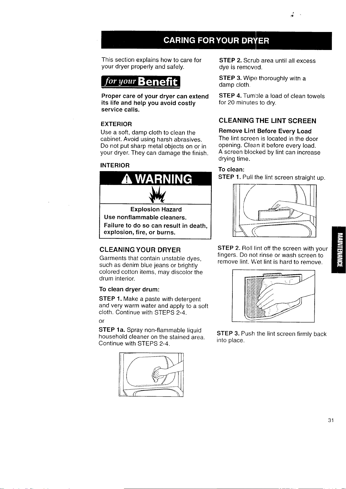
CLEANING THE LINT SCREEN
Remove Lint Before Every Load
The lint screen is located in the door
opening. Clean it before every load.
A screen blocked by lint can increase
drying time.
To clean:
STEP 1. Pull lhe lint screen straight up.
i
STEP 2. Roll lint off the screen with your
fingers. Do not rinse or wash screen to
remove lint. Wet lint is hard to remove.
STEP 3. Push the lint screen firmly back
into place.
31
IMPORTANT:
• Do not run the dryer with the lint screen
loose, damaged, blocked, or missing.
Doing so can cause overheating and
damage to both the dryer and fabrics.
• Some towels made of synthetic fibers
and natural fibers (polyester and cotton
blends) may shed more lint than other
towels, causing your dryer's lint screen
to fill up faster. Be sure to remove lint
from the lint screen before and after
drying new towels.
Clean Lint Screen As Needed
Laundry detergents and fabric softeners
can cause a residue buildup on the lint
screen. Clean the lint screen with a nylon
brush if it becomes clogged due to a
residue buildup.
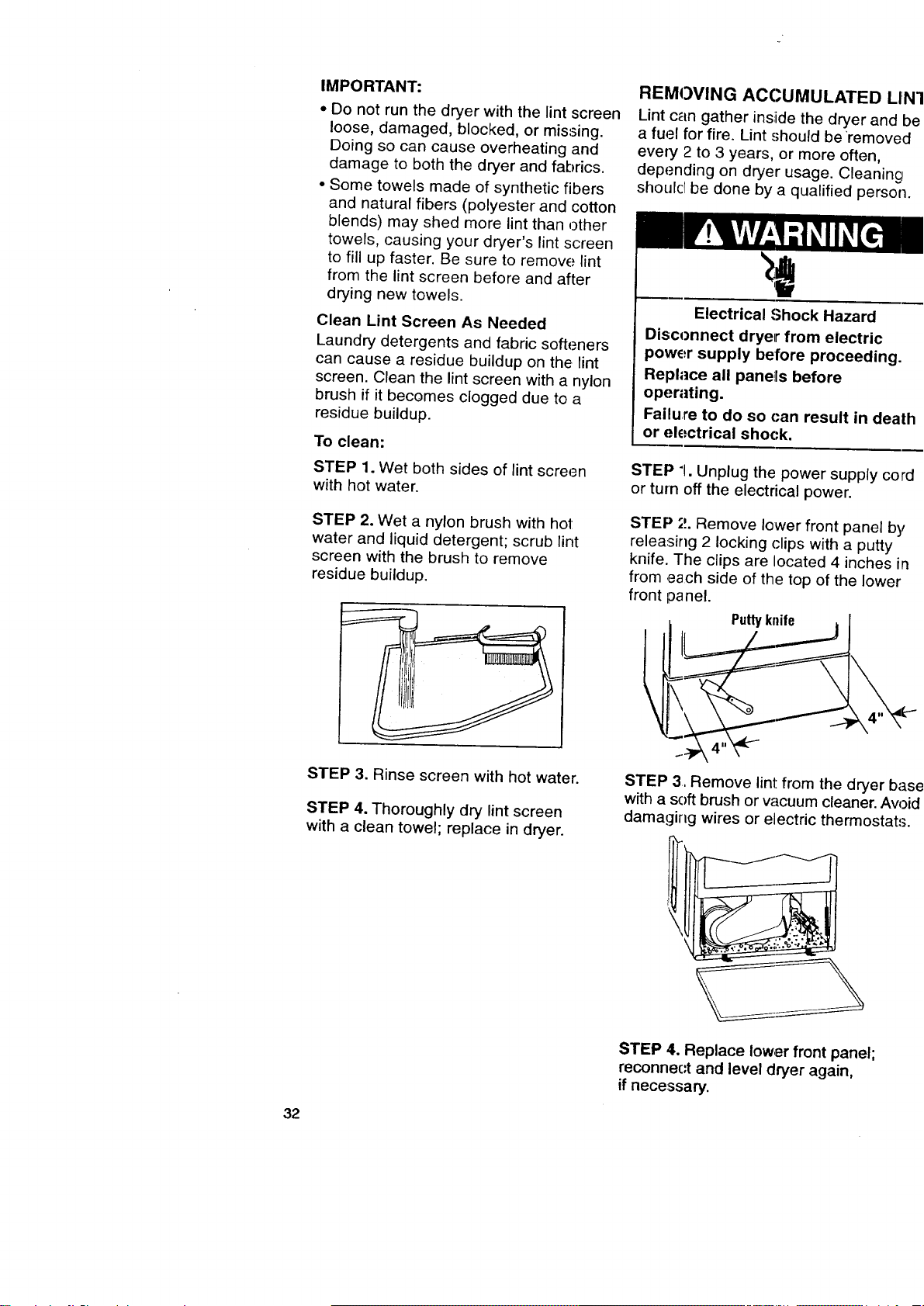
To clean:
STEP 1. Wet both sides of lint screen
with hot water.
STEP 2. Wet a nylon brush with hot
water and liquid detergent; scrub lint
screen with the brush to remove
residue buildup.
STEP 3. Rinse screen with hot water.
STEP 4. Thoroughly dry lint screen
with a clean towel; replace in dryer.
REMOVING ACCUMULATED LIN
Lint can gather inside the dryer and b_
a fuel for fire. Lint should beremoved
every 2 to 3 years, or more often,
depending on dryer usage. Cleaning
shoulcl be done by a qualified person.
Electrical Shock Hazard
Disconnect dryer from electric
power supply before proceeding.
Replace all panels before
operating.
Failure to do so can result in death
or electrical shock.
STEP 7. Unplug the power supply cord
or turn off the electrical power,
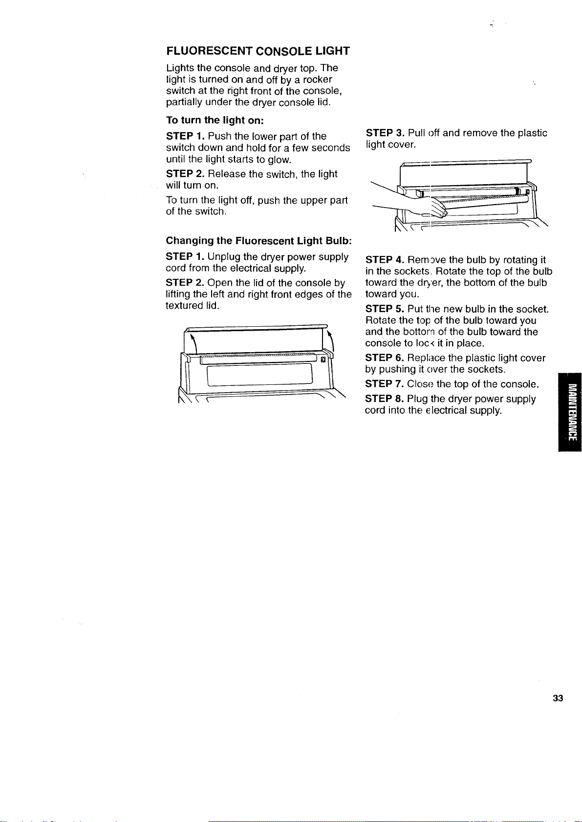
STEP 2. Remove lower front panel by
releasirlg 2 locking (:lips with a putty
knife. The clips are located 4 inches in
from ,each side of the top of the lower
front panel.
Puttyknife I
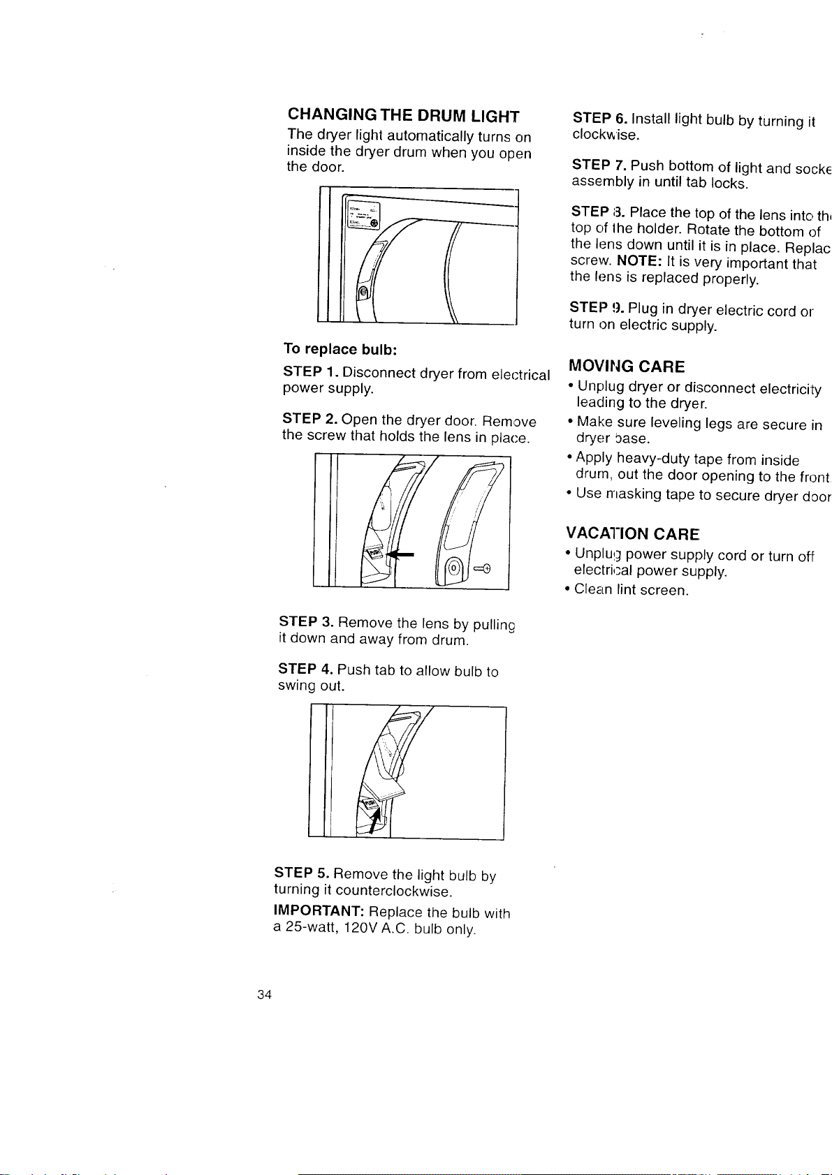
STEP 3, Remove lint from the dryer bas
with a soft brush or w_cuum cleaner. Aw_i(
damaging wires or electric thermostats.
STEP 4. Replace lower front panel;
reconnect and level dryer again,
if necessary.
32
FLUORESCENT CONSOLE LIGHT
Lights the console and dryer top. The
light is turned on and off by a rocker
switch at the right front of the console,
partially under the dryer console lid.
To turn the light on:
STEP 1. Push the lower part of the
switch down and hold for a few seconds
until the light starts to glow.
STEP 2. Release the switch, the light
will turn on.
To turn the light off, push the upper part
of the switch.
Changing the Fluorescent Light Bulb:
STEP 1. Unplug the dryer power supply
cord from the electrical supply.
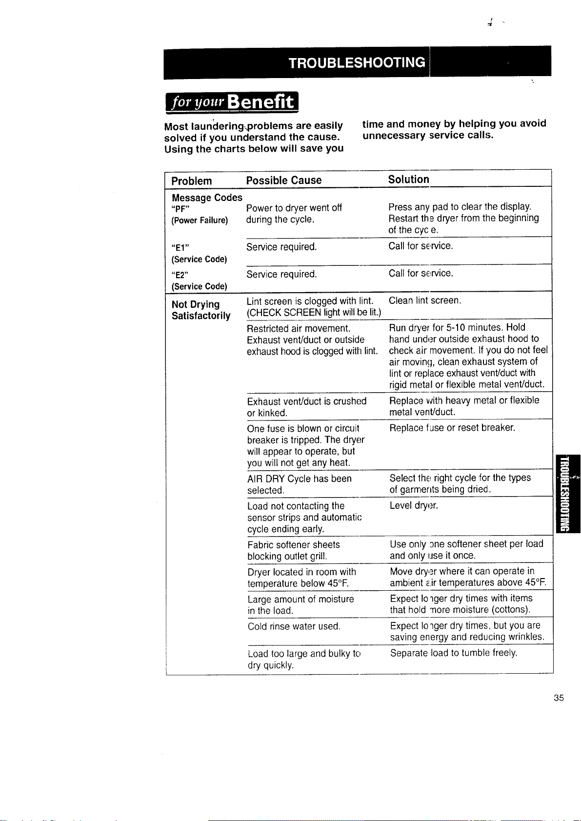
STEP 2. Open the lid of the console by
lifting the left and right front edges of the
textured lid.
STEP 3. Pull off and remove the plastic
light cover.
STEP 4. Remove the bulb by rotating it
in the sockets. Rotate the top of the bulb
toward the dryer, the bottom of the bulb
toward you.
STEP 5. Put the new bulb in the socket.
Rotate the top of the bulb toward you
and the bottom of the bulb toward the
console to Ioc< it in place.
STEP 6. Replace the plastic light cover
by pushing it over the sockets.
STEP 7. Close the top of the console.
STEP 8. Plug the dryer power supply
cord into the; electrical supply.
33
CHANGING THE DRUM LIGHT
The dryer light automatically turns on
inside the dryer drum when you open
the door.
To replace bulb:
STEP 1. Disconnect dryer from electrical
power supply.
STEP 2. Open the dryer door. Remove
the screw that holds the lens in place.
STEP 6. Install light bulb by turning it
clockwise.
STEP 7. Push bottom of light and sock
assembly in until tab locks.
STEP 8. Place the top of the lens into tf
top of lhe holder. Rotate the bottom of
the lens down until it is in place. Repla,
screw. NOTE: It is very important that
the lens is replaced properly.
STEP 9. Plug in dryer electric cord or
turn on electric supply.
MOVING CARE
• Unplug dryer or disconnect electricity
leading to the dryer.
• Make sure leveling legs are secure in
dryer :)ase.
• Apply heavy-duty tape from inside
drum, out the door opening to the fron
• Use masking tape to secure dryer doo
VACATION CARE
• Unplug power supply cord or turn off
electrical power supply.
• Clean lint screen.
STEP 3. Remove the lens by pullin£
it down and away from drum.
STEP 4. Push tab to allow bulb to
swing out.
STEP 5. Remove the light bulb by
turning it counterclockwise.
IMPORTANT: Replace the bulb with
a 25-watt, 120V A.C. bulb only.
34
_t
Most launclering_problems are easily
solved if you understand the cause.
Using the charts below will save you
time and money by helping you avoid
unnecessary service calls.
Problem Possible Cause Solution
Message Codes
"PF" Power to dryer went off Press any pad to clear the display.
(PowerFailure) during the cycle. Restart th£ dryer from the beginning
of the cyc e.
"El" Service required. Call for se,rvice.
(Service Code)
"E2" Service required. Call for service.
(ServiceCode)
Not Drying Lint screen is clogged with lint. Clean lint screen.
Satisfactorily (CHECK SCREEN light will be lit.)
Restricted air movement.
Exhaust vent/duct or outside
exhaust hood isclogged with lint.
Run dryer for 5-10 minutes. Hold
hand under outside exhaust hood to
check a.irmovement. If you do not feel
air moving, clean exhaust system of
lint or replace exhaust w._nt/ductwith
rigid metal or flexible metal vent/duct.
Exhaust vent/duct is crushed Replace with heavy metal or flexible
or kinked, metal vent/duct.
One fuse is blown or circuit Replace fase or reset breaker.
breaker is tripped. The dryer
will appear to operate, but
you will not get any heat.
AIR DRY Cycle has been Select the right cycle for the types
selected, of garments being dried.
Load not contacting the Level dryer.
sensor strips and automatic;
cycle ending early.
Fabric softener sheets Use only one softener sheet per load
blocking outlet grill, and only use it once.
Dryer located in room with Move dry,_r where it can operate in
temperature below 45°E ambient _.irtemperatures above 45°F.
Large amount of moisture Expect Io_ger dry times with items
in the load. that hold more moisture (cottons).
Cold rinse water used. Expect Ioqger dry times, but you are
saving energy and reducing wrinkles.
Load too large and bulky to Separate load to tumble freely.
dry quickly.
35
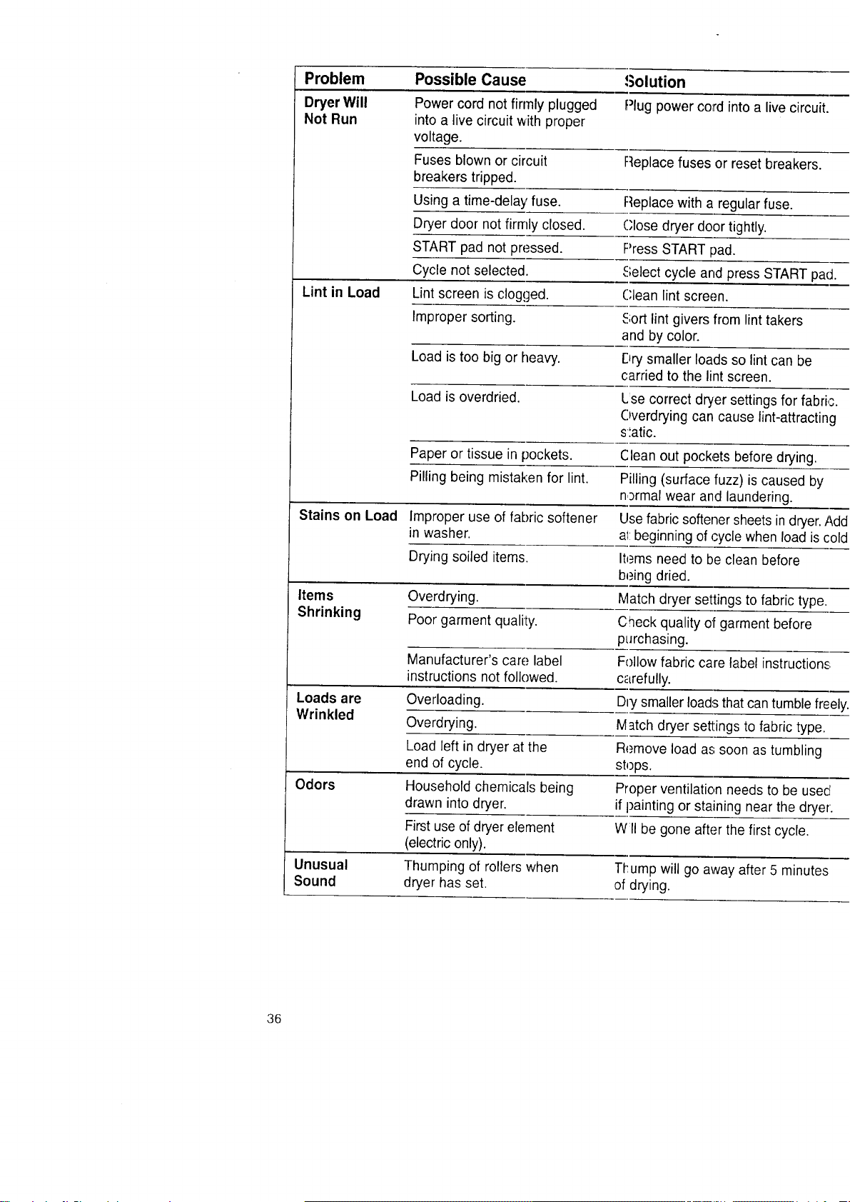
Problem Possible Cause ,Solution
Dryer Will Power cord not firmly plugged Plug powercord intoa live circuit.
Not Run into a live circuit with proper
voltage.
Fuses blown or circuit Replace fuses or reset breakers.
breakers tripped.
Using a time-delay fuse. Replace with a regular fuse.
Dryer door not firmly closed. Close dryer door tightly.
START pad not pressed. Press START pad.
Cycle not selected. Select cycle and press START pa_
Lint in Load Lint screen is clogged. Clean lint screen.
Improper sorting. Sort lint givers from lint takers
and by color.
Load is too big or heavy. Dry smaller loads so lint can be
carried to the lint screen.
Load is overdried. Lse correct dryer settings for fabri,
Overdrying can cause lint-attractin
s_atic.
Paper or tissue in pockets. Clean out pockets before drying.
Pilling being mistaken for lint. Pilling (surface fuzz) is caused by
normal wear and laundering.
Stains on Load Improper use of fabric softener Use fabric softener sheets in dryer.J
in washer, at beginning of cycle when load is c
Drying soiled items. Items need to be clean before
being dried.
Items Overdrying. Match dryer settings to fabric type.
Shrinking Poor garment quality. Check quality of garment before
purchasing.
Manufacturer's car(,,label Follow fabric care label instructions
instructions not followed, carefully.
Loads are Overloading. Dry smaller loads that can tumble fre
Wrinkled Overdrying. Match dryer settings to fabric type.
Load left in dryer at the Remove load as soon as tumbling
end of cycle, stops.
Odors Household chemicals being Proper ventilation needs to be usec
drawn into dryer, if painting or staining near the dryel
First use of dryer element Wll be gone after the first cycle.
(electric only).
Unusual Thumping of rollers when Tl_umpwill go away after 5 minutes
Sound dryer has set. of drying.
36
KENMORE DRYERS
We Service What We Sell
"We Service What We Sell" is our
assurance you can depend on Sears
for service. Your Electric Dryer has
added value when you consider that
Sears has service units nationwide,
staffed with professional technicians
specifically trained on Sears appliances
and having the parts, tools, and equip-
ment to ensure that we meet our pledge
to you..."We Service What We Sell'.'
Sears Maintenance Agreement
Maintain the value of your Kenmore
Electric Dryer with a Sears Maintenance
Agreement. Sears Electric Dryers are
designed, manufactured, and tested for
years of dependable operation. Yet, any
modem appliance may require service
from time to time.
The Sears Maintenance Agreement
• Is your way to buy tomorrow's service
at today's prices.
° Eliminates repair bills resulting from
normal use.
• Allows for as rnany service calls as
required.
• Provides for service by professional
Sears Trained Technicians.
• Even if you don't need repairs, the
Maintenance Agreement offers an
annual preventative maintenance
check-up at your request!
This maintenance agreement does not
cover originall installation, reinstallation,
or damage resLtlting from external causes
such as acts of abuse, theft, fire, flood,
wind, lightning, freezing, power failure,
power reduction, etc.
P
I
37
Forthe repair or replacementpartsyou
needdelivereddirectlyto yourhome
Call7 am - 7 pm, 7 daysa week
1-800-366-PART
(1-800-366-7278)
Forin-home major brandrepair service
Call24 hours aday,7 daysaweek
1-800-4-REPAIR
(1-800-473-7247)
Forthe locationof a Sears Parts and
Repair Center in yourarea
Call24 hours aday,7 daysaweek
1 -800-448-1222
iN mmm
nnn
mm
mmmmmmmm
mmnmmmm
For informationon purchasinga Sears
MaintenanceAgreementor to inquire
aboutan existingAgreement
Call9 am - 5 pm, Monday- Saturday
1-800-827-6655
When requestingserviceor ordering
parts, always givethe following
information:
• Product Type •Part Number
• Model Number • Part Description
SHAR,
38
America'sRepairSpecialists