
Please ll in the following information for your NEW unit, carefully
read the instructions in this manual and le it for future reference.
MODEL NO.
SERIAL NO.
PURCHASED FROM
INSTALL DATE
1-800-523-7138
Continental Refrigerator
A Division of National Refrigeration
& Air Conditioning Products, Inc.
539 Dunksferry Road
Bensalem, PA 19020-5908
P 215-244-1400
F 215-244-9579
www.continentalrefrigerator.com
INSTALLATION AND OPERATIONS MANUAL
Milk Coolers
Forced Air & Cold Wall
SCAN this code
to download manual

Page
Receiving Your New Model ............................................................................................................. 3
General Information and Important Operating Facts ................................................................................ 3
Uncrating Your New Model.............................................................................................................. 3
Installation and Location ................................................................................................................ 4
Ventilation ..............................................................................................................................................................4
Floor Drains and Loads ..........................................................................................................................................4
Cabinet Clean Out Drain and Hose .........................................................................................................................4
Condensate Pan .....................................................................................................................................................5
Door Latch and Lid Lock .......................................................................................................................................6
Latch Adjustment and Lock Replacement ..............................................................................................................6
Removal of Top Assembly .....................................................................................................................................7
Interior Accessories ..............................................................................................................................................................7
Initial Cleaning Procedure .............................................................................................................. 7
Start-Up Procedure ....................................................................................................................... 7
Electrical Connections ............................................................................................................................................7
Start-Up Checklist ..................................................................................................................................................8
Operation................................................................................................................................... 8
Refrigeration System and Adjustment (Cold Wall) ................................................................................................8
Refrigeration System and Adjustment (Forced Air) ...............................................................................................8
Electronic Control Display and Buttons .................................................................................................................9
Initial Sequence of Operation .................................................................................................................................9
How to Calibrate the Electronic Control .................................................................................................................9
How to Change the Set-Point ................................................................................................................................10
Anti-Condensate Control .......................................................................................................................................10
How to Initiate a Manual Defrost ..........................................................................................................................10
How to Change the Defrost Interval ......................................................................................................................10
Electronic Control Error Codes .............................................................................................................................11
Maintenance .............................................................................................................................. 11
Periodic Cleaning Procedure .................................................................................................................................11
General Preventative Maintenance ........................................................................................................................12
Care and Cleaning of Stainless Steel.....................................................................................................................12
Parts and Service ........................................................................................................................ 13
Placing a Service Call ............................................................................................................................................13
Obtaining Replacement Parts Under Warranty .....................................................................................................14
Obtaining Replacement Compressor Under Warranty ..........................................................................................14
End-of-Life Disposal of Refrigerated Equipment ...................................................................................................14
Limited Extended Protection Warranty ............................................................................................... 15
Troubleshooting and Servicing Guide ................................................................................................ 16
Wiring Diagrams ......................................................................................................................... 18
TABLE OF CONTENTS
3
OPERATIONS MANUAL
MILK COOLERS FORCED AIR & COLD WALL
IMPORTANT NOTE: The model and serial number should
be noted on the front cover of this manual, in the spaces
provided. If parts or service are ever needed for your unit,
this information will be required to verify warranty status
and to properly identify any parts that may be needed.
All cabinets must be given sufficient time to reach normal
operating temperature before placing any pre-chilled milk inside
cabinet. Approximately 1 hour of operation is required to lower
the cabinet temperature to 38°F (4°C). During pull-down, doors
and lids should be kept closed (see “Operation” section for
further information).
IMPORTANT NOTE: It is strongly recommended that
top lids and doors be kept in the closed position when
the unit is not in use or between rush periods. This is
extremely important during the summer months and in
hot kitchens. Do not keep the top lids and doors open
for prolonged periods of time and never operate forced
air models for longer than four hours with lids and doors
open as evaporator coil can ice and may have to be manu-
ally defrosted.
Prior to factory shipping, all products are performance-run
tested for a minimum of 12 hours providing a highly sophis-
ticated temperature recording exclusive to each individual
cabinet. This recording is supplied within this manual packet. A
final evaluation, including analysis of cabinet performance, leak
check, vibration, noise level and visual examination is made by a
qualified quality control team to assure a superior product. The
carrier signs to this effect when they accept the product for ship-
ping. To insure the maximum in safety and sanitation, all models
are listed under applicable Underwriters Laboratories and the
National Sanitation Foundation standards.
CAUTION
RISK OF ELECTRICAL SHOCK
KEEP ELECTRICAL COMPONENTS AND CONTROLS DRY
- DO NOT SPRAY WITH WATER!
FAILURE TO FOLLOW THESE INSTRUCTIONS CAN
CAUSE A HAZARD & VOID FACTORY WARRANTY.
UNCRATING YOUR NEW MODEL
The shipping container should remain on your cabinet to avoid
dents or scratches while transporting to the actual set-up loca-
tion. All accessories are carefully packaged and secured inside
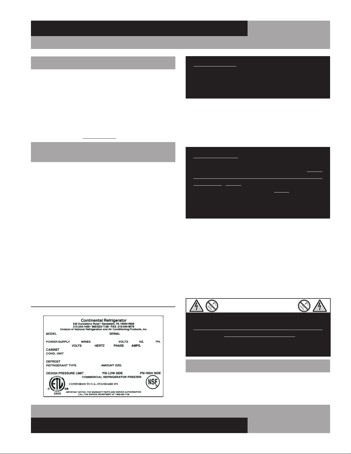
FIGURE 1: Data Tag
RECEIVING YOUR NEW MODEL
Congratulations on your purchase of Continental Refrigerator
superior foodservice equipment! When your shipment arrives,
thoroughly examine the packaging for any punctures, dents or
signs of rough handling. It is in your best interest to partially
remove or open the shipping container to examine the contents
for any missing accessories or concealed damage which may
have occurred during shipment. If the cabinet is damaged, it
must be noted on the carrier’s delivery slip or bill of lading
and a Freight Claim must be filed with the shipping company.
FREIGHT DAMAGE IS NOT COVERED UNDER WARRANTY.
GENERAL INFORMATION AND
IMPORTANT OPERATING FACTS
This manual has been compiled to aid in the installation, opera-
tion and maintenance of your equipment. Please read it and
familiarize yourself with your equipment, its operation and avail-
able accessories, to enjoy optimum performance.
This equipment is prohibited from use in California with
any refrigerants on the “List of Prohibited Substances” for
that specific end-use, in accordance with California Code of
Regulations, title 17, section 95374. This disclosure statement
has been reviewed and approved by NRAC, Inc. and NRAC, Inc.
attests, under penalty of perjury, that these statements are true
and accurate.
SERIAL DATA TAG
A serialized data tag is permanently attached to the inside right-
hand wall of your unit. (see Figure 1). In addition to identifying
the specific product, this label provides important information
regarding electrical requirements and refrigeration charge, as
well as agency listings and factory contacts.

4
MILK COOLERS FORCED AIR & COLD WALL
OPERATIONS MANUAL
IMPORTANT NOTE: For maximum efficiency, your new
cabinet must be located where an unrestricted air supply
can be circulated to the condensing unit. For optimum
performance, a minimum clearance of 3” on each side
and rear of the cabinet should be provided. Your model
has been designed to operate only with the casters sup-
plied. Never obstruct the area below the grill in the front
or rear of the cabinet in any way, and never place or store
anything inside the cabinet machine compartment. These
rules are essential for long life. FAILURE TO FOLLOW
THESE GUIDELINES MAY VOID YOUR WARRANTY.
FLOOR DRAINS AND LOADS
Your milk cooler should be located over top of, or close to, a
building floor drain. The floor should provide level positioning,
be free of vibration and strong enough to support the total com-
bined weights of your new model plus the maximum product
load which might be placed into it. Keep in mind that all the
weight is concentrated at the casters. To estimate the possible
product weight, assume that each cubic foot of storage space
weighs approximately 35 pounds. Multiply 35 pounds by the
amount of cubic feet in the cabinet to obtain the product load
weight.
For example, a 20 cubic foot refrigerator can hold approximately 700
pounds of product (35 x 20). Assuming the cabinet itself weighs 300
pounds, the total combined weight of cabinet and product is approxi-
mately 1000 pounds. Therefore, the floor in this example must be able
to support up to 1000 pounds.
CABINET CLEAN OUT DRAIN AND HOSE
All forced air and cold wall models contain a 1” diameter clean
out drain with a drain stopper and 3’ long ¾” ID drain hose. The
floor drain is located on the bottom right hand floor in the stor-
age compartment. The external drain connection and hose are
accessible behind either the front or rear grill (see Figure 3 for
location). A flexible hose, attached to the drain line under the
cabinet, is located behind the front grill, toward the right hand
side (see Figure 3). The clean out drain hose should be routed
directly to a building floor drain. Never place the hose in the con-
densate pan of your milk cooler. The hose must be positioned
safely so any liquid flows directly into the floor drain and does
not spill onto the floor, to avoid any tripping or slipping hazards.
your cabinet to prevent damage. After moving unit to its final
location, remove all the staples from around the bottom of the
crate using a pry bar. Slide the cardboard carton up and off
the unit, being careful not to rub against the cabinet. Remove
any accessories or boxes on the skid. Dispose of all packaging
materials properly.
Your milk cooler comes with the casters pre-installed. Two
(2) bolts secure the cabinet to the wooden skid. The bolts are
located at each end on the underside of the cabinet. Using a ¾”
socket or open end wrench, remove the bolts. You can now lift
the cabinet off the skid, or carefully knock the wood supports off
each end of the skid and roll your milk cooler off.
IMPORTANT NOTE: Do not under any circumstances, lay
your new model on its front or sides. For a brief period
of time, you may lay the cabinet on its back, but only
when it’s properly blocked so as not to crush the back
or end panels and also to allow provision for your hands,
in order to set it in its upright position without damaging
the cabinet. Do not plug in and operate model for at
least three (3) hours after cabinet is set upright from
being on its back as this can damage the compressor.
INSTALLATION AND LOCATION
Before moving the cabinet to its final point of installation, mea-
sure all doorways or passages to assure sufficient clearance.
VENTILATION
The final location site of your forced air or cold wall refrigerator
must provide a sufficient quantity of cool, clean air. All refrigera-
tion systems operate more efficiently and trouble-free with cool,
dry air circulation. Avoid locations near heat and moisture gen-
erating equipment including ovens, fryers, dishwashers, steam
kettles, etc. Do not install in direct sunlight (where temperatures
may exceed 100°F) or in an unheated area (where temperatures
may drop below 55°F).
Air supply to the condensing unit is critical. Restricting airflow
places excessive heat load on the unit, adversely affecting its
operation and may cause premature failure.
5
OPERATIONS MANUAL
MILK COOLERS FORCED AIR & COLD WALL
IMPORTANT NOTE: It is very important that your milk
cooler is properly level during operation. If it is not level,
doors won’t close properly and gaskets won’t provide a
good seal, which will cause your unit to run excessively.
Excess ice will accumulate inside the cabinet, around the
door openings and on the forced air evaporator coil. If
allowed to continue, ice will eventually block the coil and
the refrigeration system won’t be able to maintain proper
temperature, resulting in loss of product stored inside. In
addition, a cabinet that is not level will allow condensa-
tion water to overflow the pan and spill into the storage
compartment.
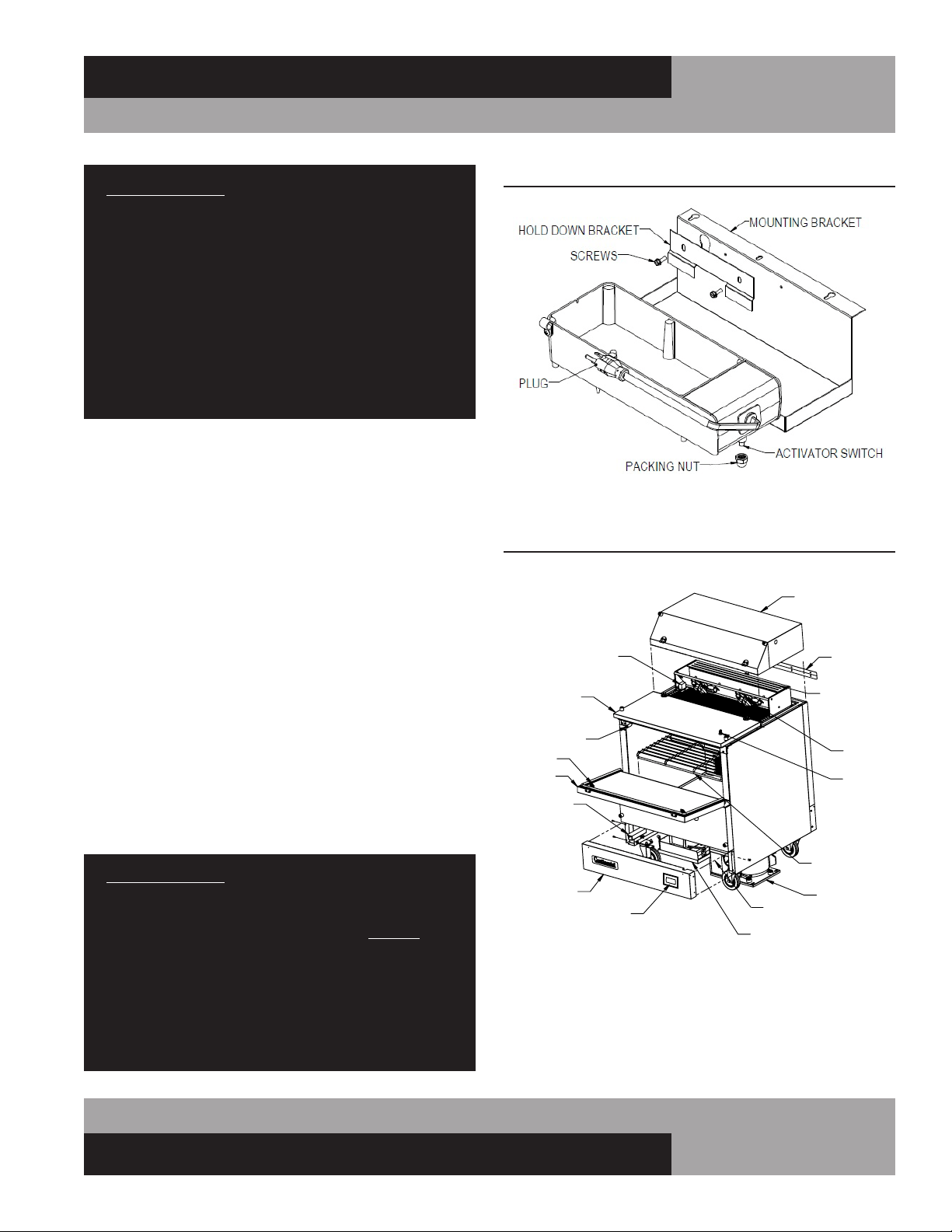
CONDENSATE PAN (Forced Air Models)
All forced air models have a built-in condensate vaporizer on
the underside of the cabinet (see Figure 2A) and are com-
pletely self-defrosting. The activator switch is protected by a
packing nut during shipment. The nut must be removed for
proper operation. Disconnect power by unplugging the cabinet
power cord from the supply. Remove the front grill by taking
out the 2 screws at each end. Gently pull the grill forward,
away from the cabinet, being careful not to damage the tubing
from the thermometer to the sensing bulb. Loosen the screws
securing the hold down bracket and lift the condensate pan
out of the mounting bracket. Remove the packing nut from the
switch and discard the nut. Place the condensate pan back in
the mounting bracket. Plug the power cord into the receptacle
labeled “VAPORIZER” on the control box. Check that the switch
is operating correctly by lightly pressing down on the top of
the pan, at the end where the cord is attached. You will hear a
“click” as pressure is applied and another “click” when pressure
is removed. If you do not hear the switch “click”, ensure the pan
is seated in the bracket correctly and the cord is properly routed
and secured in the clamp. Reinstall the grill and reconnect
power. To clean the vaporizer, follow the steps above.
IMPORTANT NOTE: It is extremely important to ensure
the condensate pan is plugged into the receptacle labeled
“vaporizer” and that the condensing unit is plugged into
the receptacle labeled “condensing unit.” DO NOT con-
nect the floor drain to the condensate pan. The electric
vaporizer is provided to eliminate condensation moisture
only. Placing the floor drain hose in the electric vaporizer
will create unsanitary and unpleasant odors. Water from
the floor drain will also overflow the condensate pan and
spill onto the floor, creating unsafe conditions.
TOP ASSEMBLY
(REMOVED)
EVAPORATOR COIL
(FORCED-AIR ONLY)
JOINING STRIP
FANS
(FORCED AIR)
FRONT GRILL
ELECTRONIC
CONTROL
FRONT DOOR
LATCH KEEPER
LATCH
HINGED LID
TEMP CONTROL
(FORCED AIR
W/MECHANICAL
CONTROL)
LOCK
FLOOR RACK
POWER SUPPLY
(WHEN EQUIPPED)
ELECTRIC VAPORIZER
CONDENSING UNIT
DC POWER SUPPLY
(WHEN EQUIPPED)
FIGURE 2A: Milk Cooler Components (Forced Air Models)
FIGURE 2: Electric Condensate Pan (Forced Air Models)
6
MILK COOLERS FORCED AIR & COLD WALL
OPERATIONS MANUAL
DOOR LATCH AND LID LOCK
To open your milk cooler, unlock the lid by turning the key so
the cam disengages from the keeper (see Figure 4). Lift the lid
and slowly rotate it back, so it rests against the bumpers. Locate
the door latch on the interior side wall. Lift up on the front of
the latch and rotate it back, to disengage it from the keeper.
The door will now freely rotate down. Lower it gently so it rests
against the front bumpers. To close, lift the door back into place
and rotate the latch to engage the keeper. Close the lid by rotat-
ing forward and lower it into place, so the clips engage into the
accepters at each end of the door.
NOTE: The lid clips and accepters secure the door, so
it cannot be opened until after the lid is unlocked and
opened. Always close the door before closing the lid.
LATCH ADJUSTMENT AND LOCK REPLACEMENT
If the lid or door does not close properly, check alignment of
the clips on underside of the lid and the accepters inside the
door (see Figure 4). To adjust, loosen the screws, move clip or
acceptor to position desired and retighten the screws. Use the
same method to adjust the latch keeper if needed. To remove
the lid lock, start on the inside. Use a large philips screwdriver
to turn the lock screw counter-clockwise to loosen it. Remove
the screw and cam. Use a large wrench to turn the nut counter-
clockwise and remove it. From outside the lid, pull the tumbler
out of the hole. To replace the lock, reverse the above steps.
CLIP
ACCEPTER
KEY
LOCK
LOCK KEEPER
DOOR
LATCH KEEPER
TUMBLER
SCREW
CAM
NUT
DOOR LATCH
LID
LID
CLIP
FIGURE 4: Door Latch and Lid Lock
RIGHT SIDE
OF CABINET
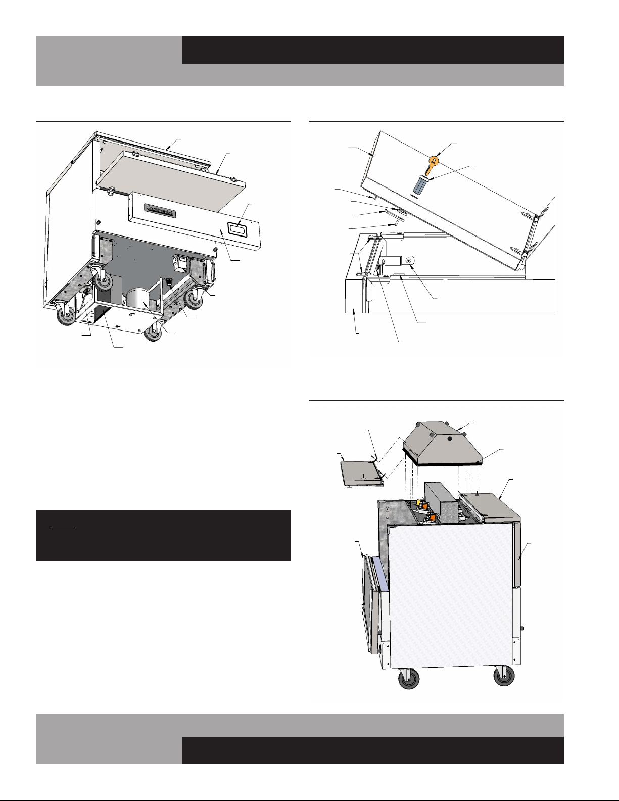
FIGURE 5: Forced Air Top Removal
(Dual Access Model Shown)
SILICONE
SEALANT
TOP ASSEMBLY
FRONT
BACK LID
LID
(SHOWN
OPEN)
HINGE
FRONT DOOR
BACK
DOOR
(REMOVED)
RECEPTACLE
ELECTRICAL
CONDENSER
FRONT GRILL
DRAIN CONNECTION
[COLD-WALL MODELS
W/MECHANICAL CONTROL]
COMPRESSOR
TEMP. CONTROL
LID
FRONT DOOR
(OPENED)
MILK COOLER COMPONENTS
[COLD-WALL MODEL SHOWN]
ELECTRONIC
CONTROL
FIGURE 3: Milk Cooler Components (Cold-Wall Models)

7
OPERATIONS MANUAL
MILK COOLERS FORCED AIR & COLD WALL
START-UP PROCEDURE
ELECTRICAL CONNECTIONS
To insure proper operation, your new model must be connected
to an individual circuit that can supply the full voltage as stated
on the cabinet serial data plate. For correct voltage, power draw,
and wire accommodations, check the data on the serial data
plate located on the inner right wall of your new model. Verify
that this information exactly matches the electrical character-
istics at the installation location. An electrical wiring diagram,
located on the inside compressor compartment rear, next to
the electrical console box, should also be consulted during
connection. For reference, a copy of each electrical wiring dia-
gram is located towards the back of this manual (see “Wiring
Diagrams” section).
Refrigeration compressors are designed to operate within
+/-10% of the rated voltage indicated on the cabinet serial
plate. Excessively high or low supply power can burnout the
compressor. This can be easily detected and will void the fac-
tory warranty. Full voltage at the correct rating, on a separate,
designated circuit, not affected by the operation of other electri-
cal appliances, must be available to the refrigeration unit at all
times. Extension cords should never be used on commercial
equipment, as they can overheat and/or result in low voltage.
GFI/GFCI RECEPTACLES
Ground-Fault Circuit Interrupter (GFCI or GFI) devices are not
recommended for most commercial refrigerators and freez-
ers, since nuisance trips may occur, typically due to moisture.
This can cause temporary loss of power, which may result in
high storage temperatures and potentially unsafe food product.
Building codes in some areas may require certain 115 volt
receptacles to be protected by a GFI If you need to connect your
equipment to a protected circuit, a properly sized, commercial
grade GFI circuit breaker should be used on a separate, isolated
power supply. Or a qualified electrician may be able to hard wire
your equipment, eliminating the need for a GFI device. Contact
Continental’s Service Department before making any modifica-
tions to your cabinet, to avoid loss of warranty.
NOTE: GFI RECEPTACLES ARE NOT RECOMMENDED,
PRODUCT LOSS OR SERVICE PROBLEMS RESULTING
FROM NUISANCE TRIPS, CONNECTION TO A DEFECTIVE
OR IMPROPER POWER SUPPLY, AND UNAUTHORIZED
MODIFICATIONS TO YOUR EQUIPMENT CAN CAUSE A
HAZARD AND WILL VOID FACTORY WARRANTY.
REMOVAL OF TOP ASSEMBLY (Forced Air Models Only)
The top assembly can be removed, by a qualified technician,
to access the evaporator coil, fans and related components
(see Figure 5). Removal and replacement will require a Philips
screwdriver, razor knife, tube of NSF-approved silicone seal-
ant and a silicone gun. To begin, open the front door and lid.
Remove the lid hinge screws from the top assembly. On single
access models, remove the joiner strip and screws from the
back of the cabinet (see Figure 3). For dual access models,
remove the screws from the hinges on the back Llid (see
Figure 4). Set the lid(s), hinges and other parts aside. Use a
razor knife to carefully score the silicone seal around the base
of the top assembly. BE EXTREMELY CAREFUL to avoid cutting
yourself or scratching your milk cooler. From inside the storage
compartment, remove screws from the underside of the top
assembly. Gently lift the top assembly straight up and off the
cabinet. To reattach the top, clean all excess sealant, reverse the
above steps and use silicone to provide an airtight seal between
the top and cabinet.
INTERIOR ACCESSORIES
The standard interior accessory package that is supplied from
the factory with your milk cooler model consists of an epoxy-
coated, steel wire floor rack (see Figure 2) which sits on the
interior stainless steel floor (MC5 models receive two) with the
legs facing down, as shown. A rubber stopper is also provided
for the floor drain.
INITIAL CLEANING PROCEDURE
Prior to start-up and before placing any product inside of your
new model, the interior of the cabinet should be thoroughly
cleaned. Remove the protective film (which is clear on some
models) from all interior sides, bottom and other internal metal
panels, by working the corner loose and slowly pulling the film
back. Washing with a mild soap and warm water solution is
recommended for cleaning the aluminum and stainless steel
surfaces of your cabinet. This should be followed by cleaning
with a baking soda solution (three (3) tablespoons of baking
soda to each quart of warm water). Wipe down thoroughly with
a damp cloth or sponge that has been soaked in clean water and
wrung out thoroughly, and dry with a clean, soft cloth.
IMPORTANT NOTE: Never use harsh detergents, clean-
ers, scouring powders or chemicals when cleaning your
model. Failure to dry the interior surfaces after cleaning
may result in a streaking or staining of the metal.
Complete cleaning procedures and precautions are listed in the
(“Periodic Cleaning Procedure” under “Maintenance”).
8
MILK COOLERS FORCED AIR & COLD WALL
OPERATIONS MANUAL
The system should run smoothly and quietly in accordance with
generally accepted commercial standards. If any unusual noises
are heard, turn the unit off immediately and check for obstruc-
tions of the condenser or evaporator fans. Fan motors, blades,
and housings can be jarred out of position through rough han-
dling in transit.
CAUTION: IF POWER IS DISCONNECTED FOR ANY
REASON, ALLOW 5 MINUTES FOR THE SYSTEM TO
EQUALIZE BEFORE TURNING THE UNIT BACK ON.
DISREGARDING THIS PROCEDURE MAY CAUSE AN
OVERLOAD AND PREVENT THE UNIT FROM OPERATING!
OPERATION
REFRIGERATION SYSTEM AND ADJUSTMENT
(Cold Wall)
All self-contained “cold wall” milk cooler refrigerators are
designed and factory set to maintain an average cabinet temper-
ature of 36°F. Note that adjusting a cabinet too cold (below the
“Cut-In” setting of 30°F) could result in freezing your product
over long periods of time. Further adjustments out of the factory
design temperature range must be made by a qualified refrig-
eration mechanic only. The cold wall system operates by wall
temperatures reaching below freezing (approximate wall tem-
perature is 20°F) and should periodically be manually defrosted
to minimize wall ice accumulation. To manually defrost your
milk cooler, unload all product and place it in a refrigerated stor-
age unit. Keep the lids and doors open, and disconnect power
to the cabinet (by unplugging the power cord) for approximately
30 minutes allowing the frost to melt and drain to the floor drain.
Care should be taken not to scrape and potentially puncture the
wall since the refrigeration tubing is located behind the wall and
could be damaged.
REFRIGERATION SYSTEM AND ADJUSTMENT
(Forced Air)
All self-contained “forced air” milk cooler refrigerators are
designed and factory set to maintain an average cabinet tem-
perature of 36°F. Due to the open-type design and use of milk
coolers, it is normal for condensation to periodically form
around the door and lid seams and hinges, particularly if the
temperature has been set too cold. If moisture becomes exces-
sive check, the control settings (see “How to Change the Set
Point” on page 9) .
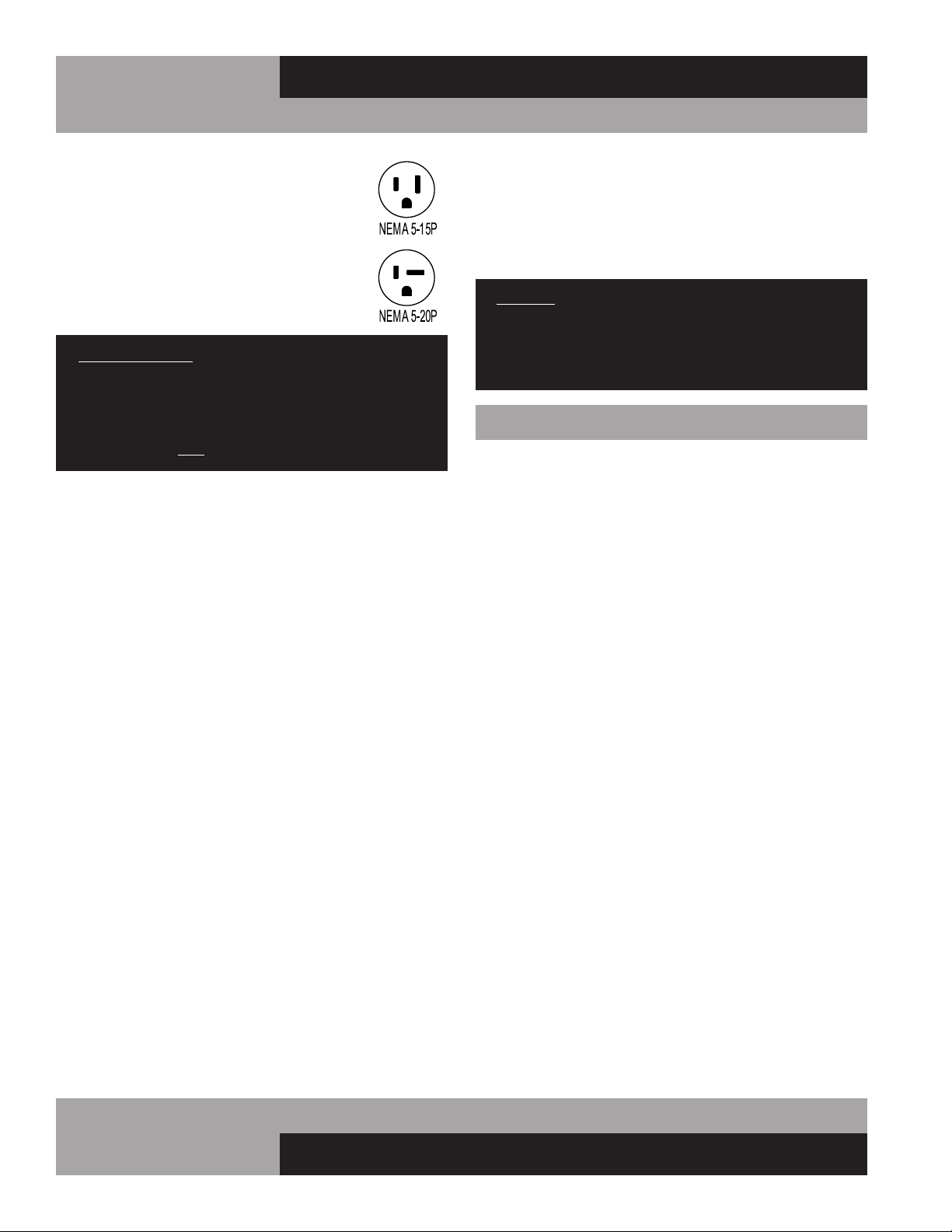
115 VOLT, 60 HZ, 1 PHASE CONNECTION
All 115 volt models are provided with a factory
installed, UL approved 15-amp power cord and
NEMA 5-15P plug, or a 20-amp power cord and
NEMA 5-20P plug. To insure proper operation,
this equipment must be plugged into a NEMA
compatible, grounded receptacle that can supply
the full voltage and amperage stated on the serial
plate (see Figure 1).
IMPORTANT NOTE: A SEPARATE, ISOLATED, PROPERLY
SIZED POWER SUPPLY MUST BE PROVIDED. GFCI
DEVICES AND/OR EXTENSION CORDS SHOULD NOT
BE USED. PRODUCT LOSS, AS WELL AS PROBLEMS
RESULTING FROM NUISANCE TRIPS OR HIGH/LOW
VOLTAGE, ARE NOT COVERED UNDER WARRANTY.
SPECIAL VOLTAGE CONNECTIONS
When models are ordered from the factory with special, optional
voltages, connections should be made as required on the
electrical wiring diagram provided on the inside compressor
compartment rear next to the electrical console box.
START-UP CHECKLIST
After your unit has been installed and power connected in
accordance with this manual, please take time to check the fol-
lowing before loading product, to assure trouble-free operation:
Cabinet location suitable and unit is level
(see “Installation and Location”)
Seperate power supply with correct voltage
(see “Electrical Connections”)
Drain hose routed to floor drain
(see “Installation and Location”)
Vaporizer connected
(see “Evaporator Condensate Removal”)
Doors and lids close and seal properly
(see “Door Latch and Lid Lock”)
Cold Wall Models: Correct cabinet temperature
(see “Cold Wall Refrigeration System and Adjustment”
or “Operation with Electronic Control”)
Forced Air Models: Correct cabinet temperature
(see “Forced Air Refrigeration System and Adjustment”)
or “Operation with Electronic Control”)
Refrigeration lines free of kinks and vibration
(see “Refrigeration System
All packaging discarded and cabinet cleaned
(see “Periodic Cleaning”)
09/03/10
9
OPERATIONS MANUAL
MILK COOLERS FORCED AIR & COLD WALL
a. The display will illuminate with the current cabinet
temperature.
NOTE: If the display does not illuminate, make sure
the main power switch on top of the control box is
set to ON (when provided).
b. The compressor icon, fan icon, and the aux heater icon
may flash for a period of time, indicating normal
delayed start-up.
c. After the start-up delay, the compressor and evaporator
fan(s) will start if the control is calling for cooling. The
fan(s) may pulse on and off when the compressor is off to
conserve energy.
IMPORTANT NOTE: All refrigerators are designed with an
automatic, “off-cycle” defrost system. Defrosting occurs
automatically when the compressor is not operating
during an off-cycle. Do not set the thermostat where
the cabinet temperature will fall below 34°F because the
evaporator will become blocked by ice since the com-
pressor off-cycle will be considerably shortened. This
will result in loss of product stored within the cabinet and
require service to defrost the evaporator and re-adjust
the thermostat, which is not covered under warranty.
CAUTION: ON ALL “FORCED AIR” AND “COLD WALL”
MODELS, IT IS STRONGLY RECOMMENDED THAT TOP
LIDS AND DOORS BE KEPT CLOSED WHEN THE UNIT
IS NOT IN USE OR BETWEEN RUSH PERIODS. THIS
IS EXTREMELY IMPORTANT DURING THE SUMMER
MONTHS AND IN HOT KITCHENS. DO NOT KEEP
THE TOP LIDS AND DOORS OPEN FOR PROLONGED
PERIODS OF TIME AND NEVER OPERATE FORCED AIR
MODELS FOR LONGER THAN FOUR HOURS WITH LIDS
AND DOORS OPEN AS EVAPORATOR COIL CAN ICE
AND MAY HAVE TO BE MANUALLY DEFROSTED.
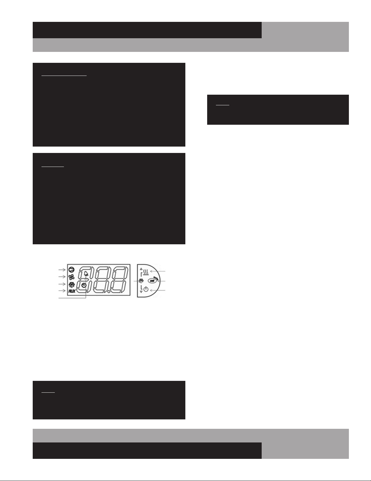
ELECTRONIC CONTROL DISPLAY AND BUTTONS
The control has a 3 button interface.
• The “AUX HTRS/UP” button is used for adjustment of the
auxiliary anti-condensate heaters or for increasing values.
• The “SET/MUTE” button is used to lock in a new value or to
silence the alarm beeper.
• The “DEFROST/DOWN” button is used to activate a manual
defrost or for decreasing values.
The control icons shown above will be illuminated when the
associated function is active. If an icon is flashing, it means the
function will be activated after the controller delays are finished.
NOTE: The electronic control has 3 probes. There is the
regulation probe in the return air stream, there is an
ambient probe, and there is an evaporator probe located
in the evaporator coil.
INITIAL SEQUENCE OF OPERATION
1. Cabinet is plugged in.
2. The control will cycle the compressor on and off determined
by the SET-POINT and DIFFERENTIAL.
3. The control may be preprogrammed to initiate a defrost by
time interval.
HOW TO CALIBRATE THE ELECTRONIC CONTROL
The controller temperature display can be calibrated if required.
Before attempting to calibrate the temperature display, check the
display by placing a pre-calibrated temperature sensing device in
the center of the refrigerated compartment and keep the doors
closed for at least 15 minutes. The temperature display should
read the same temperature as the sensing device, within +/-2°F.
If not, follow these instructions to calibrate.
1. Press and HOLD the “SET” button until “PS” appears flash-
ing in the display. Release the “SET” button.
COMPRESSOR
EVAP FAN
DEFROST
AUX HTRS
ALARM
AUX HTRS
(UP)
SET
(MUTE)
DEFROST
(DOWN)
a. The SET-POINT is the preprogrammed temperature which
shuts off the compressor.
b. The DIFFERENTIAL is the preprogrammed temperature that
is added to the SET POINT temperature that will start the
compressor.
EXAMPLE: Set-Point 36°F and the differential is 4°F the com-
pressor will cycle off at 36°F and back on at 40°F.
a. During defrost, the defrost icon will appear in the display
and the compressor will turn off until a preprogrammed
temperature or time is reached. During this time for freez-
ers only, the evaporator fan(s) will also turn off and the
defrost heater will be energized.
b. After a preprogrammed evaporator temperature has been
reached, there may be a short delay for both the compres-
sor and evaporator fan(s) to restart.
c. After the defrost cycle is completed, the control will
resume normal operation.

10
MILK COOLERS FORCED AIR & COLD WALL
OPERATIONS MANUAL
2. Press the “UP” button until “/C1” appears in the display.
Release the “UP” button.
3. Press and release the “SET” button. The current value of the
offset will appear in the display.
4. Press the “UP” button to increase or the “DOWN” button to
decrease the offset value.
5. Press and HOLD the “SET” button for 5 seconds to confirm
and save the new value. When complete, the current tem-
perature will be displayed. RELEASE the “SET” button.
EXAMPLE: If a sensing device in the cabinet reads 38°F and the
control display shows 41°F, follow steps above and decrease the
current offset by 3°F. If the current offset was 0, change to -3.
HOW TO CHANGE THE SET-POINT
Refrigerators are factory set to maintain an average temperature
of 38°F. Freezers are factory set to maintain an average tempera-
ture of 0°F. To change set-point:
1. Press and HOLD the “SET” button until the current set-point
begins flashing. Release the “SET” button.
2. Press the “UP” or “DOWN” button to adjust to the new set-
point value.
3. Press and release the “SET” button to lock in the new set-
point. The control will now resume normal operation with
the new set-point.
ANTI-CONDENSATE CONTROL
1. To see the current state of the aux heaters (anti-conden-
sate), press and HOLD the “AUX HTR” button for 1 second.
RELEASE the “AUX HTR” button. The display will show the
current state of the heater (“ON” or “OFF”) when the button
is pressed.
2. To change the current state of the AUX Heaters, press and
HOLD the “AUX HTR” button. The display will show the cur-
rent state of heater operation. After 5 seconds, the heater
will switch to the opposite state and the display will return
to displaying the cabinet temperature. RELEASE the button.
The control has a built in energy saving feature for the anti-
condensate (AUX) heaters. When set to ON, the heaters will
automatically energize when conditions require additional heat,
to eliminate condensation. The “AUX” icon on the display will
illuminate when the AUX heaters are energized. To maximize
energy savings, the AUX heaters can be set to OFF, as described
above. In this state, the heaters will never energize. If you ever
notice moisture accumulating on the face of your cabinet, adjust
the AUX control to ON. This will energize the heaters and warm
the face of the cabinet, eliminating any condensation that may
accumulate.
HOW TO INITIATE A MANUAL DEFROST
This is used when a one-time additional defrost may be neces-
sary to clear accumulated ice from the evaporator coil.
1. Press and HOLD the defrost button for 5 seconds.
2. After 5 seconds, the defrost icon will illuminate. RELEASE
the defrost button.
IMPORTANT NOTE: During manual defrost, be sure to
connect your floor drain to a drainage destination.
HOW TO CHANGE THE DEFROST INTERVAL
This is used to increase or decrease the frequency of defrosts.
If the interval is set at “8”, a defrost will occur every 8 hours. If
you need more defrosts, lower this value.
1. Press and HOLD the “SET” button until “PS” appears flash-
ing in the display. Release the “SET” button.
2. Press the “UP” button until “DI” (defrost interval) appears
in the display. Release the “UP” button.
3. Press and RELEASE the “SET” button. The current defrost
interval will appear in the display.
4. Press the “UP” or “DOWN” button to adjust to the new
defrost interval.
5. Press and HOLD the “SET” button to lock in this new value.
When the display returns back to cabinet temperature,
release the “SET” button.
NOTE: Defrost cycles are time initiated and temperature
terminated with a maximum time cut-off.
HIGH AND LOW TEMPERATURE ALARMS
The controller has high and low alarm set-points. These values
can be modified per the end user requirements. There is a pre-
programmed time delay for the alarm to activate to eliminate
nuisance alarms. To change the alarm threshold values:
1. Press and HOLD the “SET” button until “PS” appears flash-
ing in the display. Release the “SET” button.
2. Press the “UP” button until “AL” (Low Alarm Setting) or
“AH” (High Alarm Setting) appears in the display. Release
the “UP” button.
3. Press and RELEASE the “SET” button. The current alarm
setting will be shown.
4. Press the “UP” or “DOWN” button to get the desired alarm
set-point.
5. Press and HOLD the “SET” button for 5 seconds to confirm
and save the new value. When complete, the current tem-
perature will be displayed. Release the “SET” button.
11
OPERATIONS MANUAL
MILK COOLERS FORCED AIR & COLD WALL
NOTE: When in an alarm condition, the display will alter-
nate between the cabinet temperature and alarm code.
“AL” when in a low temperature alarm condition and “AH”
when in a high temperature alarm condition. The control
will also beep and the alarm icon will activate when in an
alarm condition. To silence the alarm beeper for the active
alarm just press and release the “SET/MUTE” button.
ELECTRONIC CONTROL ERROR CODES
When in an alarm condition, the display will alternate between
the alarm code and the current cabinet temperature. The alarm
icon will also illuminate and the beeper will activate. If there is
a regulation probe error, the display will just show alarm code
“E0” and not flash the cabinet temperature. If there is a probe
error, you must contact your service provider immediately.
Alarm Code Alarm Description Notes
E0 Regulation Probe Error Located in return air stream
E1 Evaporator Probe Error Located in evaporator coil
E2 Ambient Probe Error Located on side of electrical box
LO Low Temperature Alarm Reference “AL” parameter
HI High Temperature Alarm Reference “AH” parameter
• Error code “E0”: The control will operate the appliance in
a preprogrammed ON/OFF cycle based on time, not tem-
perature.
• Error code “E1”: The control will still go into a defrost but
will terminate on time, not temperature.
• Error code “E2”: The aux heaters will not operate.
• If the control goes into a high/low temperature alarm, the
beeper will sound and alarm icon will illuminate. When the
temperature goes below the alarm threshold for high tem-
perature alarms or above the alarm threshold for low tem-
perature alarms, the control will go back to normal display.
MAINTENANCE
SAFETY PRECAUTIONS
DISCONNECT POWER BEFORE ATTEMPTING TO WORK
ON OR CLEAN EQUIPMENT. DO NOT ATTEMPT TO
REMOVE ANY COVERS OR PARTS YOURSELF, AS
THIS CAN EXPOSE DANGEROUS, HIGH VOLTAGE
WIRING. SERVICE SHOULD ONLY BE PERFORMED BY
A QUALIFIED TECHNICIAN.
ALWAYS ROUTE POWER CORDS AWAY FROM AREAS
WHERE THEY CAN BE WALKED ON OR DAMAGED BY
OTHER EQUIPMENT. YOUR APPLIANCE IS EQUIPPED
WITH A POLARIZED, GROUNDED POWER PLUG. NEVER
ATTEMPT TO REMOVE THE GROUND POST OR USE
A NON-POLARIZED ADAPTER, WITHOUT PROPERLY
GROUNDING THE EQUIPMENT.
CONDENSER FINS ARE MADE FROM THIN METAL AND
HAVE SHARP EDGES. ALWAYS WEAR GLOVES AND
USE CAUTION WHEN WORKING ON OR AROUND THE
CONDENSING UNIT TO PREVENT CUTS AND AVOID
DAMAGING FINS, TUBING AND OTHER COMPONENTS.
KEEP ELECTRICAL COMPONENTS AND CONTROLS DRY.
DO NOT SPRAY WITH WATER! FAILURE TO FOLLOW
THESE INSTRUCTIONS CAN CAUSE A SAFETY HAZARD
AND VOID FACTORY WARRANTY.
PERIODIC CLEANING PROCEDURE
It is always best to clean your refrigerator or freezer when the
product load in your cabinet is as its lowest level. To clean the
interior or exterior cabinet surfaces, follow these procedures:
1. Disconnect your cabinet from its power supply and remove
all product from inside.
2. Open all doors and allow the cabinet to reach room temp-
erature. Remove all accessories (floor racks, drain plug
stopper, etc.) from inside and wash them with a baking
soda and warm water solution, wipe thoroughly with clean
water.
Dry all accessories completely with a soft clean cloth.
3. Once the cabinet has reached room temperature, wash the
inside and outside surfaces with a solution of warm water
and baking soda. Pay particular attention to the face of the
cabinet, as any residue or debris can impair the door seal.
For slightly more difficult cleanups, ammonia or vinegar in
warm water can be used. Wipe down thoroughly with a
damp cloth or sponge that has been soaked in clean water
12
MILK COOLERS FORCED AIR & COLD WALL
OPERATIONS MANUAL
CARE AND CLEANING OF STAINLESS STEEL*
*Some information and graphics for this section were obtained from “Stainless
Steel Equipment Care and Cleaning” brochure, published by the North American
Association of Food Equipment Manufacturers (NAFEM).
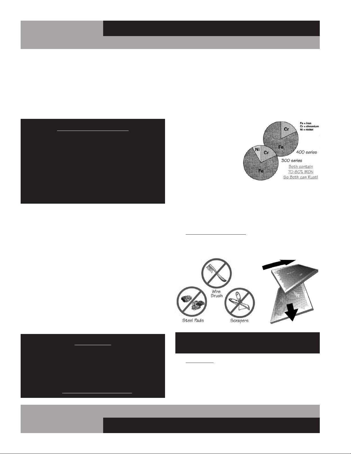
Contrary to popular beliefs, stainless steel can rust, if not prop-
erly cared for and maintained (That’s why it’s called stain-LESS
steel, not stain-PROOF steel.)
All steel is primarily made of
iron. Stainless steels contain
other metals, such as chro-
mium and nickel, that pro-
vide an invisible film on the
surface of the steel that acts
as a shield against corrosion.
As long as this invisible layer
is intact and not broken or
contaminated, the metal will
retain its corrosion protec-
tion and remain stain-less.
There are 3 basic things that can break down the protective
layer on your stainless steel, which must be avoided:
1. MECHANICAL ABRASION is caused by things that
scratch the surface of the metal. Only use soft cloths or
plastic scouring pads to clean and always scrub in the
same directions as the metal grain.
DO NOT USE: steel pads, wire brushes, scrapers or
knives to clean your equipment.
2. CHLORIDES are found in water, salt, food and worst
of all, many cleaners. Only use chloride-free, alkaline-
based, non-abrasive cleaners. Always wipe thoroughly
with cool, clean water and dry with a soft towel. A solu-
tion of 1 tablespoon baking soda mixed with 1 pint water
can be used to remove tough stains.
and wrung out thoroughly, and dry with a clean, soft cloth.
Carefully wash all of the vinyl door gaskets with clean
water, dry them and check for any damage, which may
affect the seal. Failure to dry all surfaces completely may
cause water stains or streaking on the aluminum or stain-
less steel finish.
4. Return all accessories to their original locations, reconnect
the power. Wait at least 1 hour before reloading product.
CLEANING PRECAUTIONS
NEVER USE HARSH DETERGENTS, ABRASIVE
CLEANERS, OR CHEMICALS CONTAINING HALOGENS
(CHLORINE, FLUORINE, IODINE, ETC.) WHEN
CLEANING YOUR UNIT. CONCENTRATED CHEMICALS
CAN CAUSE DISCOLORING, ALWAYS WIPE THEM OFF
IMMEDIATELY IF CONTACT OCCURS. SEE “CLEANING
OF STAINLESS STEEL” FOR MORE INFORMATION.
AVOID SPLASHING THE CABINET WITH WATER AND
CHEMICALS WHEN MOPPING FLOORS OR CLEANING
OTHER EQUIPMENT AROUND IT.
GENERAL PREVENTATIVE MAINTENANCE
The most important thing you can do to maintain any refrigera-
tor or freezer and extend its life, is to keep the condenser clean.
Performance of the air-cooled condensing unit, located under
the cabinet, depends exclusively upon the amount of air passing
through the condenser fins. Your refrigerator or freezer will run
more efficiently, consume less energy, and provide a maximum
of trouble-free service throughout its lifetime if the condenser
coil is kept clean and an adequate supply of clean, cool air is
provided at all times. Periodically (at least once a month) it is
important to inspect the condenser coil for any debris or block-
age that may have accumulated.
If the condenser coil is dirty or dusty, disconnect the cabinet
power supply and use a stiff brush to wipe away any dirt and
debris from the condenser fins. Using a vacuum cleaner with a
brush attachment may aid in this process. After cleaning, restore
electrical service to your cabinet.
IMPORTANT!
AFTER-MARKET CONDENSER FILTERS ARE NOT
PERMITTED BECAUSE THEY HINDER AIRFLOW.
FAILURE TO KEEP THE CONDENSER CLEAN AND
FREE FROM OBSTRUCTIONS WILL CAUSE EXCESSIVE
COMPRESSOR LOAD, REDUCING THE PERFORMANCE
OF YOUR UNIT. THIS CAN RESULT IN PREMATURE
FAILURE AND WILL VOID YOUR WARRANTY.
13
OPERATIONS MANUAL
MILK COOLERS FORCED AIR & COLD WALL
DO NOT USE: abrasive
cleaners, chemicals with
chlorides or muriatic
acid to clean your
equipment.
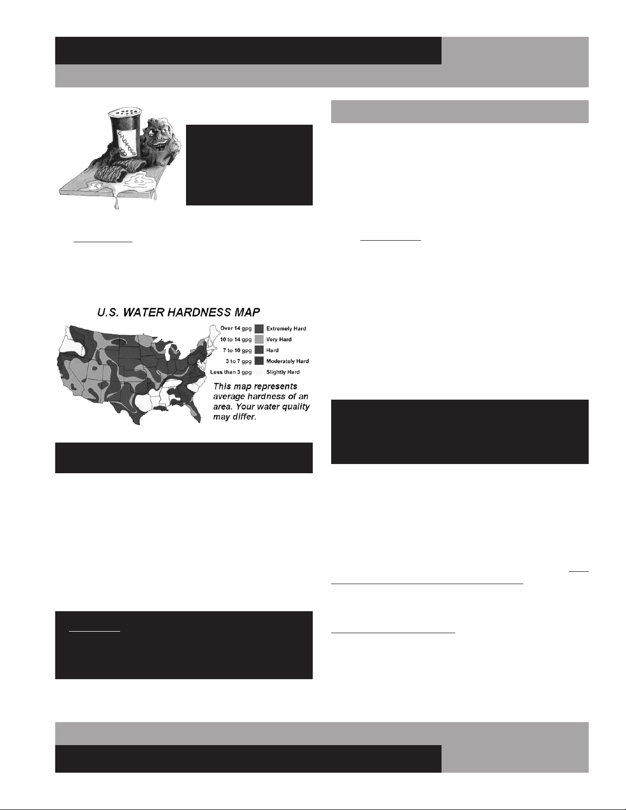
3. HARD WATER causes spots and stains on stainless steel
surfaces, particularly when it is heated. Find out the hard-
ness of your water and treat it properly, if needed. Use a
water filter and softeners if you have hard water. Club soda
can be used to remove streaks or spots.
DO NOT USE: hot or hard water to clean stainless steel.
CLEAN YOUR STAINLESS STEEL REGULARLY using the proper
tools and cleaners. After cleaning, always wipe, wipe, wipe
thoroughly with cool, clean, clear water.
CHECK ALL OF YOUR EQUIPMENT PERIODICALLY. If you see
any signs of rust, clean the area immediately, with a plastic
scrubbing pad. If surface rust is removed promptly, permanent
corrosion, pits and cracks may be avoided. Special stainless
steel polishes, that can help restore the protective coating on
your equipment, are available from a variety of retailers.
IMPORTANT: If these recommendations are not followed,
the protective film on your stainless steel can break down
and your equipment may begin the long walk down the
dark road of corrosion.
PARTS AND SERVICE
Continental is committed to providing the best customer service
in the industry. All new units come with a Limited Extended
Protection Warranty (see “Warranty” section of this manual for
details). If a problem arises with your equipment, please contact
our Service Department at 1-800-523-7138. One of our Service
Specialists will do everything possible to solve the problem as
quickly as possible.
ITEMS NOT COVERED UNDER WARRANTY INCLUDE, BUT ARE
NOT LIMITED TO:
• Preventative maintenance: cleaning condenser
coils and other components.
• Consumables: light bulbs, door gaskets, batteries.
General hardware adjustments: cabinet leveling,
casters/legs, doors/hinges.
• Problems due to: inadequate installation or supply
power; improper maintenance, operation, or abuse.
• Compressor failure due to: dirty condenser, insuffi-
cient clearance/ventilation, excessive temperatures.
• System adjustments and calibrations, including:
controls, thermometer and expansion valves.
Consult the Table of Contents in the front of this man-
ual for detailed information on the items listed above.
Contact Continental’s Service Department with any
additional questions.
PLACING A SERVICE CALL
In order to receive prompt service, always be prepared to pro-
vide your: cabinet model and serial number; cabinet location
name and date installed; contact name and phone number; plus
a description of the problem.
During normal business hours (Monday to Friday, 8am to 5pm
Eastern) contact the Service Department at: 800-523-7138, prior
to any warranty service work being performed.
After normal business hours, or on weekends you can notify our
Service Department by sending an email to:
leaving a message in the general mail box. Be sure to provide the
information listed above. Contact Continental Refrigerator the
following business day, during normal business hours, to verify
the status of your call.

14
MILK COOLERS FORCED AIR & COLD WALL
OPERATIONS MANUAL
OBTAINING REPLACEMENT
PARTS UNDER WARRANTY
If replacement parts are required for a unit under warranty,
contact Continental’s Service Department. New parts will be
sent from the factory and, when applicable, a Return Goods
Authorization (RGA) will be issued to return old parts. The RGA
number must appear on the packaging of any parts returned, or
they will not be accepted. If a service agent uses a part from their
stock, Continental will replace it with a factory part.
OBTAINING REPLACEMENT
COMPRESSOR UNDER WARRANTY
If the compressor should fail within the first twelve (12) months
of use, or within twenty (20) months from the date code on the
compressor, an “over-the-counter” exchange must be made
at an authorized Copeland, Danfoss, Embraco, or Tecumseh
wholesaler.
After the first year, the compressor motor is covered under an
extended “parts only” warranty. The customer is responsible for
any labor charges and any additional parts that may be required.
Contact the Service Department to obtain a replacement com-
pressor through one of the following methods:
• Continental will supply a replacement compressor
at no charge and pay for regular freight. (If expe-
dited freight is requested, the end user, dealer or
service agent is responsible for additional charg-
es and must provide credit card information.
• A compressor can be purchased locally and
Continental will either replace the stock unit with
a new factory compressor, or offer an allowance
towards the purchase of a replacement compres-
sor, up to: $100 for 1/5hp to 1/3hp; $250 for
1/2hp to 3/4hp; $350 for 1hp to 2hp.
The data tag from the defective compressor (or compres-
sor model, serial number and date code, if the tag cannot be
removed) must be included with any reimbursement request.
END-OF-LIFE DISPOSAL
OF REFRIGERATED EQUIPMENT
Your unit is designed and built to provide many years of reli-
able service. At the end of its useful life, please follow the steps
below for safe disposal, to help avoid accidents and to protect
the environment.
1. Remove all doors, to eliminate any potential for accidental
child entrapment.
2. All refrigerant should be removed from the system by a
qualified technician and disposed of properly, or reclaimed.
(Intentional venting of many refrigerants into the air is harm-
ful and prohibited; violators are subject to fines). All refriger-
ant oil should be drained from the compressor and discarded
appropriately.
3. Properly dispose of the cabinet and refrigeration system
components. The majority of the metal in your unit (stainless
steel or aluminum cabinet shell and doors, steel shelving and
compressor, copper refrigerant lines, etc.) can be recycled.
Many recycling facilities will dispose of the unit free of
charge, or pay you for scrap value of the material content.
15
OPERATIONS MANUAL
MILK COOLERS FORCED AIR & COLD WALL
THREE (3) YEAR PARTS AND LABOR WARRANTY
Continental Refrigerator warrants to the original purchaser of every new Continental Refrigerator self contained unit, including all parts thereof, that such equipment is
free from defects in material and workmanship, under normal use, proper maintenance and service as indicated by Continental Refrigerator installation and operation
manual, for a period of three (3) years from the date of installation, or thirty-nine (39) months from the date of shipment from the manufacturer, whichever comes
rst. Normal wear type parts, such as light bulbs/lamps and gaskets are not covered by this warranty. For the purpose of this warranty, the original purchaser shall be
deemed to mean the individual or company for whom the product was originally installed.
Continental Refrigerators obligation under this warranty shall be limited to repairing or replacing, including labor, any part of such product which proves thus defective.
Continental Refrigerator reserves the right to examine any product claimed to be defective. The labor warranty shall be for self-contained units only and for standard
straight time, which is dened as normal service rate time, for service performed during normal working hours. Any service requested outside of a servicer’s normal
working hours will be covered under this warranty for the normal rate and any additional overtime rate will be the responsibility of the equipment purchaser.
Any part determined to be defective in the product should be returned to the company within thirty (30) days under the terms of this warranty and must be accompanied
by the cabinet model, serial number, and identied with a return material authorization number, issued by the manufacturer.
Special installation/applications, including remote locations, are limited in coverage by this warranty. Any installation that requires extra work, and/or travel, to gain
access to the unit for service is the sole responsibility of the equipment purchaser.
Improper operation resulting from factors, including but not limited to, improper or negligent cleaning and maintenance, low voltage conditions, inadequate wiring, and
accidental damage are not manufacturing defects and are strictly the responsibility of the purchaser.
Condenser coils must be cleaned at regular intervals. Failure to do so can cause compressor malfunction and will void warranty. Continental Refrigerator recommends
a minimum monthly cleaning, as stated in the installation and operation manual.
ADDITIONAL TWO (2) YEAR COMPRESSOR PART WARRANTY
In addition to the warranty set forth above, Continental Refrigerator warrants the hermetically/semi-hermetically sealed compressor (part only) for an additional two (2)
years beyond the rst three (3) year warranty period; not to exceed sixty-three (63) months from the date of shipment from Continental Refrigerator, provided upon
receipt of the compressor, manufacturer examination shows the sealed compressor to be defective. This extended warranty does not cover freight for the replacement
compressor or freight for return of the failed compressor. Also, this extended compressor-part only warranty does not apply to any electrical controls, condenser,
evaporator, fan motors, overload switch, starting relay, capacitors, temperature control, lter/drier, accumulator, refrigeration tubing, wiring harness, labor charges, or
supplies which are covered by the standard warranty above.
THE FOREGOING WARRANTIES ARE EXPRESSLY GIVEN IN LIEU OF ALL OTHER WARRANTIES, EXPRESS, IMPLIED, OR STATUTORY, INCLUDING THE IMPLIED
WARRANTIES OF MERCHANTABILITY AND FITNESS FOR A PARTICULAR PURPOSE, WHICH ARE HEREBY DISCLAIMED, ALONG WITH ALL OTHER OBLIGATIONS OR
LIABILITIES ON OUR PART. AND WE NEITHER ASSUME, NOR AUTHORIZE ANY OTHER PERSON TO ASSUME FOR US, ANY OBLIGATION OR LIABILITY IN CONNEC-
TION WITH THE SALE OF SAID REFRIGERATION UNITS OR ANY PARTS THEREOF.
This warranty shall not be assignable and shall be honored only in so far as the original purchaser.
This warranty does not apply outside the limits of the United States of America and Canada, nor does it apply to any part that has been subject to misuse, neglect,
alteration, accident, or to any damage caused by transportation, ood, re, acts of terrorism, or acts of God.
IN NO EVENT SHALL CONTINENTAL REFRIGERATOR BE LIABLE FOR CONSEQUENTIAL, SPECIAL OR PUNITIVE DAMAGES. THE REMEDIES OF PURCHASER SET
FORTH HEREIN ARE EXCLUSIVE AND THE TOTAL LIABILITY OF CONTINENTAL REFRIGERATOR, WHETHER BASED ON CONTRACT, WARRANTY, NEGLIGENCE, IN-
DEMNIFICATION, STRICT LIABILITY, TORT, OR OTHERWISE, SHALL NOT EXCEED THE PURCHASE PRICE OF THE COMPONENT UPON WHICH LIABILITY IS BASED.
CONTINENTAL REFRIGERATOR SHALL HAVE NO OBLIGATION OR LIABILITY FOR CONSEQUENTIAL OR SPECIAL DAMAGES, INCLUDING BUT NOT LIMITED TO
INDIRECT, PUNITIVE DAMAGES, LOSS OF USE, LOSS OF PRODUCT, DOWNTIME OR LOST PROFITS, ARISING OUT OR, RELATED TO OR CONNECTED IN ANY WAY
WITH THE PRODUCT OR ITS USE.
A Division of National Refrigeration & Air Conditioning Products, Inc.
539 Dunksferry Road • Bensalem, PA 19020-5908
P 215-244-1400 • 1-800-523-7138 • F 215-244-9579
www.continentalrefrigerator.com
WARRANTY United States of America & Canada
16
MILK COOLERS FORCED AIR & COLD WALL
OPERATIONS MANUAL
PROBLEM PROBABLE CAUSE CORRECTION
Condensing unit will not
start - no hum.
1. Line disconnected, switch open.
2. Fuse removed or blown.
3. Overload protector blown.
4. Control “Off” due to cold location.
5. Control stuck in open position.
6. Wiring improper or loose.
1. Close start or disconnect switch.
2. Replace Fuse.
3. Determine reason and correct/replace.
4. Relocate control.
5. Repair or replace control.
6. Check wiring against diagram.
Condensing unit will not
start - hums but trips on
overload protector.
1. Improperly wired.
2. Low voltage to unit.
3. Starting capacitor defective.
4. Relay failing to close.
5. Compressor motor has a shorted or open
winding.
6. Internal mechanical trouble in compressor.
7. Insufcient air supply.
1. Check wiring against diagram.
2. Determine reason and correct.
3. Determine reason and replace.
4. Determine reason and replace.
5. Replace compressor.
6. Replace compressor.
7. Clear condenser and allow compressor
to cool down.
Condensing unit starts
and runs, but short
cycles on overload
protector.
1. Additional current passing through overload
protector.
2. Low voltage unit.
3. Overload protector defective.
4. Run capacitor defective.
5. Excessive discharge pressure.
6. Excessive suction pressure.
7. Insufcient air supply.
1. Check wire diagram. Check for added
components connected to wrong side of
overload protector.
2. Determine reason and correct.
3. Check current, replace protector.
4. Determine reason and replace.
5. Check ventilation, restrictions in cooling
medium or refrig. system.
6. Check for misapplication.
7. Clear condenser and allow compressor
to cool down.
Condensing unit starts,
but fails to switch off of
“start” winding.
1. Improperly wired.
2. Low voltage to unit.
3. Relay failing to open.
4. Run capacitor defective.
5. Excessively high discharge pressure.
6. Compressor motor has a shorted or open
winding.
7. Internal mechanical trouble in compressor.
1. Check wiring against diagram.
2. Determine reason and correct.
3. Determine reason and replace.
4. Determine reason and replace.
5. Check discharge shut-off valve, possible
overcharge.
6. Replace compressor.
7. Replace compressor.
Condensing unit runs,
but short cycles on:
1. Overload protector.
2. Thermostat.
3. High pressure cut-out due to:
(a) Insufcient air supply.
(b) Overcharge.
(c) Air in system.
4. Low pressure cut-out due to:
(a) Valve leak.
(b) Undercharge.
(c) Restriction in expansion device.
1. Check current, replace protector.
2. Differential setting must be widened.
3.
(a) Check air supply to condenser.
(b) Evacuate and re-charge.
(c) Evacuate and re-charge.
4.
(a) Replace, evecuate and re-charge.
(b) Evacuate and re-charge.
(c) Replace expansion device.
Condensing unit runs,
but for prolonged peri-
ods or continuous.
1. Shortage of refrigerant.
2. Control contacts stuck closed.
3. Excessive heat load placed into cabinet.
4. Prolonged or too frequent door openings.
5. Evaporator coil iced.
6. Restriction in refrigeration system.
7. Dirty condenser.
8. Filter drier clogged.
1. Fix leak, evacuate and re-charge.
2. Clean contacts or replace control.
3. Allow unit sufcient time for removal of latent
heat.
4. Plan or organize schedule to correct condition.
5. Defrost evaporator coil.
6. Determine location and remove.
7. Clean condenser coil.
8. Replace, evacuate and re-charge.
TROUBLESHOOTING GUIDE
17
OPERATIONS MANUAL
MILK COOLERS FORCED AIR & COLD WALL
TROUBLESHOOTING GUIDE
PROBLEM PROBABLE CAUSE CORRECTION
Start capacitor open,
shorted or blown.
1. Relay contact not opening properly.
2. Prolonged operation on start cycle:
(a) Low voltage to unit.
(b) Improper relay.
(c) Starting load too high.
3. Excessive short cycling.
4. Improper capacitor.
1. Clean contacts or replace relay.
2.
(a) Determine reason and correct.
(b) Replace with correct relay.
(c) Correct by using pump down.
3. See “Condensing Unit Short Cycles” above.
4. Determine correct size and replace.
Run capacitor open,
shorted or blown.
1. Improper capacitor.
2. Excessively high line voltage, over 110%
of rated maximum.
1. Check size and replace.
2. Determine reason and correct.
Relay defective or blown
out.
1. Incorrect Relay.
2. Incorrect mounting angle.
3. Voltage too low or too high.
4. Excessive short cycling.
5. Loose or vibrating mounting position.
6. Incorrect run capacitor.
7. Loose wiring on relay or overload.
1. Check relay and replace.
2. Remount relay in correct position.
3. Determine reason and correct.
4. See “Condensing Unit Short Cycles” above.
5. Remount rigidly.
6. Replace with proper capacitor.
7. Tighten all wiring screws.
Product zone
temperature too high.
1. Control setting too high.
2. Inadequate air circulation.
3. Dirty condenser.
1. Adjust T-stat.
2. Rearrange product load to improve air
circulation.
3. Clean condenser coil.
Suction line frosted or
sweating.
1. Overcharge of refrigerant.
2. Evaporator fan not running.
3. Expansion valve stuck open.
4. Expansion valve superheat too low.
1. Evacuate and re-charge.
2. Determine reason and correct.
3. Clean valve, evacuate and re-charge.
4. Adjust superheat to required setting.
Liquid line frosted, cold
or sweating.
1. Restriction in drier strainer.
2. Liquid line service valve partially closed.
1. Replace drier, evacuate and re-charge.
2. Open valve fully or replace if necessary.
Noisy condensing unit. 1. Loose parts or mounting.
2. Tubing rattle or vibration.
3. Bent fan blade causing excessive vibration.
4. Fan bearings worn.
1. Tighten all mounting parts and shroud cover.
2. Reform tubing to be free of contact.
3. Replace fan blade.
4. Replace fan motor.
Thermometer reads
different than actual
temperature.
1. Calibration.
2. Defective.
1. Consult Operations Manual and calibrate.
2. Replace.
Water leak inside unit. 1. Condensate drain pan not installed properly.
2. Unit not level.
3. Drain pan misaligned.
4. Defective drain pan.
1. Consult Operations Manual for install
instructions.
2. Make sure unit is level or pitched back slightly.
3. Make sure drain pan is aligned properly.
4. Replace.
Doors misaligned. 1. Shifted during shipping. 1. Refer to Operation Manual for hinge
adjustment.
18
MILK COOLERS FORCED AIR & COLD WALL
OPERATIONS MANUAL
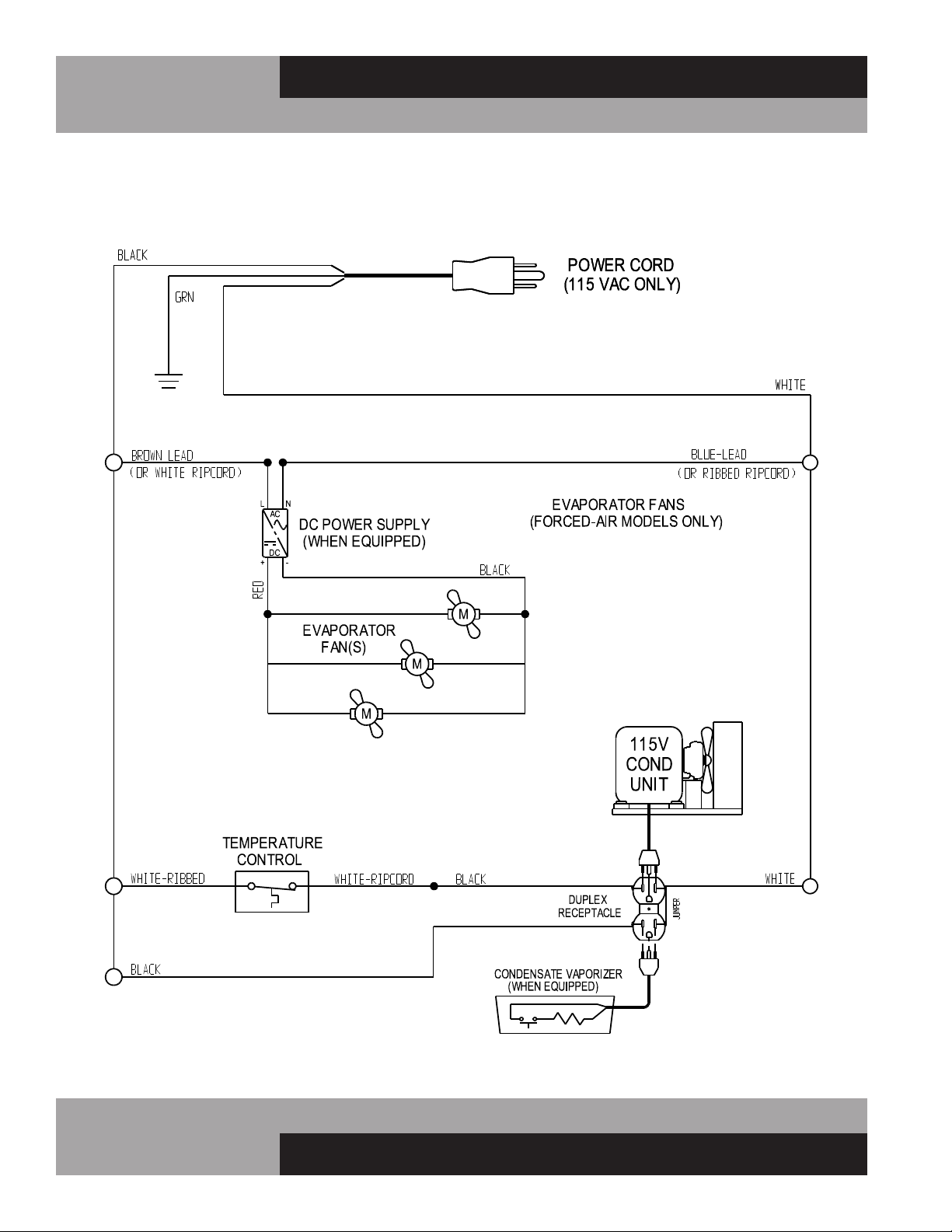
MILK COOLERS (FORCED AIR & COLD WALL MODELS) 115/60/1
WD-R5 WIRING DIAGRAM
19
OPERATIONS MANUAL
MILK COOLERS FORCED AIR & COLD WALL
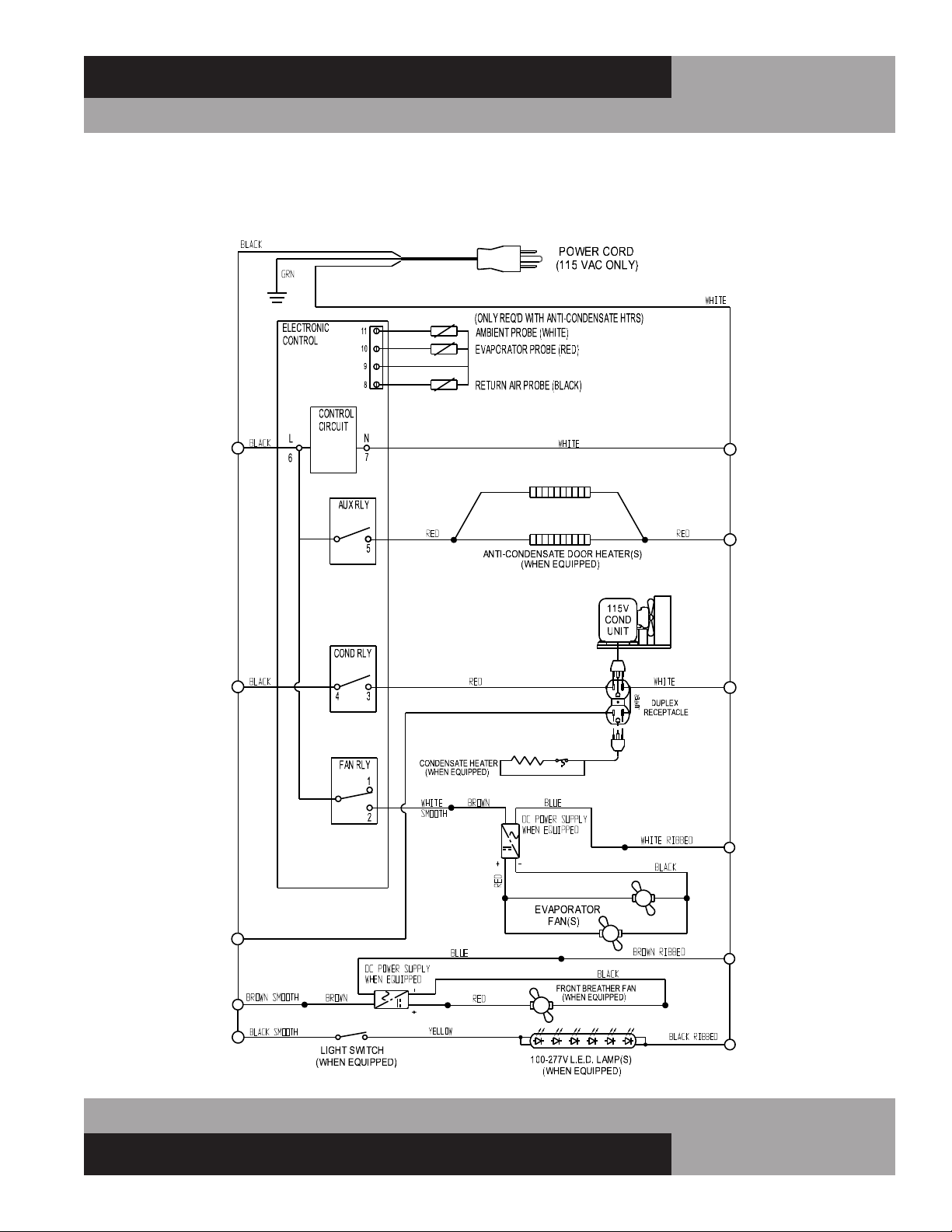
MILK COOLERS (FORCED AIR & COLD WALL MODELS) 115/60/1
W/ELECTRONIC CONTROL WD-R5-EC WIRING DIAGRAM
A Division of National Refrigeration & Air Conditioning Products, Inc.
539 Dunksferry Road • Bensalem, PA 19020-5908
P 215-244-1400 • 1-800-523-7138 • F 215-244-9579
www.continentalrefrigerator.com
IM-MC-Blue-50188-20191111
®