Loading ...
Loading ...
Loading ...
• Loosenknob(Figure7,KeyNo.14).PlaceV-belton
motoranddrivepulleys(Figure8,KeyNos.46and
5O).
• TensionV-beltbypushingdownonmotormount
plateandtighteningknob.Beltisproperlytensioned
whenlightpressureappliedtomidpointofthebelt
producesabout1/2"deflection.
• Makesurebladeteetharepointingdowntowards
table.Turnbladeinsideoutifnecessary.
• Rotatehandwheel(Figure8,KeyNo.23)counter-
clockwisetomovebladewheelstowardseachother.
• Loosenhandle(Figure9,KeyNo.30).Rotateknob
(Figure9,KeyNo.22)tolowerupperbladeguide
assemblyaslowaspossible.
• Loosentwoscrews(Figure9,KeyNo.5).Remove
bladeguard(Figure9,KeyNo.4).
• Slipbladeoverupperandlowerbladewheels,and
centerbladeonbladewheels.Slidebladein
betweenbladeguides.
• Replacebladeguardandsecureinplacebytighten-
ingscrews.Raiseupperbladeguideassembly.
• Rotatehandwheelclockwisetotensionblade.
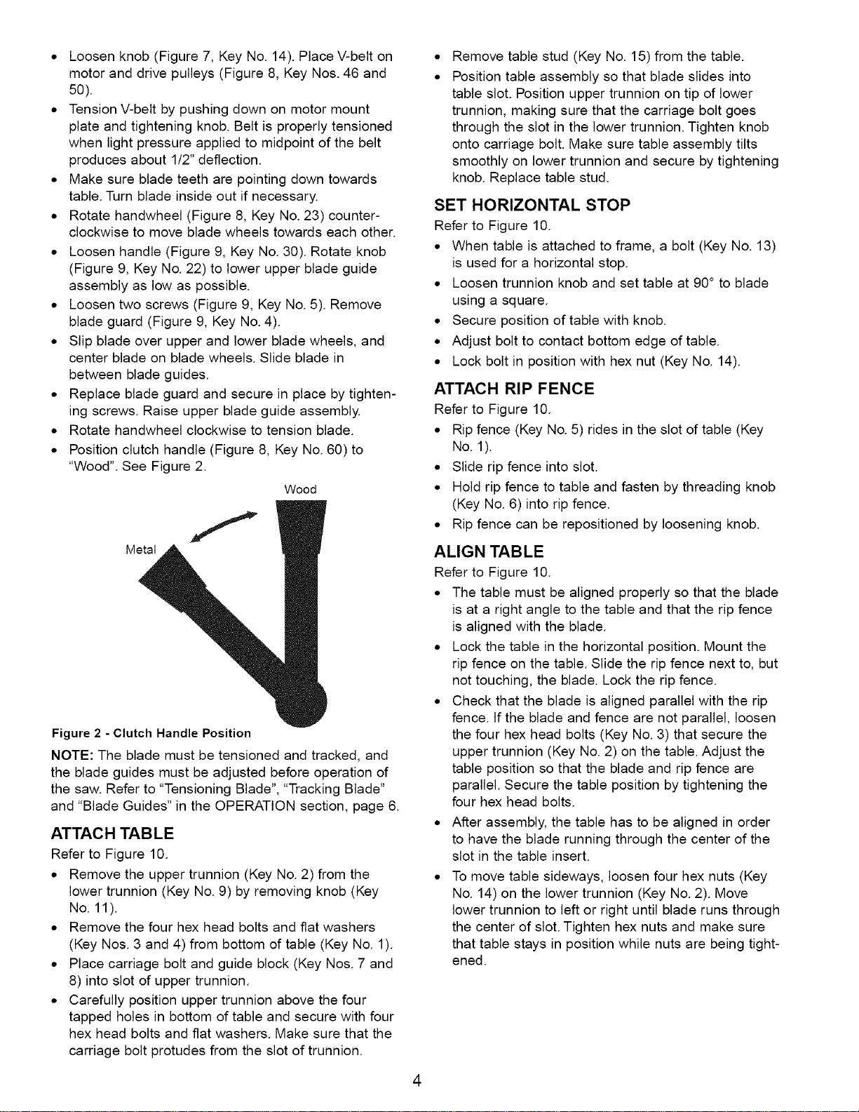
• Positionclutchhandle(Figure8,KeyNo.60)to
"Wood".SeeFigure2.
Wood
Metal
Figure 2 - Clutch Handle Position
NOTE: The blade must be tensioned and tracked, and
the blade guides must be adjusted before operation of
the saw. Refer to "Tensioning Blade", "Tracking Blade"
and "Blade Guides" in the OPERATION section, page 6.
ATTACH TABLE
Refer to Figure 10.
• Remove the upper trunnion (Key No. 2) from the
lower trunnion (Key No. 9) by removing knob (Key
No. 11).
• Remove the four hex head bolts and flat washers
(Key Nos. 3 and 4) from bottom of table (Key No. 1).
• Place carriage bolt and guide block (Key Nos. 7 and
8) into slot of upper trunnion.
• Carefully position upper trunnion above the four
tapped holes in bottom of table and secure with four
hex head bolts and flat washers. Make sure that the
carriage bolt protudes from the slot of trunnion.
Remove table stud (Key No. 15) from the table.
Position table assembly so that blade slides into
table slot. Position upper trunnion on tip of lower
trunnion, making sure that the carriage bolt goes
through the slot in the lower trunnion. Tighten knob
onto carriage bolt. Make sure table assembly tilts
smoothly on lower trunnion and secure by tightening
knob. Replace table stud.
SET HORIZONTAL STOP
Refer to Figure 10.
• When table is attached to frame, a bolt (Key No. 13)
is used for a horizontal stop.
• Loosen trunnion knob and set table at 90° to blade
using a square.
• Secure position of table with knob.
• Adjust bolt to contact bottom edge of table.
• Lock bolt in position with hex nut (Key No. 14).
ATTACH RIP FENCE
Refer to Figure 10.
• Rip fence (Key No. 5) rides in the slot of table (Key
No. 1).
• Slide rip fence into slot.
• Hold rip fence to table and fasten by threading knob
(Key No. 6) into rip fence.
• Rip fence can be repositioned by loosening knob.
ALIGN TABLE
Refer to Figure 10.
• The table must be aligned properly so that the blade
is at a right angle to the table and that the rip fence
is aligned with the blade.
• Lock the table in the horizontal position. Mount the
rip fence on the table. Slide the rip fence next to, but
not touching, the blade. Lock the rip fence.
• Check that the blade is aligned parallel with the rip
fence. If the blade and fence are not parallel, loosen
the four hex head bolts (Key No. 3) that secure the
upper trunnion (Key No. 2) on the table. Adjust the
table position so that the blade and rip fence are
parallel. Secure the table position by tightening the
four hex head bolts.
• After assembly, the table has to be aligned in order
to have the blade running through the center of the
slot in the table insert.
• To move table sideways, loosen four hex nuts (Key
No. 14) on the lower trunnion (Key No. 2). Move
lower trunnion to left or right until blade runs through
the center of slot. Tighten hex nuts and make sure
that table stays in position while nuts are being tight-
ened.
4
Loading ...
Loading ...
Loading ...