Loading ...
Loading ...
Loading ...
10 49-5000406 Rev. 5
E. MECHANICAL NON-DUCTED
INSTALLATION (RARMN_ _)
1. From inside the RV, double check the gasket’s
position and alignment above the roof opening.
Adjust if necessary. The air conditioner can be
moved and adjusted by pushing upwards from
inside the RV.
2. Reach through the base pan and pull the electrical
power cord from the air conditioner through the
ceiling opening.
3. Measure ceiling to roof thickness.
4. Cut rows from the bottom of the foam baffle
according to the table below:
Ceiling to roof thickness (in) Rows to cut
Minimum Maximum
22.510
2.5 3 8
3.5 4 6
4.5 5 4
55.52
5.5 6 0
Best Practice:
Cut away one row at a time and check installation
position of baffle. With the top foam compressed
onto the air conditioner’s base pan, the bottom of the
baffle should be flush to the ceiling opening.
5. Install 2 baffle retainer plates onto the ceiling
assembly (Optional).
6. Place foam baffle into position between 2 retainer
plates.
7. Push the mounting template into the roof opening,
and begin hand-threading each of the 4 mounting
bolts through the nuts in the base pan.
8. Tighten the 4 bolts evenly to 35 ± 5 inch pounds
using a torque wrench at least rated for 0-60 in-lbs.
Even compression is required to prevent leaks
through the gasket.
9. Remove 6 pin connection cover from the ceiling
assembly.
E. MECHANICAL CONTROL
INSTALLATION
(cont.)
10. Plug 6 pin connector from the roof mounted air
conditioner into the electronic control box.
11. Reassemble the 6 pin connection cover to the
ceiling assembly.
12. Remove junction box cover.
13. Route the 115 VAC power cord through the strain
relief of the ceiling assembly. Tighten the strain
relief, making sure not to damage the wires.
8VLQJZLUHFRQQHFWRUVFRQQHFWOLQHWREODFN
neutral to white, and ground to green.
8VLQJHOHFWULFDOWDSHVHFXUHWKHFRQQHFWRUWR
prevent any potential movement due to vehicle
vibration.
16. Push wires and connections into the junction box.
Reinstall junction box cover.
17. Align plastic ceiling panel to the metal assembly.
18. Install the 2 control knobs.
19. Install the 2 provided sheet metal screws to attach
the plastic panel to the metal assembly. The filter
must be removed to install these screws.
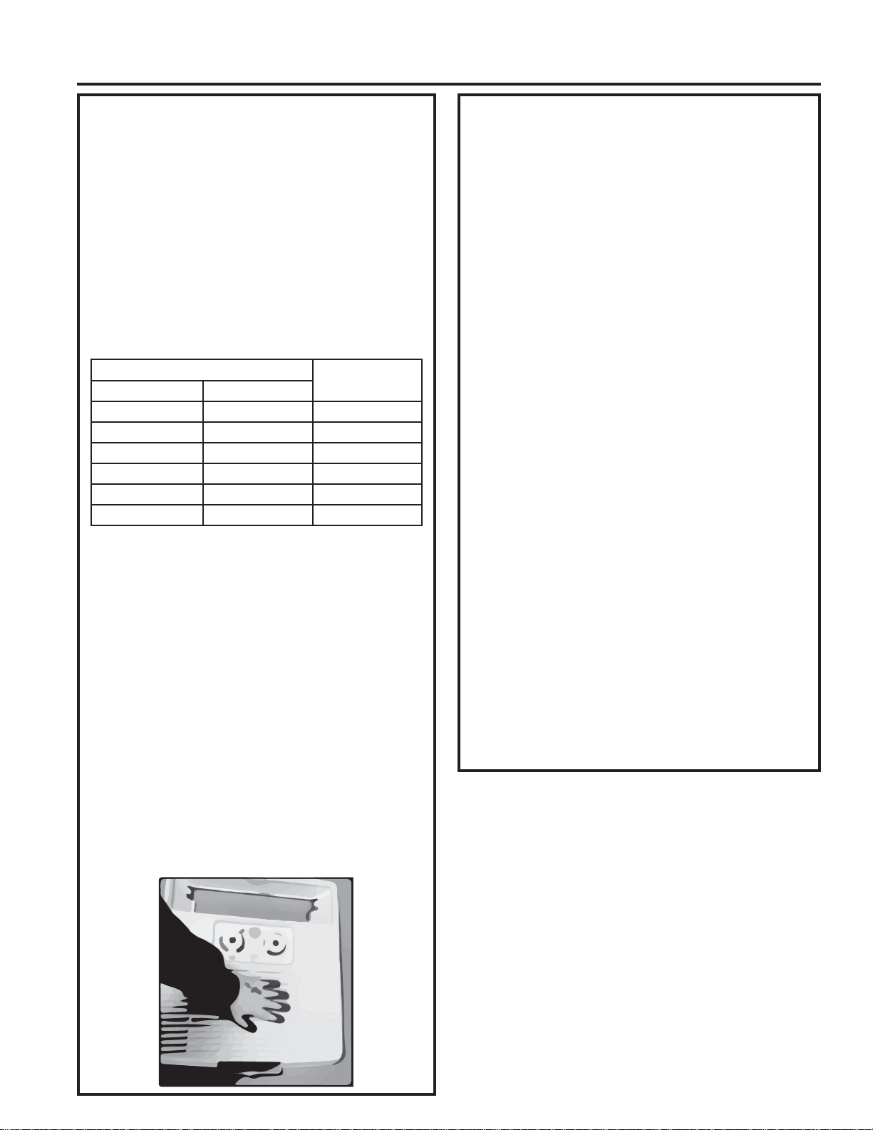
20. Apply pressure to the center of the plastic panel,
drive the 2 wood screws at the location shown in
the figure below. The air discharge doors should
be partially open; otherwise, these screws will be
difficult to drive.
21. Drive the remaining 6 wood screws. The air
discharge doors should be hinged partially open;
otherwise, these screws will be difficult to drive.
22. Assemble the filter to the plastic panel.
23. Installation is complete. Refer to “Controls” on
page 12 before attempting to operate the air
conditioner.
Installation Instructions
INSTALLATION INSTRUCTIONS
Loading ...
Loading ...
Loading ...