Loading ...
Loading ...
Loading ...
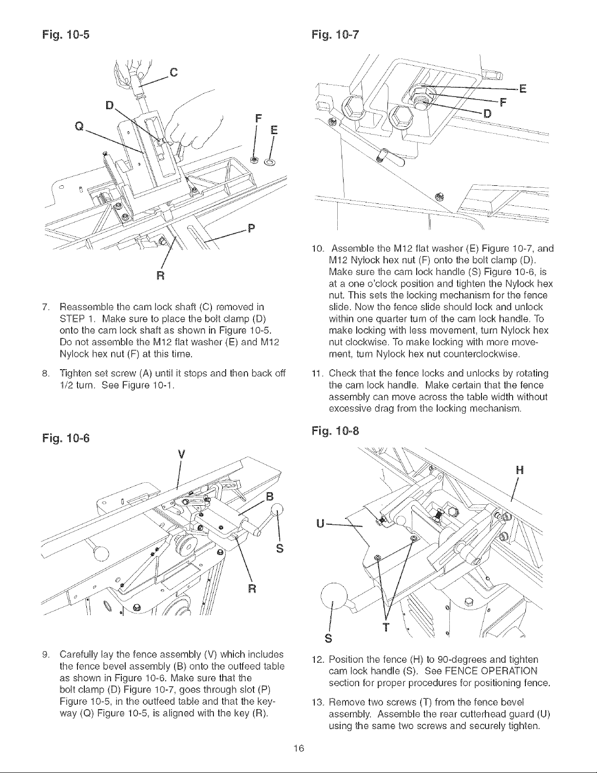
Fig. 10-5 Fig. 10-7
E
7,
5,
Reassembb the cam lock shaft (C) removed in
STEP 1, Make sure to place the bolt clamp (D)
onto the cam lock shaft as shown in Figure 10-5,
Do not assembb the M12 fiat washer (E) and M12
Nylock hex nut (F) at this time,
Tighten set screw (A) until it stops and then back off
1/2 turn, See Figure 10-1,
Fig. 10-6
10,
11,
Assemble the M12 fiat washer (E) Figure 10-7, and
M12 Nylock hex nut (F) onto the bolt clamp (D),
Make sure the cam lock handle (S) Figure 10-6, is
at a one o'clock position and tighten the Nyloek hex
nut, This sets the locking mechanism for the fence
slide, Now the fence slide should lock and unlock
within one quarter turn of the cam lock handle, To
make locking with less movement, turn Nylock hex
nut clockwise, To make locking with more move-
ment, turn Nylock hex nut counterclockwise,
Check that the fence locks and unlocks by rotating
the cam lock handle, Make certain that the fence
assembly can move across the table width without
excessive drag from the locking mechanism,
Fig. 10-8
9,
Carefully lay the fence assembly (V) which includes
the fence bevel assembly (B) onto the outfeed table
as shown in Figure 10-6, Make sure that the
bolt clamp (D) Figure 10-7, goes through slot (P)
Figure 10-5, in the outfeed table and that the key-
way (Q) Figure 10-5, is aligned with the key (R),
H
S
T
I
12, Position the fence (H) to 90-degrees and tighten
cam lock handle (S). See FENCE OPERATION
section for proper procedures for positioning fence,
13, Remove two screws (T) from the fence bevel
assembly, Assemble the rear cutterhead guard (U)
using the same two screws and securely tighten,
16
Loading ...
Loading ...
Loading ...