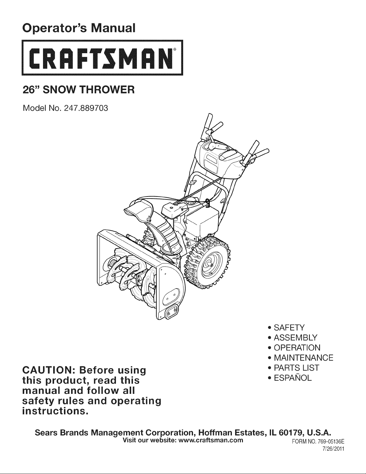
Operator's Manual
CRRFTSMRH
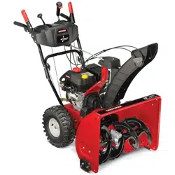
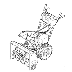
26" SNOW THROWER
Model No. 247.889703
CAUTION: Before using
this product, read this
manual and follow all
safety rules and operating
instructions.
o SAFETY
ASSEMBLY
OPERATION
MAINTENANCE
PARTS LIST
o ESPANOL
Sears Brands Management Corporation, Hoffman Estates, IL 60179, U.S.A.
Visit our website: www.craftsman.com FORMNO.769-05136E
7/26/2011
WarrantyStatement.................... Page2
SafeOperationPractices.............. Pages3-6
Assembly......................... Pages8-13
Operation........................ Pages14-17
Service&Maintenance.............. Pages18-25
Off-SeasonStorage................... Page26
Troubleshooting...................... Page27
PartsList......................... Pages28-45
RepairProtectionAgreement............ Page49
Espadol............................. Page50
CRAFTSMANTWOYEARFULL WARRANTY
FORTWOYEARSfromthedateofpurchase,thisproductiswarrantedagainstanydefectsinmaterialorworkmanship.Defectiveproductwill
receivefreerepairorfreereplacementifrepairisunavailable.
Thiswarrantyisvoidifthisproductiseverusedwhileprovidingcommercialservicesorifrentedtoanotherperson.
Forwarrantycoverage details to obtain repairor replacement,visit the website: www.craftsman.com
This warranty covers ONLYdefects in material and workmanship. Warranty coverage does NOTinclude:
• Expendableitemsthatcan wearoutfromnormalusewithinthewarrantyperiod,includingbut not limitedto augers,augerpaddles,drift
cutters,skidshoes,shaveplate,shearpins, spark plug,air cleaner,belts,and oil filter.
• Standardmaintenanceservicing,oilchanges,or tune-ups.
• Tire replacementor repaircausedby puncturesfrom outsideobjects,such as nails,thorns,stumps,or glass.
Tireor wheelreplacementor repairresultingfromnormalwear,accident,or improperoperationor maintenance.
Repairsnecessarybecauseof operatorabuse, includingbutnot limitedto damagecausedby over-speedingthe engine,or fromimpacting
objectsthat bendthe frame,augershaft,etc.
• Repairsnecessarybecauseof operatornegligence,includingbut not limitedto,electricalandmechanicaldamagecausedby improper
storage,failureto usethe propergradeandamountof engineoil, or failureto maintainthe equipmentaccordingto the instructionscontained
inthe operator'smanual.
• Engine(fuelsystem)cleaningor repairscausedbyfuel determinedto becontaminatedor oxidized(stale).In general,fuel shouldbeused
within30 daysof itspurchasedate.
Normaldeteriorationandwearof the exteriorfinishes,or productlabelreplacement.
Thiswarrantygivesyou specificlegalrights,andyou mayalso haveotherrightswhichvaryfromstateto state.
Sears Brands Management Corporation, Hoffman Estates, IL 60179
EngineOilType: 5W-30
EngineOilCapacity: 20ounces
FuelCapacity: 2.3Quarts
SparkPlug: F6RTC
SparkPlugGap: .020"to .030"
Model Number.................................................................
Serial Number .................................................................
Dateof Purchase.............................................................
Recordthe modelnumber,serialnumber
anddateof purchaseabove
© KCD IR LLC
2
Thissymbolpointsout importantsafetyinstructionswhich,if not
followed,couldendangerthepersonalsafetyand/orpropertyof
yourselfand others. Readandfollowall instructionsin thismanual
beforeattemptingto operatethismachine.Failureto complywith
theseinstructionsmay resultin personalinjury.Whenyou seethis
symbol,HEEDITSWARNING!
CALIFORNIA PROPOSITION 65
EngineExhaust,someof itsconstituents,andcertainvehicle
componentscontainoremitchemicalsknownto Stateof California
to cause cancerand birthdefectsorotherreproductiveharm,
Thismachinewasbuiltto beoperatedaccordingto the safeopera-
tion practicesin this manual.As with anytypeof powerequipment,
carelessnessor error on the partof the operatorcan resultin serious
injury.Thismachineis capableof amputatingfingers,hands,toes
andfeetandthrowingdebris.Failureto observethe followingsafety
instructionscouldresultin seriousinjuryor death.
Your Responsibility--Restrict the use of thispowermachineto
personswho read,understandand followthewarningsand instruc-
tionsin thismanualandon the machine,
SAVE THESE INSTRUCTIONS!
TRAiNiNG
• Read,understand,and followall instructionson the machineand
in themanual(s)beforeattemptingto assembleandoperate.
Failureto do socan resultinseriousinjuryto the operatorand/
orbystanders.Keepthismanualin a safeplaceforfutureand
regularreferenceandfor orderingreplacementparts.
• Befamiliarwithall controlsandtheir properoperation.Knowhow
to stop the machineanddisengagethemquickly.
• Neverallowchildrenunder 14yearsof age to operatethis
machine.Children14andover shouldreadandunderstandthe
instructionsand safe operationpracticesin thismanualand on
the machineand be trainedand supervisedby anadult.
Neverallowadultsto operatethis machinewithoutproper
instruction.
• Thrownobjectscan causeseriouspersonalinjury.Planyour
snow-throwingpatternto avoiddischargeof materialtoward
roads,bystandersandthe like.
Keepbystanders,pets andchildrenat least75 feet from the
machinewhile it is in operation.Stopmachineif anyoneenters
the area.
• Exercisecautionto avoidslippingor falling,especiallywhen
operatingin reverse.
PREPARATION
Thoroughlyinspectthearea wherethe equipmentisto beused.
Removeall doormats,newspapers,sleds,boards,wiresandother
foreignobjects,whichcouldbe trippedoverorthrownby the auger/
impeller.
• Alwayswear safetyglassesor eyeshieldsduringoperationand
while performingan adjustmentor repairto protectyoureyes.
Thrownobjectswhichricochetcancauseseriousinjuryto the
eyes.
Donot operatewithoutwearingadequatewinteroutergarments.
Donot wearjewelry,longscarvesor otherlooseclothing,which
could becomeentangledin movingparts.Wearfootwearwhich
will improvefooting on slipperysurfaces.
Usea groundedthree-wireextensioncordand receptaclefor all
machineswith electricstartengines.
Disengageall controlleversbeforestartingthe engine.
Adjustcollectorhousingheightto cleargravelorcrushedrock
surfaces.
• Neverattemptto makeanyadjustmentswhileengineis running,
exceptwherespecificallyrecommendedinthe operator'smanual.
Letengineandmachineadjustto outdoortemperaturebefore
startingto clearsnow.
3
Safe Handling of Gasoline
Toavoidpersonalinjuryor propertydamageuseextremecare in
handlinggasoline.Gasolineis extremelyflammableand the vaporsare
explosive.Seriouspersonalinjurycan occurwhengasolineis spilled
onyourselfor yourclotheswhichcan ignite.Washyour skinand
changeclothesimmediately.
• Useonly anapprovedgasolinecontainer.
• Extinguishall cigarettes,cigars,pipesandother sources
of ignition.
• Neverfuelmachineindoors.
• Neverremovegas capor addfuel whilethe engineis hot
or running.
• Allowengineto coolat leasttwo minutesbeforerefueling.
• Neveroverfill fueltank. Filltank to no morethan1/2inch
belowbottomof filler neckto providespacefor fuel
expansion.
• Replacegasolinecap and tightensecurely.
• If gasolineis spilled,wipeit offthe engineandequipment.
Movemachineto anotherarea.Wait5 minutesbefore
startingthe engine.
• Neverstorethe machineor fuel containerinsidewhere
thereis an open flame,sparkor pilotlight (e.g.furnace,
waterheater,spaceheater,clothesdryer etc.).
• Allowmachineto cool at least5 minutesbeforestoring.
• Neverfill containersinsidea vehicleor ona truckor trailer
bedwith a plasticliner.Alwaysplacecontainerson the
groundawayfromyourvehiclebeforefilling.
• If possible,removegas-poweredequipmentfrom thetruck
ortrailerand refuelit on the ground.If thisis not possible,
then refuelsuchequipmenton a trailerwitha portable
container,ratherthan from a gasolinedispensernozzle.
• Keepthe nozzleincontactwith the rimof the fueltank or
containeropeningat all timesuntil fuelingis complete.Do
notuse a nozzlelock-opendevice.
OPERATION
• Do not puthandsorfeet near rotatingparts,in the auger/impeller
housingor chuteassembly.Contactwith the rotatingpartscan
amputatehandsandfeet.
• Theauger/impellercontrolleveris a safetydevice.Neverbypass
itsoperation.Doingso makesthe machineunsafeandmay cause
personalinjury.
• Thecontrolleversmustoperateeasilyin bothdirectionsand
automaticallyreturnto the disengagedpositionwhenreleased.
• Neveroperatewith a missingor damagedchuteassembly.Keep
all safetydevicesin placeandworking.
• Neverrunan engine indoorsor ina poorlyventilatedarea. Engine
exhaustcontainscarbonmonoxide,anodorlessanddeadlygas.
• Do notoperatemachinewhileunder the influenceof alcoholor
drugs.
• Mufflerand enginebecomehotandcan causea burn.Do not
touch.Keepchildrenaway.
• Exerciseextremecautionwhenoperatingon orcrossinggravel
surfaces.Stay alertfor hiddenhazardsor traffic.
• Exercisecautionwhenchangingdirectionand whileoperatingon
slopes.Do notoperateon steepslopes.
• Planyoursnow-throwingpatternto avoiddischargetowards
windows,walls,carsetc. Thus,avoidingpossibleproperty
damageor personalinjurycausedby a ricochet.
• Neverdirect dischargeat children,bystandersand petsor allow
anyoneinfront of the machine.
• Donot overloadmachinecapacityby attemptingto clearsnowat
too fastof a rate.
• Neveroperatethis machinewithoutgoodvisibility or light. Always
be sureof yourfootingand keepa firmholdon the handles.Walk,
neverrun.
• Disengagepowerto theauger/impellerwhentransportingor not
in use.
• Neveroperatemachineat hightransportspeedson slippery
surfaces.Lookdownand behindand usecare whenbackingup.
• If the machineshouldstart to vibrateabnormally,stopthe engine,
disconnectthe spark plugwire andgroundit againstthe engine.
Inspectthoroughlyfor damage.Repairanydamagebefore
startingandoperating.
• Disengageall controlleversandstop enginebeforeyouleave
the operatingposition(behindthe handles).Waituntilthe auger/
impellercomesto a completestopbeforeuncloggingthechute
assembly,makingany adjustments,or inspections.
• Neverput yourhandin the dischargeor collectoropenings.Do
not unclogchuteassemblywhileengineis running.Shutoff
engineand remainbehindhandlesuntilall movingparts have
stoppedbeforeunclogging.
• Useonly attachmentsandaccessoriesapprovedby the manufac-
turer (e.g.wheelweights,tire chains,cabsetc.).
• Whenstartingengine,pull cord slowlyuntilresistanceis felt, then
pull rapidly.Rapidretractionof startercord(kickback)will pull
handand armtowardenginefasterthan youcan let go. Broken
bones,fractures,bruisesor sprainscould result.
• If situationsoccur whichare notcoveredinthis manual,use care
andgood judgment.
• Forin-warrantysafety,operationor maintenancequestions,or to
orderparts and scheduleservice,call 1-800-4-MY-HOME.
CLEARING A CLOGGED DISCHARGE CHUTE
Handcontactwith the rotatingimpellerinsidethe dischargechute
is the mostcommoncauseof injuryassociatedwith snowthrowers.
Neveruse yourhand to cleanout thedischargechute.
Toclear thechute:
1. SHUTTHEENGINEOFF!
2. Wait 10secondsto be surethe impellerbladeshavestopped
rotating.
3. Alwaysusea clean-outtool,not yourhands.
4
MAINTENANCE & STORAGE
• Nevertamperwithsafetydevices.Checktheirproperoperation
regularly.Referto the maintenanceand adjustmentsectionsof
thismanual.
• Beforecleaning,repairing,or inspectingmachinedisengageall
controlleversandstop the engine.Wait untilthe auger/impeller
cometo a completestop.Disconnectthe sparkplugwireand
groundagainsttheengineto preventunintendedstarting.
Checkboltsand screwsfor propertightnessat frequentintervals
to keepthe machineinsafe workingcondition.Also,visually
inspectmachinefor anydamage.
Do notchangetheenginegovernorsettingor over-speedthe
engine.Thegovernorcontrolsthe maximumsafeoperatingspeed
of the engine.
Snowthrowershaveplatesand skidshoesaresubjectto wear
anddamage.Foryoursafetyprotection,frequentlycheckall
componentsand replacewithoriginalequipmentmanufacturer's
(OEM)partsonlyas listedinthe Partspagesof thisoperator's
manual.Useof parts which donot meetthe originalequipment
specificationsmayleadto improperperformanceand compro-
misesafety!
Checkcontrolleversperiodicallyto verifythey engageanddisen-
gageproperlyandadjust,if necessary.Referto the adjustment
sectioninthisoperator'smanualfor instructions.
Maintainor replacesafetyandinstructionlabels,as necessary.
Observeproperdisposallawsand regulationsfor gas,oil,etc. to
protectthe environment.
Priorto storing,run machinea few minutestoclear snowfrom
machineand preventfreezeup of auger/impeller.
Neverstorethe machineor fuel containerinsidewherethereisan
openflame,sparkorpilot lightsuchas a waterheater,furnace,
clothesdryer etc.
Alwaysreferto the operator'smanualfor properinstructionson
off-seasonstorage.
Checkfuelline,tank, cap,andfittingsfrequentlyfor cracksor
leaks.Replaceif necessary.
Do notcrank enginewithsparkplugremoved.
Accordingto the ConsumerProductsSafetyCommission(CPSC)
andthe U.S.EnvironmentalProtectionAgency(EPA),this product
hasan AverageUsefulLifeof seven(7) years,or 60 hoursof
operation.At the endof theAverageUsefulLifehavethe machine
inspectedannuallybyan authorizedservicedealerto ensurethat
allmechanicalandsafetysystemsareworkingproperlyand not
wornexcessively.Failureto do so can resultinaccidents,injuries
ordeath.
DO NOT MODIFY ENGINE
Toavoidseriousinjuryor death,do not modifyengineinany way.
Tamperingwiththe governorsettingcanlead to a runawayengineand
causeit to operateat unsafespeeds.Nevertamperwithfactorysetting
of engine governor.
NOTICE REGARDING EMiSSiONS
Engineswhich are certifiedtocomplywithCaliforniaandfederal
EPAemissionregulationsfor SORE(SmallOff RoadEquipment)are
certifiedto operateon regularunleadedgasoline,and mayinclude
the followingemissioncontrolsystems:EngineModification(EM),
OxidizingCatalyst(OC), SecondaryAir Injection(SAI)and ThreeWay
Catalyst(TWO)if so equipped.
SPARK ARRESTOR
Thismachineisequippedwith an internalcombustionengineand
shouldnotbe usedonor nearany unimprovedforest-covered,
brush-coveredor grass-coveredland unlessthe engine'sexhaust
systemisequippedwith a sparkarrestormeetingapplicablelocalor
statelaws(if any)
Ifa sparkarrestoris used, it shouldbe maintainedin effectiveworking
orderby theoperator.Inthe State of Californiathe aboveis required
bylaw (Section4442 of the CaliforniaPublicResourcesCode).Other
statesmayhavesimilarlaws. Federallawsapplyonfederallands.
A sparkarrestorfor the muffleris availablethroughyournearestSears
PartsandRepairServiceCenter.
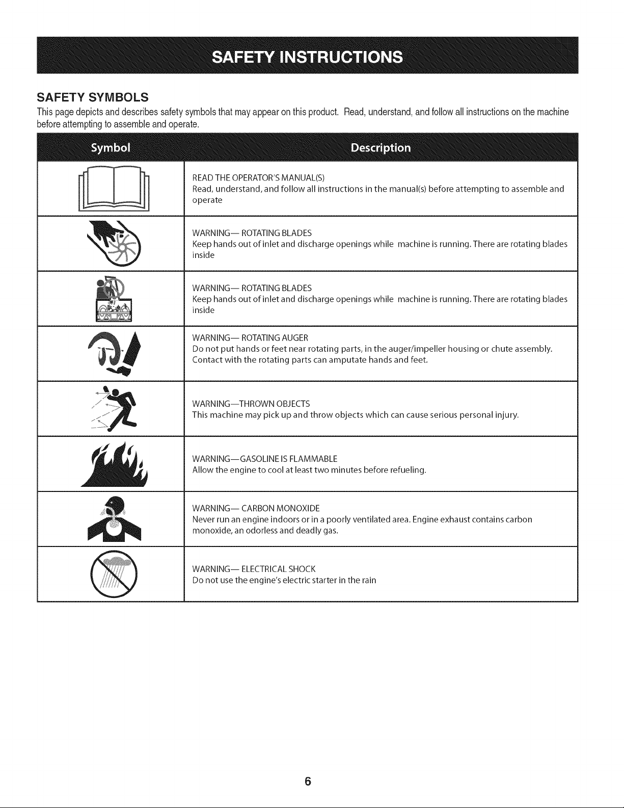
SAFETY SYMBOLS
Thispagedepictsand describessafetysymbolsthatmayappear on thisproduct. Read,understand,and followall instructionson the machine
beforeattemptingto assembleandoperate.
. +
i
i
"JIp
READ THE OPERATOR'S MANUAL(S)
Read, understand, and follow all instructions in the manual(s) before attempting to assemble and
operate
WARNING-- ROTATING BLADES
Keep hands out of inlet and discharge openings while machine is running. There are rotating blades
inside
WARNING-- ROTATING BLADES
Keep hands out of inlet and discharge openings while machine is running. There are rotating blades
inside
WARNING-- ROTATING AUGER
Do not put hands or feet near rotating parts, in the auger/impeller housing or chute assembly.
Contact with the rotating parts can amputate hands and feet.
WARNING--THROWN OBJECTS
This machine may pick up and throw objects which can cause serious personal injury.
WARNING--GASOLINE IS FLAMMABLE
Allow the engine to cool at least two minutes before refueling.
WARNING-- CARBON MONOXIDE
Never run an engine indoors or in a poorly ventilated area. Engine exhaust contains carbon
monoxide, an odorless and deadly gas+
WARNING-- ELECTRICAL SHOCK
Do not use the engine's electric starter in the rain
6

Thispageleftintentionallyblank.
7
NOTE:Referencesto rightorleft sideof the snowthrowerare
determinedfrombehindthe unit in the operatingposition(standing
directlybehindthe snow thrower,facingthe handlepanel).
REMOVING FROM CARTON
1. Cut the cornersof thecartonandlay the sidesflaton the ground.
Removeand discard allpackinginserts.
2. Movethe snowthrowerout of thecarton.
3. Makecertainthe cartonhas beencompletelyemptiedbefore
discardingit.
ASSEMBLY
1. Observethe lowerreararea of the snowthrowerto besure both
cablesarealignedwith rollerguidesbeforepivotingthe handle
upward.
a. Placethe shiftleverin the F6position.
b. Pull up andbackon upperhandleas shownin Figure1.As
youare raisingthe handleupward,make surethat bothends
of the centercablearepositionedproperlyinthe brackets.
Alignupperhandlewith the lowerhandle.
c. Tightenhandknobssecuringupperhandleto lowerhandle.
Removeand discard any rubberbands,if present.Theyare
for packagingpurposesonly.
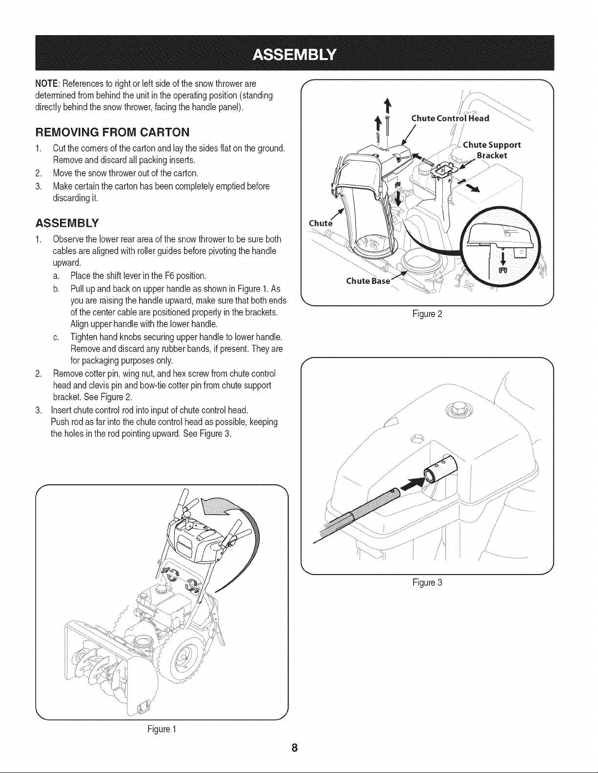
2. Removecotterpin,wing nut, andhexscrewfromchutecontrol
headand clevispin and bow-tiecotterpinfromchutesupport
bracket.SeeFigure2.
3. Insertchutecontrol rod intoinputof chutecontrolhead.
Pushrodas far intothe chutecontrolheadas possible,keeping
the holesin the rod pointingupward.SeeFigure3.
I
Chute Control Head
_ort
Bracket
Figure2
f
Figure3
J
J
Figure1
8
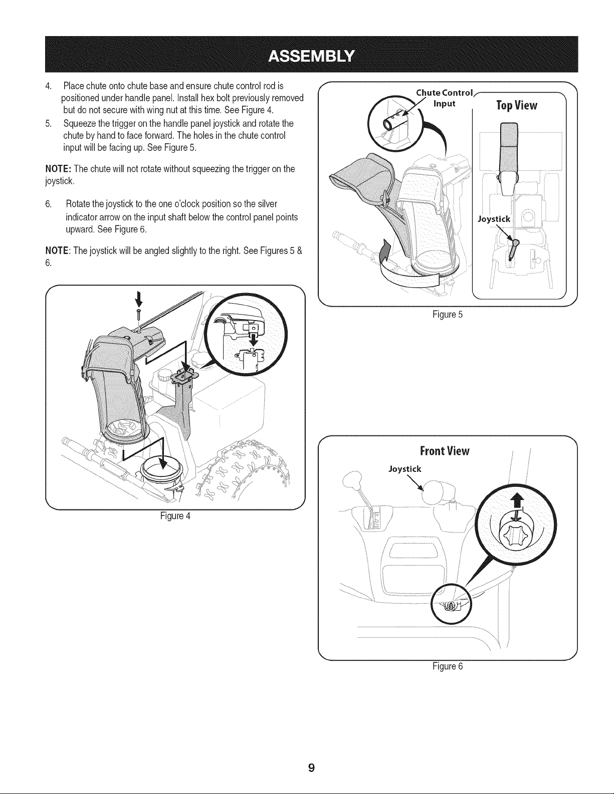
4. Placechuteontochutebaseandensurechutecontrolrod is
positionedunderhandlepanel.Installhex boltpreviouslyremoved
but do notsecurewithwing nutat this time.See Figure4.
5. Squeezethetriggeron the handlepaneljoystickand rotatethe
chutebyhand to faceforward.The holesin the chutecontrol
inputwill be facing up. SeeFigure5.
NOTE:The chutewill not rotatewithoutsqueezingthe triggeronthe
joystick.
6. Rotatethejoystickto the oneo'clockpositionso the silver
indicatorarrowonthe inputshaft belowthe controlpanel points
upward.SeeFigure6.
NOTE:Thejoystickwillbe angledslightlyto the right.SeeFigures5 &
6.
Figure4
f
Chute Controlf
Figure5
f
FroatView
Joystick
Figure6
J
9
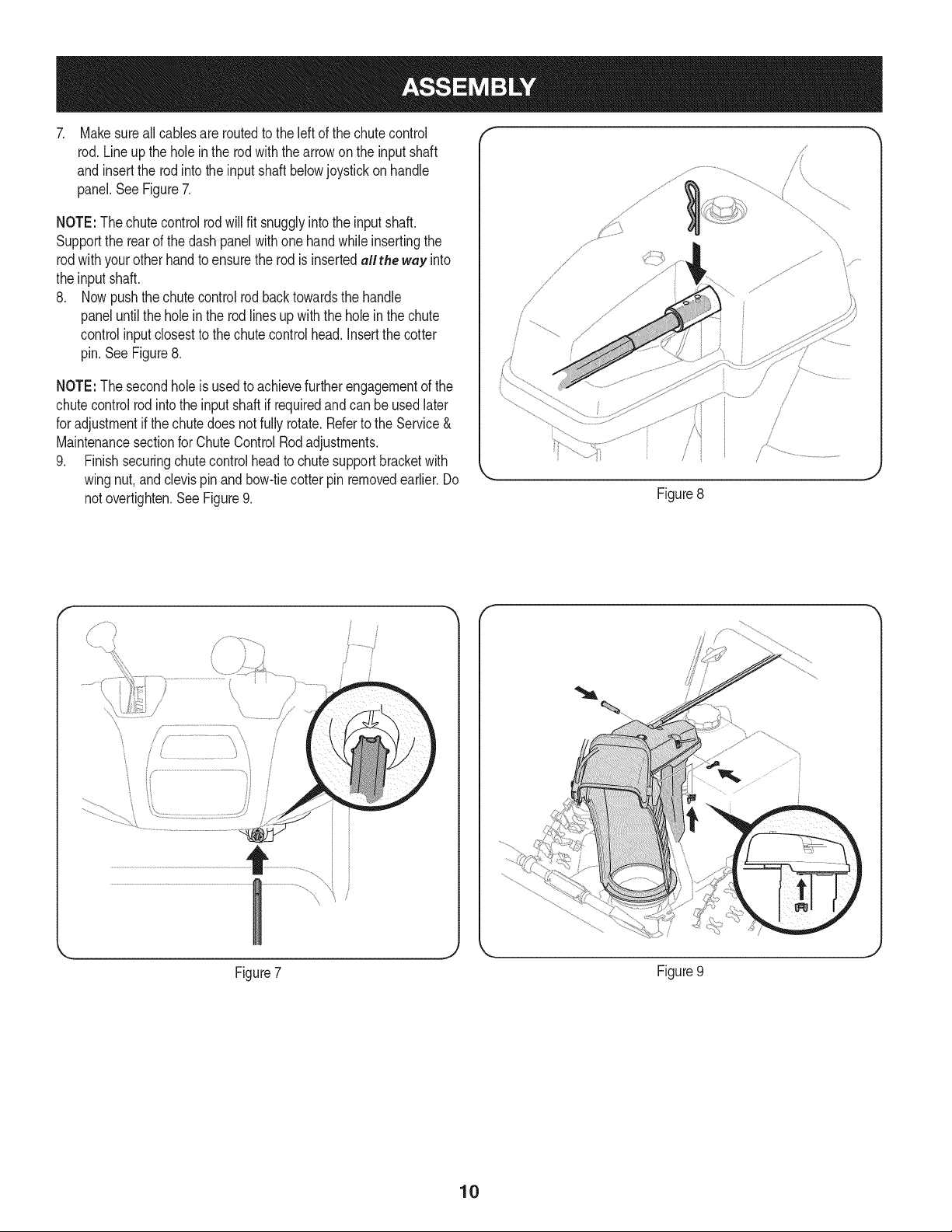
Makesureall cablesare routedto the leftof the chute control
rod.Lineup the holein the rod with thearrowon the inputshaft
and insertthe rodinto the inputshaftbelowjoystickon handle
panel.See Figure7.
NOTE:The chutecontrol rodwill fit snugglyintothe inputshaft.
Supportthe rearof the dashpanelwithone handwhile insertingthe
rodwith yourother handto ensurethe rodisinsertedallthe wey into
the inputshaft.
8. Now pushthechutecontrolrodbacktowardsthe handle
paneluntil the holein the rodlines upwiththe hole in the chute
controlinputclosestto the chutecontrolhead.Insertthecotter
pin.See Figure8.
NOTE:The secondhole is usedto achievefurtherengagementof the
chutecontrolrod intothe inputshaft if requiredandcan be usedlater
for adjustmentif thechute doesnot fullyrotate.Referto the Service&
Maintenancesectionfor ChuteControl Rodadjustments.
9. Finishsecuringchutecontrol headto chutesupportbracketwith
wingnut,and clevispin andbow-tiecotter pinremovedearlier.Do
not overtighten.See Figure9.
/i _
Figure8
\
\,
y..................
Figure7
Figure9
10
M
,iiiiiii!,! ii_ili
iiii 1
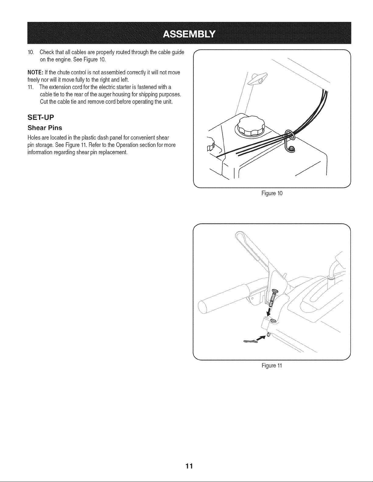
10. Checkthat allcablesareproperlyroutedthroughthecable guide
on theengine.SeeFigure10.
NOTE: if the chutecontrol is notassembledcorrectlyit will not move
freelynorwill it movefullyto the rightandleft.
11. Theextensioncord forthe electricstarteris fastenedwitha
cabletie to the rearof the augerhousingfor shippingpurposes.
Cutthe cabletie and removecord beforeoperatingthe unit.
SET-UP
Shear Pins
Holesare locatedinthe plasticdashpanelfor convenientshear
pinstorage.See Figure11.Referto the Operationsectionfor more
informationregardingshearpin replacement.
/
/
i I
/
Figure10
Figure11
J
11
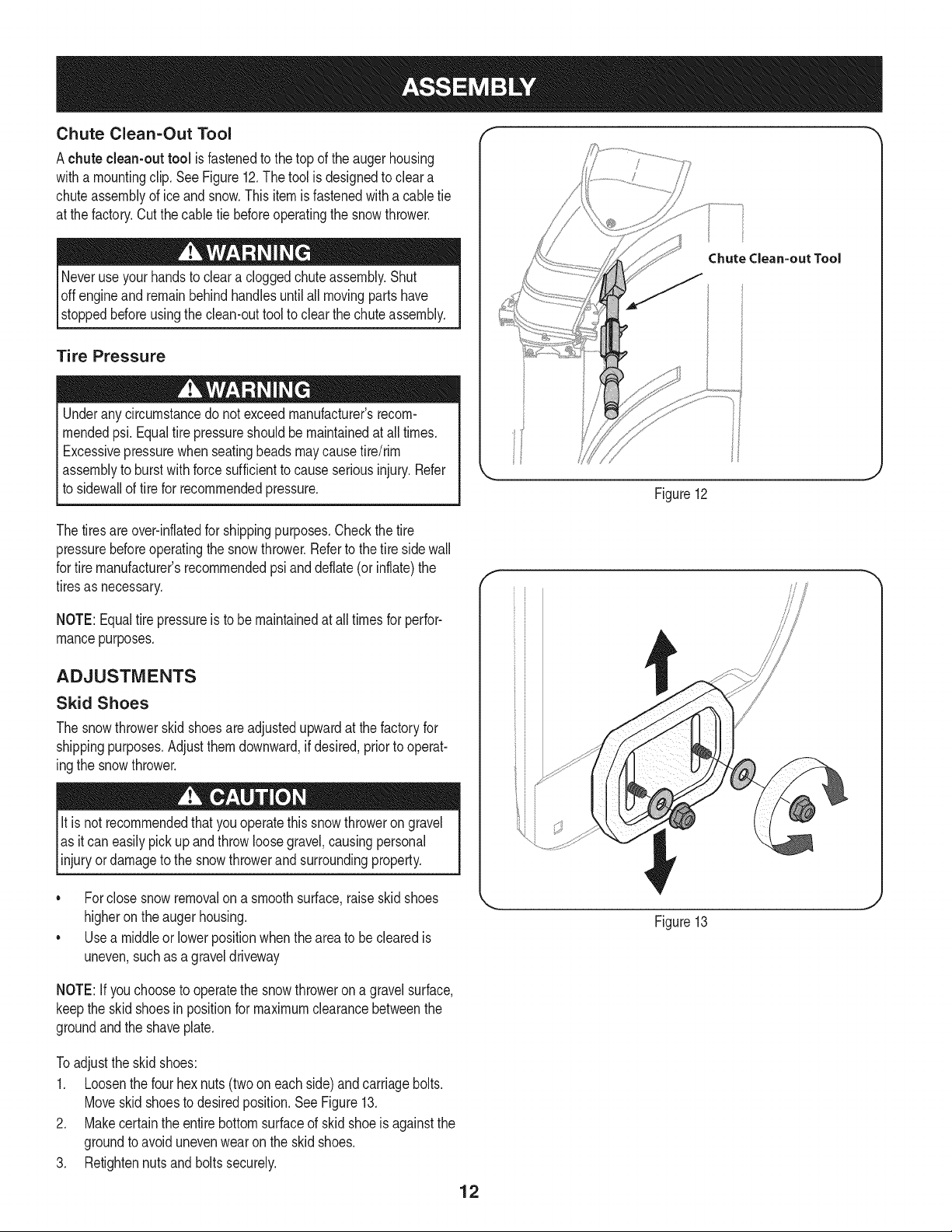
Chute Clean=Out Tool
Achute clean-out tool is fastenedto the top of the augerhousing
witha mountingclip.SeeFigure12.The tool is designedto cleara
chuteassemblyof ice andsnow.Thisitemis fastenedwith a cabletie
at the factory.Cut thecable tie beforeoperatingthe snowthrower.
loff ving partshave
stoppedbeforeusingthe clean-outtool to clear thechuteassembly.
Tire Pressure
Underanycircumstancedo notexceedmanufacturer'srecom-
mendedpsi. Equaltire pressureshouldbe maintainedat all times.
Excessivepressurewhenseatingbeadsmaycausetire/rim
assemblyto burst with forcesufficientto causeseriousinjury.Refer
to sidewallof tirefor recommendedpressure.
Chute Clean=out Tool
Figure12
Thetiresare over-inflatedfor shippingpurposes.Checkthetire
pressurebeforeoperatingthe snowthrower.Referto the tire sidewall
for tiremanufacturer'srecommendedpsianddeflate(or inflate)the
tiresas necessary.
NOTE:Equaltire pressureis to be maintainedat alltimesfor perfor-
mancepurposes.
ADJUSTMENTS
Skid Shoes
The snowthrowerskid shoesare adjustedupwardat thefactory for
shippingpurposes.Adjustthemdownward,if desired,priorto operat-
ingthe snowthrower.
It is not recommendedthatyouoperatethis snowthrowerongravel
as it can easilypick up andthrowloosegravel,causingpersonal
njuryordamageto the snowthrowerand surroundng property.
• Forclosesnow removalon a smoothsurface,raiseskidshoes
higheronthe augerhousing.
• Usea middleor lowerpositionwhentheareato be clearedis
uneven,suchas a graveldriveway
Figure13
NOTE:If youchooseto operatethe snowthrowerona gravelsurface,
keepthe skid shoesin positionfor maximumclearancebetweenthe
groundandthe shaveplate.
Toadjustthe skid shoes:
1. Loosenthe four hexnuts(two on each side)andcarriagebolts.
Moveskidshoesto desiredposition.See Figure13.
2. Makecertainthe entirebottomsurfaceof skidshoeis againstthe
groundto avoidunevenwearonthe skidshoes.
3. Retightennutsand boltssecurely.
12
Auger Control
Priorto operatingyoursnowthrower,carefullyreadand followall
instructionsbelow.Performall adjustmentsto verifyyoursnow
throweris operatingsafelyandproperly.
Checktheadjustmentof the augercontrolas follows:
1. Whentheaugercontrolis releasedand in the disengaged"up"
position,the cableshouldhavevery littleslack. It shouldNOTbe
tight.
2. In a well-ventilatedarea,start the snowthrowerengine.Refer
to Startingthe Engineinthe Operationsection.Makesurethe
throttleis set in the FASTposition.
3. Whilestandingin the operator'sposition(behindthe snow
thrower),engagethe augers.
4. Allowtheaugersto remainengagedfor approximatelyten (10)
secondsbeforereleasingthe augercontrol.Repeatthisseveral
times.
5. With theauger controlin thedisengaged"up" position,walkto the
frontof the machine.
6. Confirmthatthe augershavecompletelystoppedrotatingand
showNOsignsof motion.If anyaugershowsANY signof
rotating,immediatelyreturnto the operator'spositionand shutoff
the engine.Waitfor ALL movingpartsto stopbeforeadjustingthe
augercontrol.
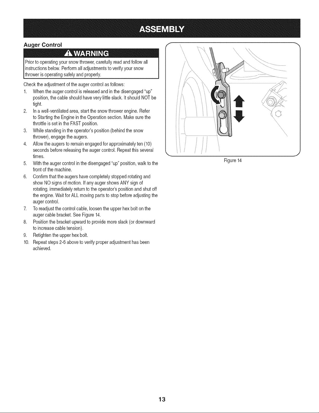
7. Toreadjustthecontrolcable, loosentheupperhexbolt on the
augercablebracket.SeeFigure14.
8. Positionthe bracketupwardto providemoreslack(or downward
to increasecabletension).
9. Retightenthe upperhex bolt.
10. Repeatsteps2-6 aboveto verifyproperadjustmenthasbeen
achieved.
Figure14
\
\
\
\
\
\
13
f
Drive Control
Shift Lever
/ Four=Way Chute Control" (Joystick)
J
Auger Control
Chute Assembly
Gas Cap
Clean Out
Tool
\
\
Augers
Skid Shoe
Mumer Recoil Starter
\ Handle
Primer ___. FUEL LEVEL
\
\
Key
Throttle
Control
Choke
Control
/
Oil Drain
Electric Starter
Button
Electric Starter Outlet
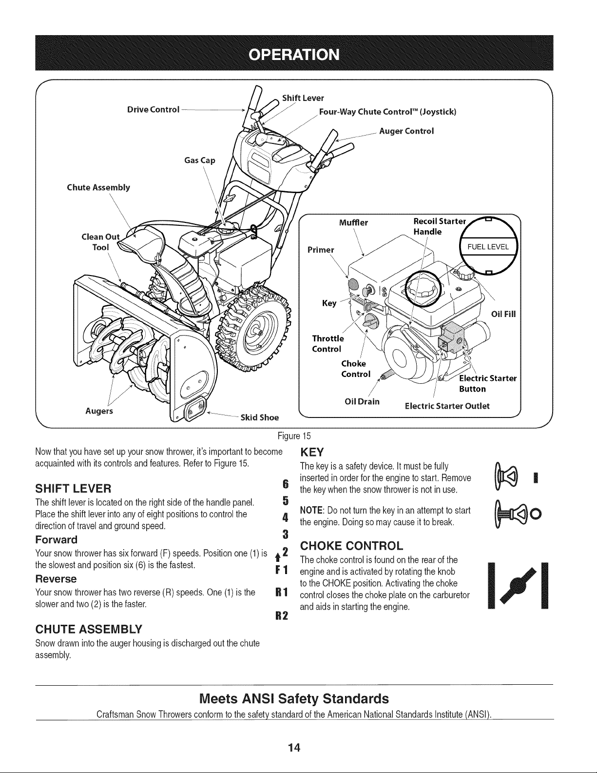
Figure15
Nowthat youhavesetup yoursnowthrower,it's importantto become
acquaintedwith itscontrolsand features.Referto Figure15.
SHIFT LEVER 6
The shiftleveris locatedonthe rightsideof the handle panel. 5
Placethe shiftleverinto anyof eightpositionsto controlthe 4
directionof travel and groundspeed.
Forward 3
Yoursnowthrowerhas six forward(F) speeds.Positionone(1)is t 2
the slowestand positionsix (6) is the fastest. F 1
Reverse
Yoursnowthrowerhastwo reverse(R) speeds.One(1) is the
slowerandtwo (2) is the faster.
CHUTE ASSEMBLY
Snowdrawnintothe augerhousingis dischargedout the chute
assembly.
KEY
The key is a safetydevice.It mustbe fully
insertedinorderfor the engineto start, Remove
the key whenthe snowthroweris not in use,
NOTE: Donot turnthe key in an attemptto start
the engine.Doingso may causeit to break.
CHOKE CONTROL
The chokecontrolis foundon the rearof the
engineand is activatedby rotatingthe knob
to the CHOKEposition.Activatingthe choke
controlclosesthe chokeplateon the carburetor
andaids in startingthe engine.
,J
Meets ANSi Safety Standards
CraftsmanSnowThrowersconformto the safetystandardof the AmericanNationalStandardsInstitute(ANSi).
14
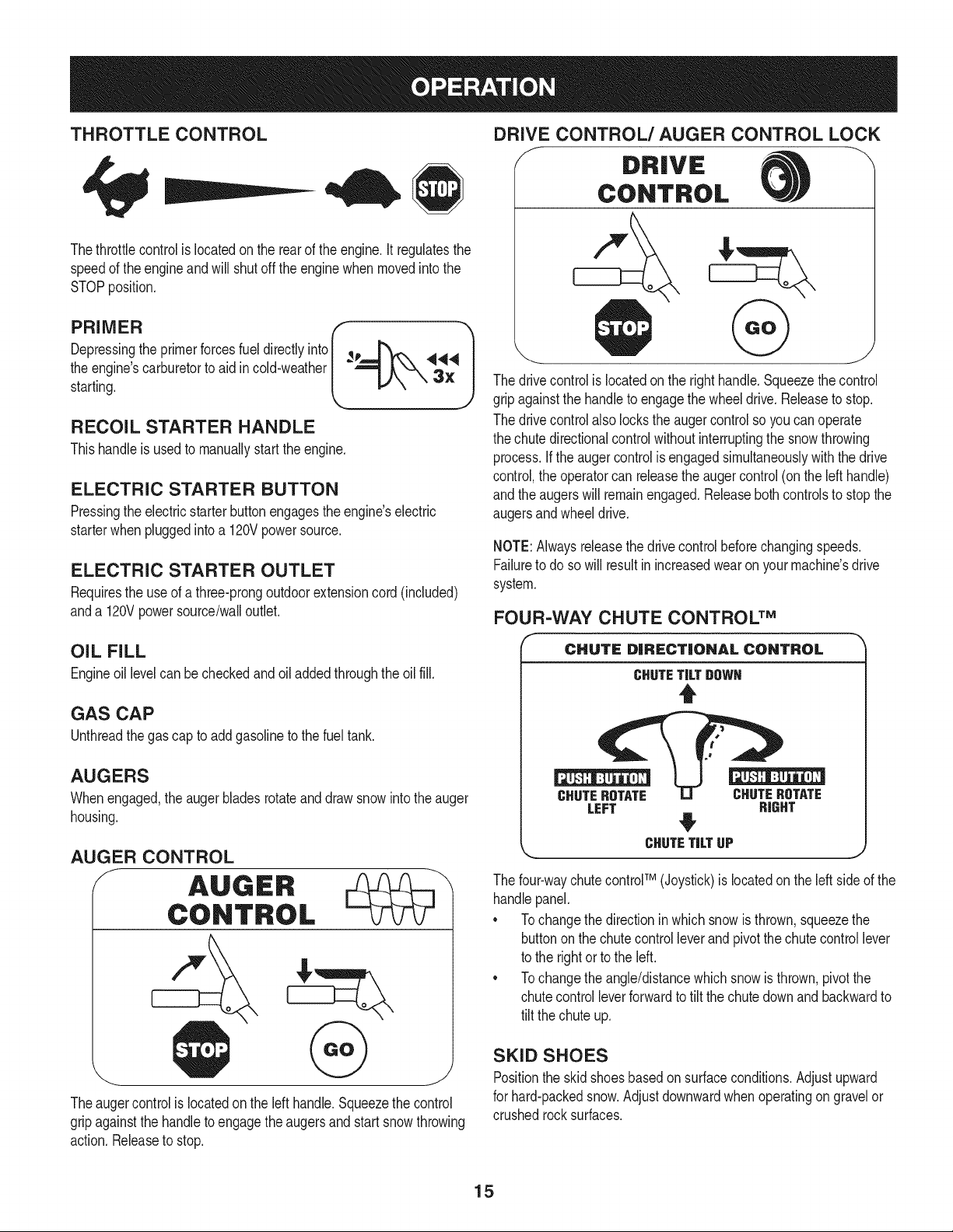
THROTTLE CONTROL
Thethrottlecontrolis locatedon the rearof the engine.It regulatesthe
speedof theengine andwill shutoff the enginewhenmovedintothe
STOPposition.
Depressingthe primerforcesfuel directlyinto _p
the engine'scarburetorto aid incold-weather
starting.
RECOIL STARTER HANDLE
Thishandleis usedto manuallystartthe engine.
ELECTRIC STARTER BUTTON
Pressingthe electricstarterbuttonengagesthe engine'selectric
starterwhenpluggedintoa 120Vpowersource.
ELECTRIC STARTER OUTLET
Requiresthe useof a three-prongoutdoorextensioncord(included)
anda 120Vpowersource/walloutlet.
OIL FILL
Engineoil levelcan be checkedand oiladdedthroughtheoil fill.
GAS CAP
Unthreadthe gascap to add gasolineto the fuel tank.
AUGERS
Whenengaged,the augerbladesrotateand drawsnowintothe auger
housing.
AUGER CONTROL
f AUGER
CONTROL
Theaugercontrolis locatedonthe left handle.Squeezethecontrol
gripagainstthe handleto engagetheaugersand start snowthrowing
action.Releaseto stop.
DRIVE CONTROL/AUGER CONTROL LOCK
f DRIVE
CONTROL
@
The drivecontrolis locatedon the righthandle.Squeezethe control
gripagainstthe handleto engagethe wheeldrive.Releaseto stop.
The drivecontrolalso lockstheaugercontrolso youcan operate
the chute directionalcontrolwithoutinterruptingthe snowthrowing
process.If the augercontrolis engagedsimultaneouslywiththe drive
control,the operatorcan releasethe augercontrol (onthe left handle)
andthe augerswill remainengaged.Releaseboth controlsto stopthe
augersandwheeldrive.
NOTE:Alwaysreleasethedrivecontrolbeforechangingspeeds.
Failureto do so will result in increasedwearon yourmachine'sdrive
system.
FOUR-WAY CHUTE CONTROL TM
f
CHUTE DiRECTiONAL CONTROL
CHUTETiLTDOWH
t
CHUTEROTATE CHUTEROTATE
LEFT RIGHT
CHUTETiLTUP
The four-waychutecontroFM(Joystick)is locatedon theleft sideof the
handlepanel.
* Tochangethe directioninwhichsnowis thrown,squeezethe
buttononthe chutecontrolleverand pivotthe chutecontrollever
to the rightor to the left.
* Tochangethe angle/distancewhichsnowisthrown,pivotthe
chutecontrolleverforwardto tiltthe chute downand backwardto
tilt the chuteup.
SKID SHOES
Positionthe skid shoesbasedonsurfaceconditions.Adjustupward
for hard-packedsnow.Adjustdownwardwhenoperatingon gravelor
crushedrocksurfaces.
15
CLEAN-OUT TOOL
Neveruse yourhandsto cleara cloggedchuteassembly.Shut
off engineandremainbehindhandlesuntilall movingpartshave
stoppedbeforeusingthe clean-outtoolto clear thechuteassembly.
Thechuteclean-outtool is convenientlyfastenedto the rearof the
augerhousingwith a mountingclip. Shouldsnowandice become
lodgedin thechuteassemblyduringoperation,proceedas followsto
safelycleanthechuteassemblyand chute opening:
1. Releaseboththe AugerControlandthe DriveControl.
2. Stopthe engineby removingthe ignitionkey.
3. Removethe clean-outtoolfrom the clip whichsecuresit to the
rearof the augerhousing.
4. Use the shovel-shapedend of theclean-outtool to dislodgeand
scoopany snowand icewhichhasformedin andnearthechute
assembly.
5. Refastenthe clean-outtool to the mountingclip onthe rearof
theaugerhousing,reinsertthe ignitionkeyand startthe snow
thrower'sengine.
6. Whilestandingin the operator'sposition(behindthesnow
thrower),engagethe augercontrolfora fewsecondsto clear any
remainingsnowand ice fromthechute assembly.
BEFORE STARTING ENGINE
Read,understand,and followall instructionsand warningson the
machineand inthismanualbeforeoperating.
Oil
Theunit was shippedwith oil inthe engine.Checkoil levelbefore
eachoperationto ensureadequateoil inthe engine.Forfurther
instructions,refertothe stepson page18.
NOTE:Besureto checkthe engineon a levelsurfacewiththe engine
stopped.
1. Removethe oil fillercap/dipstickandwipethe dipstickclean.
2. insertthe cap/dipstickintothe oil filler neck,andtightenthe cap
until seated.
3. Removethe oil fillercap/dipstick,ifthe levelislow,slowlyadd
oil (5%30, witha minimumclassificationof SF/SG)untiloil level
registersbetweenhigh (H) andlow(L).
NOTE:Do notoverfill.Overfillingwith oil mayresultinenginesmoking,
hardstartingor sparkplugfouling.
4. Replaceand tighten cap/dipstickfirmlybeforestartingengine.
Gasoline
Useautomotivegasoline(unleadedor low leadedto minimizecombus-
tionchamberdeposits)with a minimumof 87octane.Gasolinewith
upto 10%ethanolor 15%MTBE(MethylTertiaryButyl Ether)canbe
used.Neverusean oil/gasolinemixtureor dirtygasoline.Avoidgetting
dirt,dust,or waterinthefuel tank. DO NOTuse E85gasoline.
• Refuelin a well-ventilatedareawith the enginestopped.Do not
smokeorallowflamesor sparksin the areawherethe engineis
refueledor wheregasolineisstored.
• Donot overfillthe fueltank.After refueling,makesurethe tank
cap is closedproperlyandsecurely.
• Be carefulnotto spillfuel whenrefueling.Spilledfuel orfuel vapor
mayignite,ifany fuelis spilled,makesurethe area isdry before
startingthe engine.
• Avoidrepeatedor prolongedcontactwithskinor breathingof
)or.
Useextremecarewhen handlinggasoline.Gasolineis extremely
flammableand thevaporsare explosive.Neverfuelthe machine
indoorsorwhilethe engineishotor running.Extinguishcigarettes,
cigars,pipesandothersourcesof ignition.
1. Cleanaroundfuel fill beforeremovingcap to fuel.
2. A fuel levelindicatorislocatedinthe fueltank. See Figure15
inset.Be carefulnotto overfill.Filltank untilfuel reachesthe fuel
levelindicatorto allowspacefor fuel expansion.
STARTING THE ENGINE
Alwayskeep handsand feetclearof movingparts. Donot usea
pressurizedstartingfluid.Vaporsare flammable.
NOTE:Allowthe engineto warmup for a fewminutesafter starting.
The enginewill notdevelopfull poweruntilit reachesoperating
temperatures.
1. Makecertainboththe augercontroland drivecontrolare in the
disengaged(released)position.
2. insertignitionkey into slot.Makesure itsnapsintoplace.Do not
attemptto turn the key.
NOTE: Theenginecannot startwithoutthe keyisfully insertedintothe
ignitionswitch.
Electric Starter
The optionalelectricstarterisequippedwitha groundedthree-wire
powercordand plug,andis designedto operateon 120voltAC
householdcurrent.Itmustbe usedwitha properlygroundedthree-
prongreceptacleat all timesto avoidthe possibilityof electricshock.
Followall instructionscarefullyprior to operatingthe electricstarter.
DONOTuseelectricstarterinthe rain.
Determinethat yourhome'swiringis a three-wiregroundedsystem.
Aska licensedelectricianif you are notcertain.
Ifyou havea groundedthree-prongreceptacle,proceedas follows.
Ifyou do not havethe properhousewiring,DONOT usethe electric
starterunderanyconditions.
1. Plugthe extensioncord intothe outlet locatedon the engine's
surface.Plugthe otherend of extensioncord intoa three-prong
120-volt,grounded,AC outlet in a well-ventilatedarea.
16
2. MovethrottlecontroltoFAST(rabbit)_ position.
3. MovechoketotheCHOKEI,"1pos t /co denginestart). If
engineis warm,placechokein RUNposition.
4. Pushprimerthree (3) times, makingsureto coverventhole when
pushing.Ifengine iswarm,push primeronlyonce. Alwayscover
ventholewhen pushing.Coolweathermayrequireprimingto be
repeated.
5. Pushstarterbuttonto start engine.Oncethe enginestarts,im-
mediatelyreleasestarterbutton.Electricstarteris equippedwith
thermaloverloadprotection;systemwill temporarilyshut-downto
allowstarterto cool if electricstarterbecomesoverloaded.
TO ENGAGE DRIVE
1. Withthe throttlecontrolin the Fast(rabbit) '_ position,move
shiftleverintooneof thesix forward(F) positionsortwo reverse
(R) positions.Selecta speedappropriatefor the snowconditions
anda paceyou'recomfortablewith.
NOTE: When selectinga DriveSpeed,use the slowerspeedsuntil
you are comfortableand familiarwiththe operationof the snow
thrower.
2. Squeezethe drivecontrolagainstthe handleandthe snow
throwerwill move.Releaseit anddrive motionwill stop.
6. As theenginewarms,slowlyrotatethe chokecontrolto RUN
position.If the enginefalters,restartengineandrunwithchoke
at half-chokepositionfor a shortperiodof time,andthen slowly
rotatethe chokeinto RUNposition.
7. After engineis running,disconnectpowercordfromelectric
starter.Whendisconnecting,alwaysunplugthe end at the wall
outletbeforeunpluggingtheoppositeendfrom the engine.
Recoil Starter
NOTE:NEVERrepositionthe shiftlever(changespeedsordirection
of travel)withoutfirst releasingthe drivecontroland bringingthe snow
throwerto a completestop.Doingsowill resultin prematurewearto
the snow thrower'sdrivesystem.
TO ENGAGE AUGERS
1. Toengagethe augersandstartthrowingsnow,squeezethe
augercontrolagainstthe lefthandle.Releaseto stoptheaugers.
Do notpull the starterhandlewhilethe enginerunning.
1. Movethrottlecontrolto FAST(rabbit)_ position.
2. Movechoketo the CHOKE J..#J position(coldenginestart).If
engineis warm,placechokein RUNposition.
3. Pushprimerthree (3) times, makingsureto coverventhole when
pushing.Ifengine iswarm,push primeronlyonce. Alwayscover
ventholewhen pushing.Coolweathermayrequireprimingto be
repeated.
4. Pull gentlyon the starterhandleuntil it beginsto resist,then
pullquicklyand forcefullyto overcomethe compression.Engine
shouldstart.Donot releasethe handleandallow it to snapback.
ReturnropeSLOWLYto originalposition.If required,repeatthis
step.
5. As theenginewarms,slowlyrotatethe chokecontrolto RUN
position.If the enginefalters,restartengineandrunwithchoke
at half-chokepositionfor a shortperiodof time,andthen slowly
rotatethe chokeinto RUNposition.
Toavoid unsupervisedengineoperation,neverleavethemachine
unattendedwiththe enginerunning.Turnthe engineoffafter useand
removeignitionkey.
STOPPING THE ENGINE
Afteryouare finishedsnow-throwing,runenginefor a fewminutes
beforestoppingto help dry offany moistureon the engine.
1. Movethrottlecontrolto OFFposition.
2. Removetheignitionkey.Removingthe keywill reducethe pos-
sibilityof unauthorizedstartingof theenginewhileequipmentis
not in use. Keepthe keyin a safeplace.The enginecannotstart
withoutthe ignitionkey.
3. Wipeany moistureawayfrom the controlson theengine.
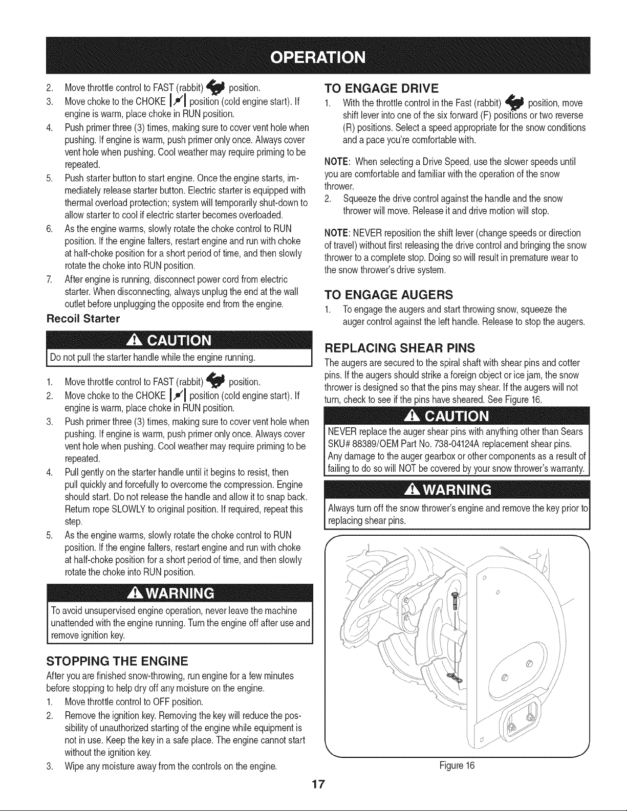
REPLACING SHEAR PINS
The augersare securedto the spiralshaftwith shearpins andcotter
pins.If the augersshouldstrikea foreignobjectorice jam, the snow
throweris designedso that the pins mayshear.If theaugerswill not
turn,checkto see if the pins havesheared.See Figure16.
NEVERreplacethe augershearpinswith anythingotherthanSears
SKU#88389/0EMPart No.738-04124Areplacementshearpins.
Anydamageto the augergearboxor othercomponentsas a resultof
[fa ngto do so w NOTbe coveredby yoursnow throwers warranty.
Alwaysturnoff the snowthrower'sengineandremovethe keyprior to
replacingshearpins.
o
iJ
Figure16
17
MAINTENANCE SCHEDULE
Beforeperforminganytypeof maintenance/service,disengageall
controlsand stoptheengine.Waituntilallmovingpartshavecometo
acompletestop.Disconnectsparkplugwireandgrounditagainstthe
enginetopreventunintendedstarting.Alwayswearsafetyglassesduring
operationor whileperforminganyadjustmentsor repairs.
Followthe maintenanceschedulegivenbelow.Thischart describes
serviceguidelinesonly. Usethe ServiceLogcolumnto keeptrackof
completedmaintenancetasks.To locate the nearest Sears Service
Centeror to scheduleservice,simplycontactSears at
1-800-4-MY-HOME®.
EachUseandevery5
hours
1st5 hours
Annuallyor 25hours
Annuallyor 50hours
Annuallyor 100hours
BeforeStorage
1. Engineoil level
2. Looseor missinghardware
3. Unit and engine.
1. Engineoil
1. Sparkplug
2. Controllinkagesand pivots
3. Wheels
4. Gearshaft andAugershaft
5. 4-WayChuteControlTM
1. Engineoil
1. Sparkplug
1. Fuelsystem
1. Check
2. Tightenor replace
3. Clean
1. Change
1. Check
2. Lubewithlightoil
3. Lubewithmultipurposeautogrease
4. Lubewithlightoil
5. Checkfor cableslackness
1. Change
1. Change
1. Runengineuntilit stopsfrom lack
of fuel
ENGINE MAINTENANCE
Beforelubricating,repairing,or inspecting,disengageall controls
Iandstop engine.Waituntilall movingpartshavecometo a complete
_stop.
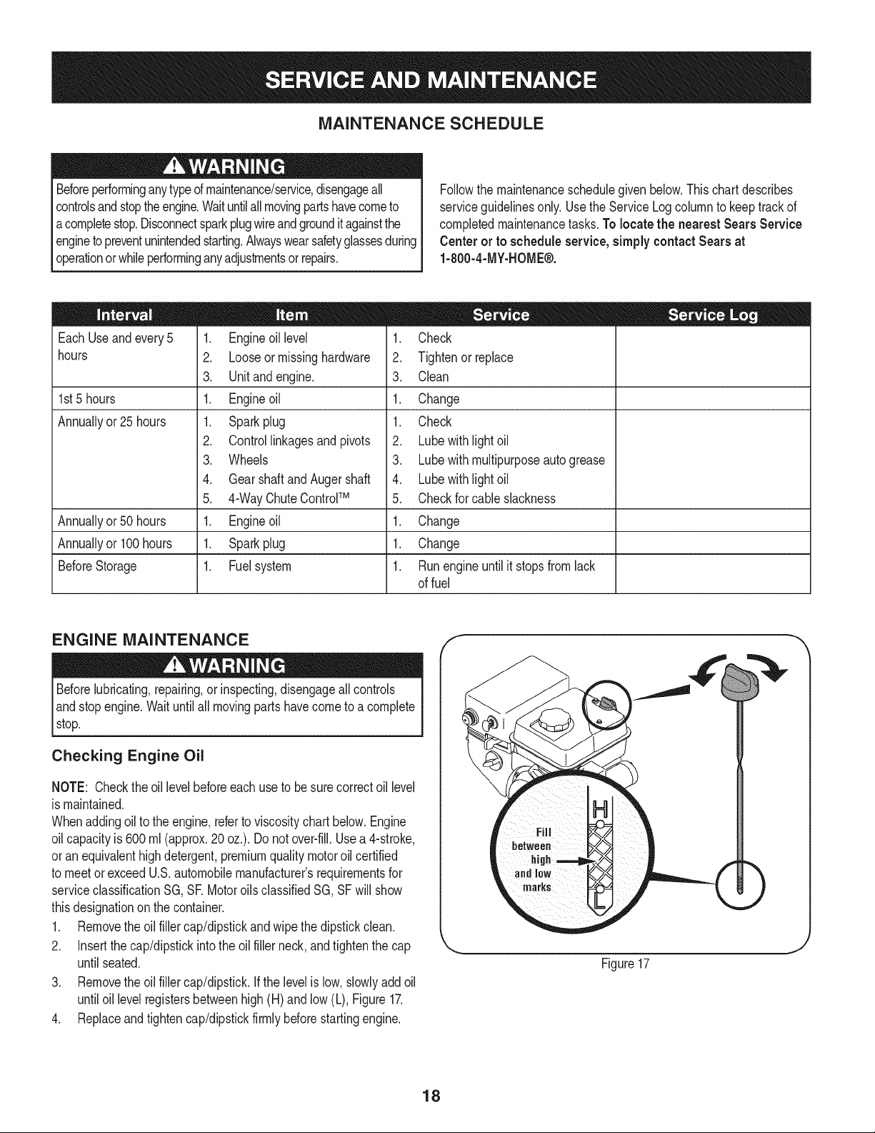
Checking Engine Oil
NOTE: Checktheoil levelbeforeeachuseto besurecorrectoil level
is maintained.
Whenaddingoilto the engine,referto viscositychart below.Engine
oilcapacityis 600 ml (approx.20 oz.). Donot over-fill.Usea 4-stroke,
oran equivalenthighdetergent,premiumquality motoroil certified
to meet or exceedU.S.automobilemanufacturer'srequirementsfor
serviceclassificationSG, SR MotoroilsclassifiedSG, SFwill show
thisdesignationon the container.
1. Removethe oil fillercap/dipstickandwipethe dipstickclean.
2. Insertthe cap/dipstickintothe oil filler neck,andtightenthe cap
until seated.
3. Removethe oil fillercap/dipstick.Ifthe levelis low, slowlyaddoil
untiloil levelregistersbetweenhigh(H) and low(L), Figure17.
4. Replaceand tighten cap/dipstickfirmlybeforestartingengine.
f
Figure17
18
Changing Engine Oil
NOTE:Changethe engineoilafter the first 5 hoursof operationand
oncea seasonorevery50hoursthereafter.
1. Drainfuelfromtankby runningengineuntilthe fuel tank is empty.
Besurefuel fill cap is secure.
2. Placesuitableoil collectioncontainerunderoil drainplug.
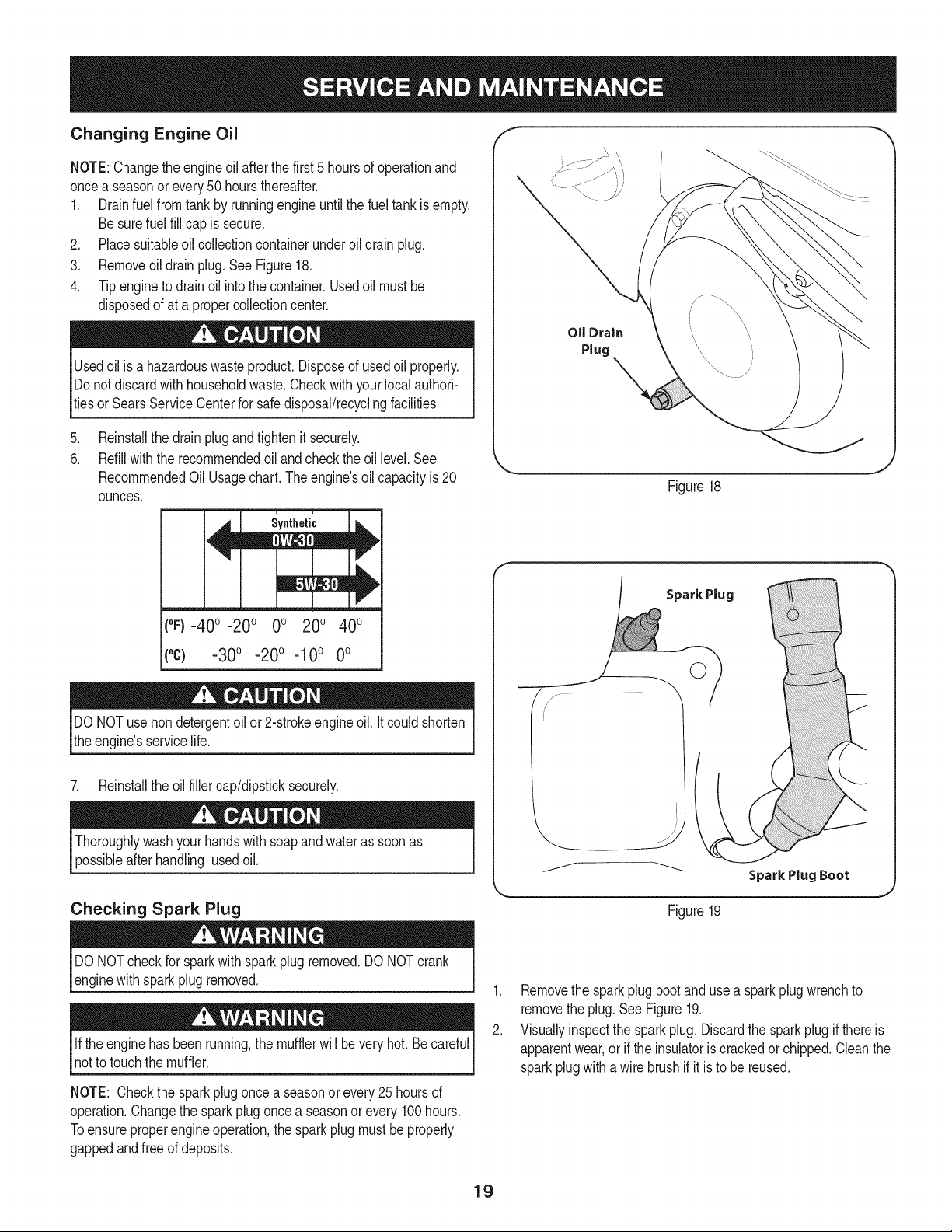
3. Removeoildrain plug.See Figure18.
4. Tip engineto drainoil intothe container.Usedoil mustbe
disposedof at a propercollectioncenter.
Usedoil is a hazardouswasteproduct.Disposeof usedoil properly.
Donotdiscardwith householdwaste.Checkwithyourlocalauthori-
tiesor SearsServiceCenterfor safedisposal/recyclingfacilities.
.
6.
Reinstallthe drainplugand tightenit securely.
Refillwiththe recommendedoil andcheckthe oil level.See
RecommendedOil Usagechart.Theengine'soil capacityis 20
ounces.
u i
Synthetic
(0F)-40o-20 o 0o 200 400
("c) -30° -20 ° -10° 0°
DONOTuse non detergentoil or 2-strokeengineoil. It couldshorten
the engine'sservicelife.
7. Reinstallthe oil fillercap/dipsticksecurely.
Thoroughlywashyour handswithsoapand water as soonas
possibleafterhandling usedoil.
Checking Spark Plug
Oil Drain
Plug
_=, ,J
Figure18
Spark Plug
©
Figure19
J
DO NOTcheckfor sparkwithspark plug removed.DO NOTcrank
enginewithsparkplug removed.
Ifthe enginehasbeenrunning,the mufflerwill be very hot.Be careful
notto touch the muffler.
NOTE: Checkthe sparkplug oncea seasonorevery 25 hoursof
operation.Changethe sparkplugoncea seasonor every100hours.
Toensureproperengineoperation,the sparkplugmustbe properly
gappedandfreeof deposits.
1. Removethe sparkplug bootand usea sparkplugwrenchto
removethe plug.See Figure19.
2. Visuallyinspectthe sparkplug. Discardthe sparkplugif thereis
apparentwear,or if the insulatoris crackedor chipped.Cleanthe
sparkplugwith a wire brushif it is to be reused.
19
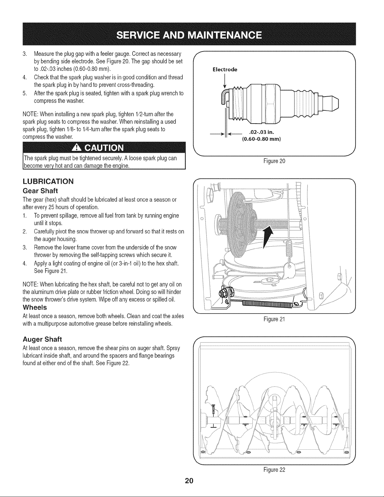
3. Measurethe pluggap with a feelergauge.Correctas necessary
by bendingsideelectrode.SeeFigure20. Thegap shouldbe set
to .02-.03inches (0.60-0.80ram).
4. Checkthat thesparkplugwasheris in good conditionandthread
the sparkplug in by handto preventcross-threading.
5. Afterthe sparkplug is seated,tightenwitha sparkplugwrenchto
compressthe washer.
NOTE:Wheninstallinga newsparkplug,tighten1/2-turnafterthe
sparkplugseatsto compressthe washer.Whenreinstallinga used
sparkplug,tighten1/8-to 1/4-turnafterthe sparkplugseatsto
compressthe washer.
hot and can ine.
f
J
Figure20
LUBRICATION
Gear Shaft
Thegear(hex)shaft shouldbe lubricatedat least oncea seasonor
afterevery25 hoursof operation.
1. Topreventspillage,removeall fuel fromtank by runningengine
until it stops.
2. Carefullypivotthe snowthrowerup andforwardso that it restson
theaugerhousing.
3. Removethe lowerframecover fromthe undersideof the snow
throwerby removingthe self-tappingscrewswhich secureit.
4. Applya lightcoatingof engineoil (or3-in-1oil) to the hexshaft.
SeeFigure21.
NOTE:Whenlubricatingthe hexshaft,be carefulnotto get any oil on
thealuminumdriveplateor rubberfrictionwheel.Doingsowill hinder
the snowthrower'sdrive system.Wipeoff anyexcessor spilledoil.
Wheels
At least oncea season,removebothwheels.Cleanandcoat theaxles
witha multipurposeautomotivegreasebeforereinstallingwheels.
Figure21
Auger Shaft
At least oncea season,removethe shearpinson augershaft.Spray
lubricantinsideshaft,andaroundthe spacersand flangebearings
foundat eitherend of the shaft.SeeFigure22.
f
\
2O
Figure22
J
SHAVE PLATE AND SKiD SHOES
Theshaveplateand skidshoesonthe bottomof the snowthrowerare
subjectto wear.They shouldbecheckedperiodicallyand replaced
whennecessary.
NOTE:Theskidshoes on this machinehavetwo wearedges.When
onesidewearsout, theycan be rotated1800to usethe otheredge.
Toremoveskidshoes:
1. Removethefour carriageboltsand hexflangenuts whichsecure
themtothe snowthrower.
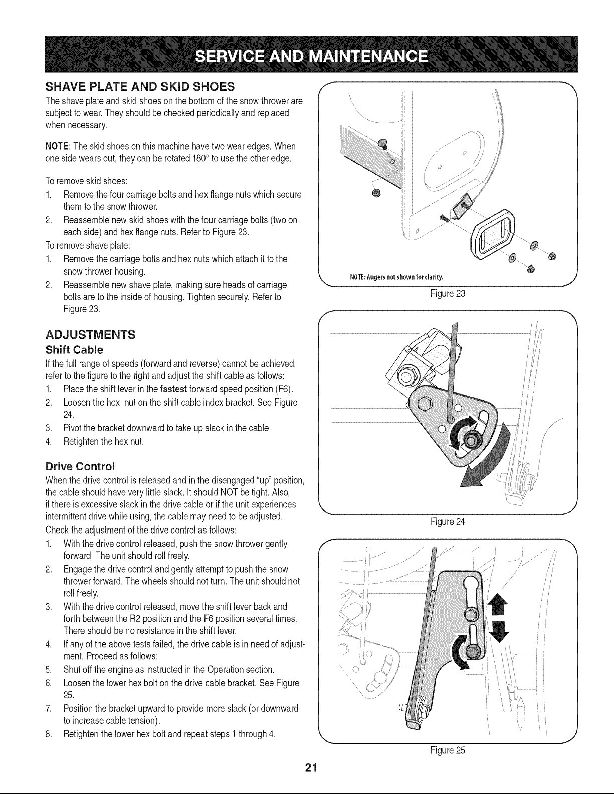
2. Reassemblenew skidshoeswith thefour carriagebolts (two on
eachside)and hexflangenuts.Referto Figure23.
Toremoveshaveplate:
1. Removethecarriageboltsand hexnutswhichattachit to the
snowthrowerhousing.
2. Reassemblenew shaveplate,makingsureheadsof carriage
boltsare to the insideof housing.Tightensecurely.Referto
Figure23.
NOTE:Augersnotshown for clarity.
Figure23
ADJUSTMENTS
Shift Cable
If thefull rangeof speeds(forwardandreverse)cannotbe achieved,
referto the figureto the rightandadjustthe shift cableas follows:
1. Placethe shiftleverin thefastest forwardspeedposition(F6).
2. Loosenthe hex nuton the shiftcable indexbracket.SeeFigure
24.
3. Pivotthe bracketdownwardto takeup slack inthe cable.
4. Retightenthehex nut.
Drive Control
Whenthedrivecontrolisreleasedandin thedisengaged"up"position,
the cableshouldhaveverylittle slack.It shouldNOTbetight. Also,
ifthereisexcessiveslackin thedrive cableor if the unitexperiences
intermittentdrivewhileusing,the cable mayneed to beadjusted.
Checktheadjustmentof the drivecontrolas follows:
1. Withthedrivecontrolreleased,pushthe snowthrowergently
forward.The unitshouldrollfreely.
2. Engagethe drivecontrolandgently attemptto pushthe snow
throwerforward.Thewheelsshouldnotturn.The unitshouldnot
rollfreely.
3. With thedrivecontrol released,movethe shift leverbackand
forthbetweenthe R2positionand the F6 positionseveraltimes.
Thereshouldbeno resistanceinthe shiftlever.
4. If anyof the abovetests failed,the drivecable isin needof adjust-
ment.Proceedas follows:
5. Shutoff theengineas instructedinthe Operationsection.
6. Loosenthe lowerhexbolt onthe drivecable bracket.See Figure
25.
7. Positionthe bracketupwardto providemoreslack(or downward
to increasecabletension).
8. Retightenthe lowerhex boltand repeatsteps1 through4.
f
Figure24
........
Figure25
/
21
Chute Control Rod
Toachievemorechute controlrodengagementinthe inputshaft under
the handlepanel,thechutecontrolrodwill haveto beadjusted.Refer
to Figure26.
Toadjustthis rod,proceedas follows:
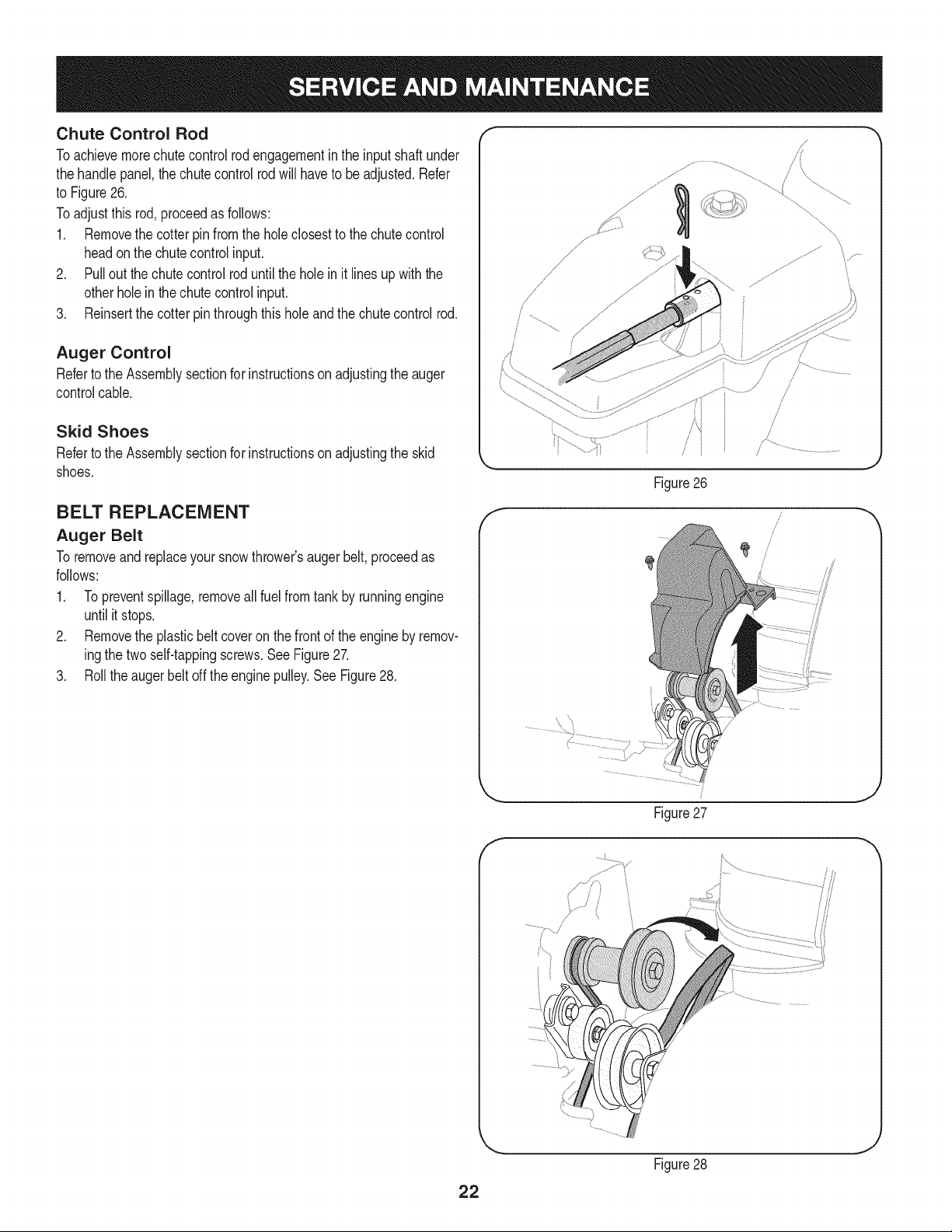
1. Removethe cotter pinfromthe holeclosestto the chutecontrol
headon the chutecontrolinput.
2. Pull out thechutecontrolrod until theholein it linesupwith the
otherholein thechutecontrolinput.
3. Reinsertthe cotterpin throughthisholeandthe chute control rod.
Auger Control
Referto the Assemblysectionfor instructionsonadjustingtheauger
controlcable.
Skid Shoes
Referto the Assemblysectionfor instructionsonadjustingthe skid
shoes.
BELT REPLACEMENT
Auger Belt
To removeand replaceyoursnowthrower'saugerbelt, proceedas
follows:
1. Topreventspillage,removeall fuel fromtank by runningengine
until it stops.
2. Removethe plasticbelt coveronthe frontof the engineby remov-
ingthe twoself-tappingscrews.See Figure27.
3. Rollthe augerbeltoff theenginepulley.See Figure28.
f
/
/
/
/
/
/
Figure26
f
Figure27
J
/
22
Figure28
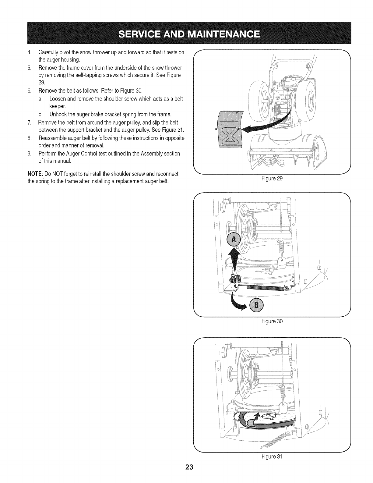
4. Carefullypivotthesnowthrowerupandforwardsothatitrestson
theaugerhousing.
5. Removetheframecoverfromtheundersideofthesnowthrower
byremovingtheself-tappingscrewswhichsecureit.SeeFigure
29.
6. Removethebeltasfollows.RefertoFigure30.
a. Loosenandremovetheshoulderscrewwhichactsasabelt
keeper.
b. Unhooktheaugerbrakebracketspringfromtheframe.
7. Removethebeltfromaroundtheaugerpulley,andslipthebelt
betweenthesupportbracketandtheaugerpulley.SeeFigure31.
8. Reassembleaugerbeltbyfollowingtheseinstructionsinopposite
orderandmannerofremoval.
9. PerformtheAugerControltestoutlinedintheAssemblysection
ofthismanual.
/
NOTE:Do NOTforgetto reinstallthe shoulderscrewand reconnect
the springto the frameafter installinga replacementaugerbelt.
Figure29
f
Figure30
f
23
Figure31
Drive Belt
To removeand replaceyoursnowthrower'sdrivebelt,proceedas
follows:
1. Topreventspillage,removeall fuel fromtank by runningengine
until it stops.
2. Removethe plasticbelt coveronthe frontof the engineby remov-
ingthe twoself-tappingscrews.See Figure27on previouspage.
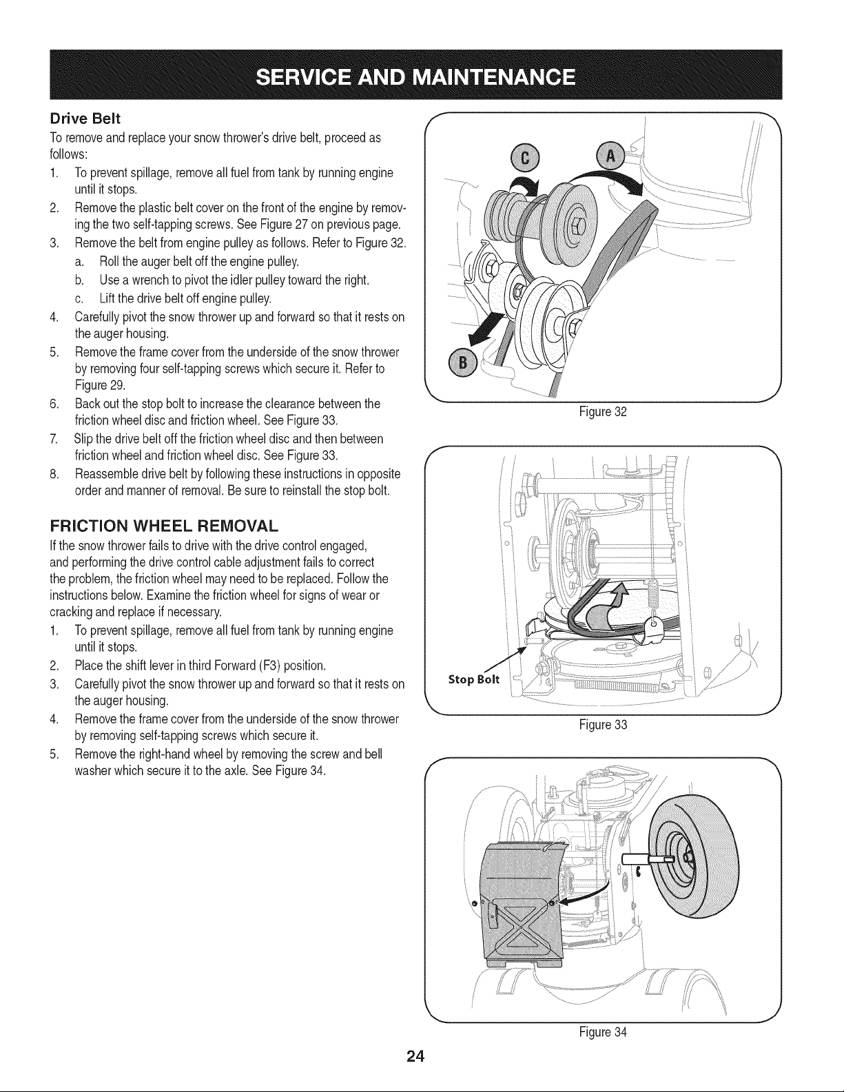
3. Removethe beltfromenginepulleyas follows.Referto Figure32.
a. Rollthe augerbeltoff theenginepulley.
b. Use a wrenchto pivotthe idler pulleytowardthe right.
c. Liftthe drivebelt offengine pulley.
4. Carefullypivotthe snow throwerup andforwardsothat it restson
the augerhousing.
5. Removethe framecoverfrom the undersideof thesnowthrower
by removingfour self-tappingscrewswhich secureit. Referto
Figure29.
6. Back outthe stopbolt to increasethe clearancebetweenthe
frictionwheeldiscand frictionwheel.See Figure33.
7. Slipthe drivebelt offthe frictionwheeldisc and thenbetween
frictionwheelandfrictionwheeldisc.See Figure33.
8. Reassembledrive beltby followingthese instructionsin opposite
orderand mannerof removal.Be sureto reinstallthe stopbolt.
FRICTION WHEEL REMOVAL
Ifthe snowthrowerfailsto drive with thedrivecontrol engaged,
andperformingthe drivecontrolcableadjustmentfailsto correct
the problem,the frictionwheelmayneedto be replaced.Followthe
instructionsbelow.Examinethe frictionwheelfor signsof wearor
crackingand replaceif necessary.
1. Topreventspillage,removeall fuel fromtank by runningengine
until it stops.
2. Placethe shiftleverin third Forward(F3) position.
3. Carefullypivotthe snowthrowerup andforwardso that it restson
theaugerhousing.
4. Removethe frame coverfrom the undersideof the snow thrower
by removingself-tappingscrewswhichsecureit.
5. Removethe right-handwheelby removingthe screwandbell
washerwhichsecureit to theaxle. See Figure34.
Figure32
J
f
Stop Bolt
Figure33
f
Figure34
J
24
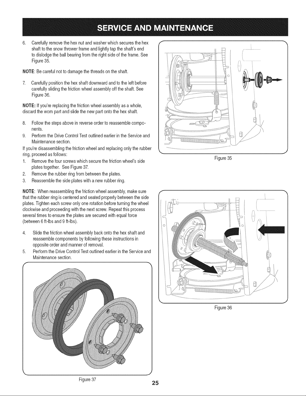
.
Carefullyremovethe hexnut and washerwhichsecuresthehex
shaftto the snowthrowerframeand lightlytap the shaft'send
to dislodgethe ball bearingfrom the rightsideof the frame.See
Figure35.
NOTE:Becarefulnot to damagethe threadson the shaft.
7. Carefullypositionthe hexshaftdownwardandto the left before
carefullyslidingthe frictionwheelassemblyoff the shaft. See
Figure36.
NOTE: If you'rereplacingthe frictionwheelassemblyas a whole,
discardthe wornpartand slidethe newpart ontothe hexshaft.
8. Followthe stepsabovein reverseorderto reassemblecompo-
nents.
9. Performthe DriveControlTestoutlinedearlierin the Serviceand
Maintenancesection.
If you'redisassemblingthefrictionwheeland replacingonly the rubber
ring,proceedas follows:
1. Removethefour screwswhich securethe frictionwheel'sside
platestogether. See Figure37.
2. Removethe rubberring from betweenthe plates.
3. Reassemblethe side plateswith a newrubberring.
Figure35
NOTE: Whenreassemblingthe frictionwheelassembly,makesure
thatthe rubberringis centeredand seatedproperlybetweenthe side
plates.Tighteneachscrewonlyone rotationbeforeturningthe wheel
clockwiseand proceedingwiththe nextscrew.Repeatthis process
severaltimes toensurethe platesaresecuredwith equalforce
(between6 ft-lbsand 9 ft-lbs).
4. Slide the frictionwheelassemblybackonto the hexshaftand
reassemblecomponentsby followingtheseinstructionsin
oppositeorderand mannerof removal.
5. Performthe DriveControlTestoutlinedearlierin the Serviceand
Maintenancesection.
f -,
\
Figure36
Figure37
25
Ifthe snowthrowerwillnot be usedfor30 daysor longer,or if it is the end of the snowseasonwhenthe lastpossibilityof snowis gone,the
equipmentneedsto be storedproperly.Followstorageinstructionsbelowto ensuretop performancefrom the snowthrowerfor manymoreyears.
PREPARING ENGINE
Enginesstoredover30 daysneedto be drainedof fuel to prevent
deteriorationandgumfrom formingin fuel systemor onessential
carburetorparts.If thegasolineinyourenginedeterioratesduring
storage,youmay needto havethe carburetor,and otherfuel system
components,servicedor replaced.
1. Removeall fuel fromtank by runningengineuntil it stops.Donot
attemptto pourfuel fromthe engine.
2. Changethe engineoil.
3. Removesparkplugand pour approximately1 oz. (30 rnl)of clean
engineoil intothe cylinder.Pullthe recoilstarterseveraltimesto
distributetheoil, and reinstallthe sparkplug.
4. Cleandebrisfromaroundengine,and under,around,andbehind
muffler.Applya lightfilmof oilon anyareasthatare susceptible
to rust.
• Storeina clean,dry andwellventilatedarea awayfrom anyap-
pliancethat operateswithaflameor pilotlight,suchas a furnace,
waterheater,or clothesdryer.Avoidany areawith a spark
producingelectricmotor,or wherepowertoolsare operated.
Neverstoresnowthrowerwith fuel intank indoorsor inpoorlyventi-
latedareas,wherefuel fumesmayreachan openflame,sparkor pilol
lightas on a furnace,water heater,clothesdryer orgas appliance.
• If possible,avoidstorageareaswithhigh humidity.
• Keepthe enginelevelin storage.Tiltingcan causefuel oroil
leakage.
PREPARING SNOW THROWER
Whenstoringthe snowthrowerin anunventilatedormetalstor-
age shed,careshouldbetakento rustprooftheequipment.Using
a light oilor silicone,coattheequipment,especiallyanychains,
springs,bearingsand cables.
• Removealldirt fromexteriorof engineand equipment.
• Followlubricationrecommendations.
• Storeequipmentin a clean,dry area.
26
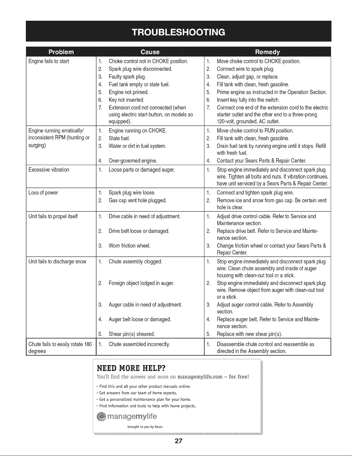
Enginefailsto start
Enginerunningerratically/
inconsistentRPM(huntingor
surging)
Excessivevibration
Lossof power
Unitfailsto propelitself
Unitfailsto dischargesnow
1. Chokecontrolnot inCHOKEposition.
2. Sparkplugwire disconnected.
3. Faultysparkplug.
4. Fueltank emptyor stalefuel.
5. Enginenot primed.
6. Keynot inserted.
7. Extensioncordnot connected(when
usingelectricstartbutton,on modelsso
equipped).
1. Enginerunningon CHOKE.
2. Stalefuel.
3. Wateror dirt in fuel system.
4. Over-governedengine.
1. Loosepartsor damagedauger.
1. Sparkplugwire loose.
2. Gascap venthole plugged.
1. Drivecable inneed of adjustment.
2. Drivebelt looseor damaged.
3. Wornfrictionwheel.
1. Chuteassemblyclogged.
2. Foreignobjectlodgedin auger.
3. Augercablein needof adjustment.
4. Augerbelt looseordamaged.
5. Shearpin(s) sheared.
1. Chuteassembledincorrectly.
1. Movechokecontrolto CHOKEposition.
2. Connectwireto sparkplug.
3. Clean,adjustgap,or replace.
4. Filltank with clean,freshgasoline.
5. Primeengineas instructedinthe OperationSection.
6. Insertkeyfully intothe switch.
7. Connectoneend of the extensioncordto the electric
starteroutletandthe otherendto a three-prong
120-volt,grounded,ACoutlet.
1. Movechokecontrolto RUNposition.
2. Filltank with clean,freshgasoline.
3. Drainfueltank by runningengineuntil it stops.Refill
withfreshfuel.
4. ContactyourSearsParts & RepairCenter.
1. Stopengineimmediatelyand disconnectsparkplug
wire.Tightenall boltsand nuts.If vibrationcontinues,
haveunit servicedbya SearsParts& RepairCenter.
1. Connectandtightenspark plugwire.
2. Removeiceand snowfromgascap. Becertainvent
holeis clear.
1. Adjustdrivecontrolcable. Referto Serviceand
Maintenancesection.
2. Replacedrive belt.Referto Serviceand Mainte-
nancesection.
3. Changefrictionwheelorcontactyour SearsParts&
RepairCenter.
1. Stopengineimmediatelyand disconnectsparkplug
wire.Cleanchuteassemblyand insideof auger
housingwith clean-outtoolor a stick.
2. Stopengineimmediatelyand disconnectsparkplug
wire.Removeobjectfromaugerwith clean-outtool
ora stick.
3. Adjustaugercontrolcable. Referto Assembly
section.
4. Replaceauger belt. Referto Serviceand Mainte-
nancesection.
5. Replacewith newshearpin(s).
Chutefailsto easilyrotate180 1. Disassemblechutecontroland reassembleas
degrees directedinthe Assemblysection.
NEED HORE HELP?
Yot,Fttfind. th_ answer a!ld mo_e on ma_age_y_ifeocom _ for free]
Find this and att your other product manua[s ontine.
Get answers from our team of home experts.
Get a personalized maintenance p[an for your home.
Find information and tools to he[p with home projects.
managemylife
b_e'_g_t_/_eyeu by Sea_s
27
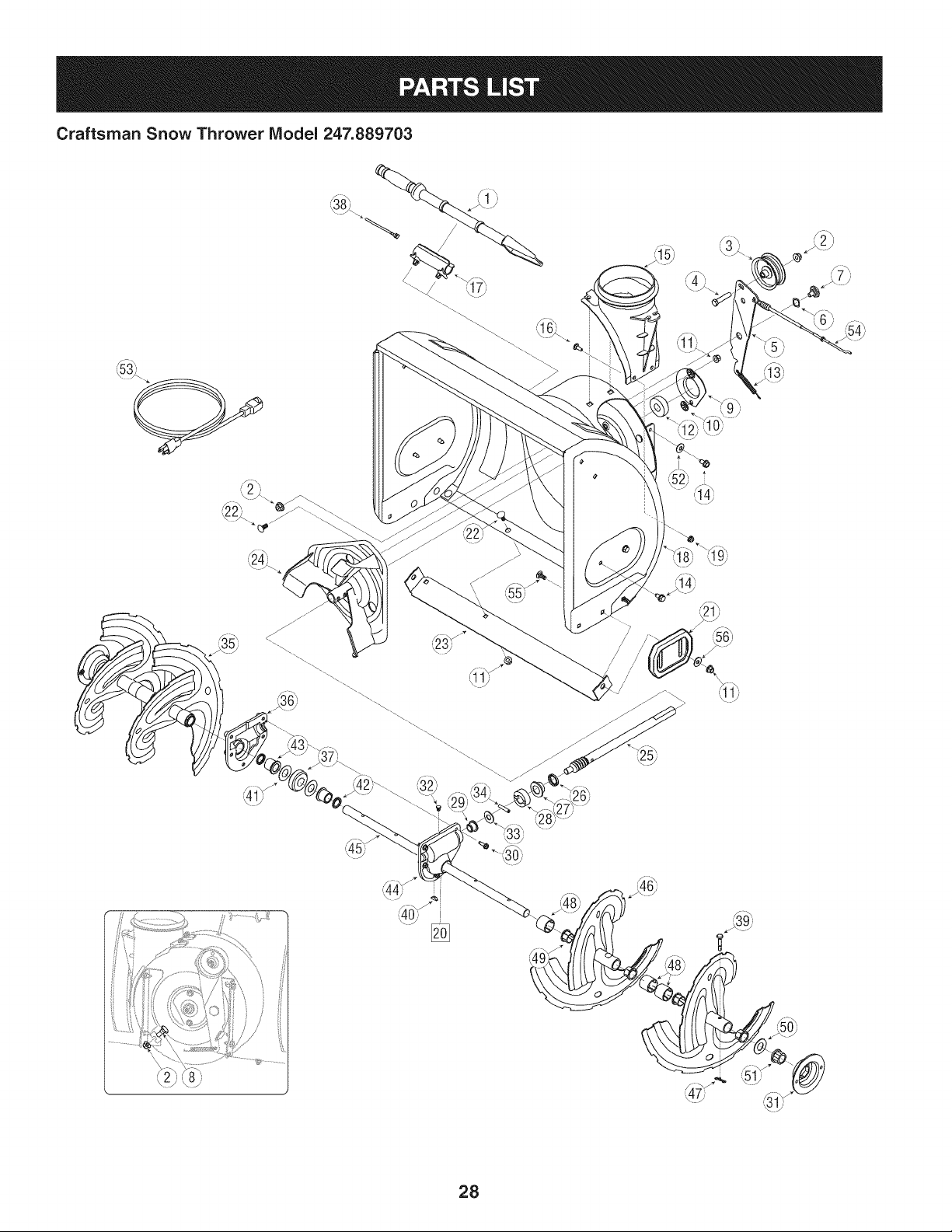
Craftsman Snow Thrower Model 247.889703
t
i )
_39_
- _' ',_1;f
28
Craftsman Snow Thrower IViodel 247.889703
D = 0
931-2643 Clean-OutTool
2. 712-04065 FlangeLockNut
3. 756-04224 Fiatidler Pulley
4. 710-0347 HexBolt,3/8-16x 1.75
5. 790-00080A-0637 AugerldlerBracket
6. 736-0174 WaveWasher
7. 938-0281 ShoulderScrew
8. 738-0143 ShoulderScrew
9. 790-00075 BearingHousing
10. 926-04012 PushNut
11. 712-04063 FlangeLockNut,5/16-18
12. 941-0309 Ball Bearing
13. 732-04460 ExtensionSpring
14. 710-04484 Screw,5/16-18x 0.750
15. J731-07525 J ChuteAdapter
16. 710-0703 CarriageScrew,1/4-20x 0.75
17. 731-2635 Clean-outToolMtg.Bracket
18. 684-04264-4044 AugerHousingAssembly,26-inch
19. 712-04064 FlangeLockNut, 1/4-20
20. 918-04172B GearboxAssembly,26-inch
21. 731-06439 SlideShoe
22. 710-0451 CarriageBolt
23. 790-00121-0721 ShavePlate
24. 684-04057A-0637 ImpellerAssembly
25. 917-04126 WormShaft
26. 721-0327 OilSeal
27. 741-0662 FlangeBearing
28. 718-04071 ThrustCollar
D = B
741-0663 FlangeBearing
30. 710-0642 Screw,1/4-20x 0.75
31. 790-00087A-0637 BearingHousing
32. 721-0325 Plug
33. 736-3084 FiatWasher
34. 715-04021 DowelPin
35. 684-04108-0637 SpiralAssembly-RH
36. 918-0123A ReducerHsg.-RH
37. 717-04861 Worm Gear,20T
38. 725-0157 CableTie
39. 738-04124A ShearPin
40. 914-0161 Key
41. 936-0351 Fiat Washer
42. 921-0338 OilSeal
43. 741-0661A FlangeBearing
44. 918-0124A ReducerHsg.-LH
45. 711-04284 Axle,Auger,26"
46. 684-04107-0637 SpiralAssembly-LH
47. 714-04040 BowTie CotterPin
48. 731-04870 Spacer
49. 741-0493A FlangeBushing
50. 736-0188 FiatWasher
51. 941-0245 Hex FlangeBearing
52. 736-0242 BellWasher
53. 929-0071A ExtensionCord
54. 746-04230A AugerClutchCable
55. 710-0276 Screw,Carriage,5/16-18x 1.00
56. 936-0159 Washer,Fiat, .349x .879x .063
29
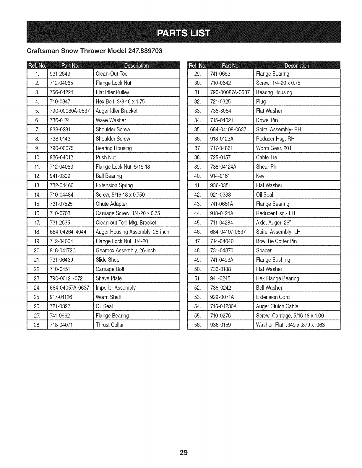
Craftsman Snow Thrower IViodel 247.889703
_'.'X
'J2_\
=
<
......................................................,_!:...........................¢o_......................
3O
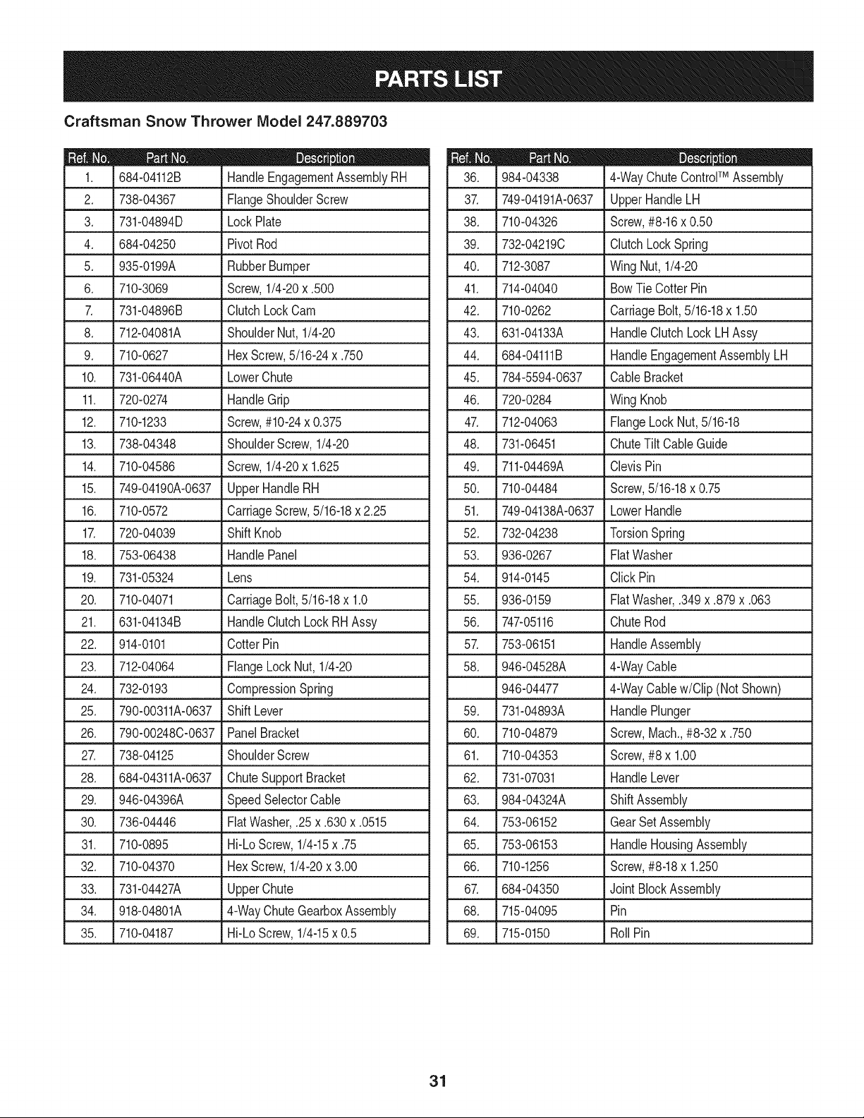
Craftsman Snow Thrower Model 247.889703
D = 0 0
684-04112B HandleEngagementAssemblyRH
2. _ 738-04367 _FlangeShoulderScrew
3. 731-04894D LockPlate
4. 684-04250 PivotRod
5. 935-0199A RubberBumper
6. 710-3069 Screw,1/4-20x .500
7. 731-04896B ClutchLockCam
8. 712-04081A ShoulderNut, 1/4-20
9. 710-0627 HexScrew,5/16-24x .750
10. 731-06440A LowerChute
11. 720-0274 HandleGrip
12. 710-1233 Screw,#10-24x 0.375
13. 738-04348 ShoulderScrew,1/4-20
14. 710-04586 Screw,1/4-20x 1.625
15. 749-04190A-0637 UpperHandleRH
16. 710-0572 CarriageScrew,5/16-18x 2.25
17. 720-04039 Shift Knob
18. 753-06438 HandlePanel
19. 731-05324 Lens
20. 710-04071 CarriageBolt,5/16-18x 1.0
21. 631-04134B HandleClutchLock RH Assy
22. 914-0101 CotterPin
23. 712-04064 FlangeLockNut, 1/4-20
24. 732-0193 CompressionSpring
25. 790-00311A-0637 ShiftLever
26. 790-00248C-0637 PanelBracket
27. 738-04125 ShoulderScrew
28. 684-04311A-0637 ChuteSupportBracket
29. 946-04396A SpeedSelectorCable
30. 736-04446 FiatWasher,.25 x .630x .0515
31. 710-0895 Hi-LoScrew,1/4-15x .75
32. 710-04370 HexScrew,1/4-20x 3.00
33. 731-04427A UpperChute
34. _ 918-04801A J 4-WayChuteGearboxAssembly
35. 710-04187 Hi-LoScrew,1/4-15x 0.5
m = O
984-04338 4-WayChuteControlTM Assembly
37. 749-04191A-0637 UpperHandleLH
38. 710-04326 Screw,#8-16x 0.50
39. 732-04219C ClutchLockSpring
40. 712-3087 WingNut, 1/4-20
41. 714-04040 BowTie CotterPin
42. 710-0262 CarriageBolt, 5/16-18x 1.50
43. 631-04133A HandleClutchLock LHAssy
44. 684-04111B HandleEngagementAssemblyLH
45. 784-5594-0637 CableBracket
46.
720-0284 WingKnob
47. 712-04063 FlangeLock Nut,5/16-18
48. 731-06451 ChuteTiltCableGuide
49. 711-04469A ClevisPin
50. 710-04484 Screw,5/16-18x 0.75
51. 749-04138A-0637 LowerHandle
52. 732-04238 TorsionSpring
53. 936-0267 FiatWasher
54. 914-0145 ClickPin
55. 936-0159 FiatWasher,.349x .879x .063
56. 747-05116 ChuteRod
57. 753-06151 HandleAssembly
58. 946-04528A 4-WayCable
946-04477 4-WayCablew/Clip (NotShown)
59. 731-04893A HandlePlunger
60. 710-04879 Screw,Mach.,#8-32 x .750
61. 710-04353 Screw,#8 x 1.00
62. 731-07031 HandleLever
63. 984-04324A ShiftAssembly
64. 753-06152 GearSet Assembly
65. 753-06153 HandleHousingAssembly
66. 710-1256 Screw,#8-18x 1.250
67. 684-04350 Joint BlockAssembly
68. 715-04095 Pin
69. 715-0150 Roll Pin
31
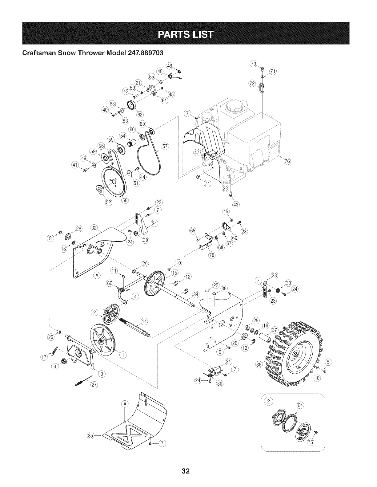
Craftsman Snow Thrower Model 247.889703
i,73/
<
32
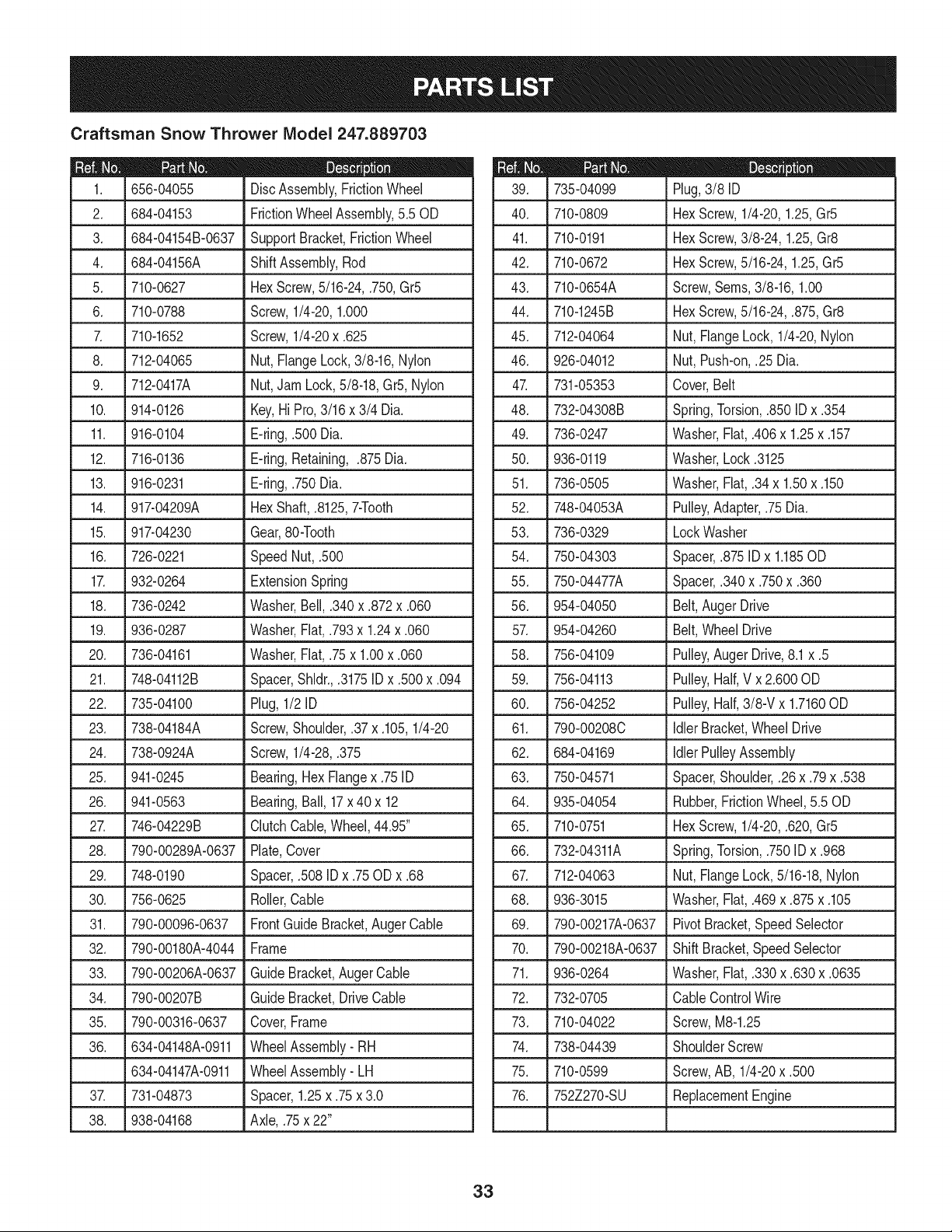
Craftsman Snow Thrower IViodel 247.889703
|= 0 =
656-04055 DiscAssembly,FrictionWheel
2. 684-04153 FrictionWheelAssembly,5.50D
3_ L684-04154B-0637_Supp°rt Bracket,Friction Wheel
4. 684-04156A ShiftAssembly,Rod
5. 710-0627 HexScrew,5/16-24,.750,Gr5
6. 710-0788 Screw,1/4-20,1.000
7. 710-1652 Screw,1/4-20x .625
8. 712-04065 Nut,FlangeLock,3/8-16,Nylon
9. 712-0417A Nut,JamLock,5/8-18,Gr5,Nylon
10. 914-0126 Key,Hi Pro,3/16x 3/4 Dia.
11. 916-0104 E-ring,.500 Dia.
12. 716-0136 E-ring,Retaining, .875Dia.
13. 916-0231 E-ring,.750Dia.
14. 917-04209A Hex Shaft,.8125,7-Tooth
15. 917-04230 Gear,80-Tooth
16. 726-0221 SpeedNut, .500
17. 932-0264 ExtensionSpring
18. 736-0242 Washer,Bell, .340x .872x .060
19. .936-0287 LWasher,Flat,.793x 1.24x .060
20. 736-04161 Washer,Flat,.75x 1.00x .060
21. 748-04112B Spacer,Shldr.,.3175ID x .500x .094
22. 735-04100 Plug,1/2 ID
23. 738-04184A Screw,Shoulder,.37 x .105,1/4-20
24. 738-0924A Screw,1/4-28,.375
25. 941-0245 Bearing,Hex Flangex .75ID
26. 941-0563 Bearing,Ball, 17x 40 x 12
27. ,746-04229B _ClutchCable,Wheel,44.95"
28. 790-00289A-0637 Plate,Cover
29. 748-0190 Spacer,.508 ID x .75ODx .68
30. 756-0625 Roller,Cable
31. 790-00096-0637 FrontGuide Bracket,AugerCable
32. 790-00180A-4044 Frame
33. 790-00206A-0637 GuideBracket,AugerCable
34. 790-00207B GuideBracket,DriveCable
35. 790-00316-0637 Cover,Frame
36. 634-04148A-0911 WheelAssembly- RH
634-04147A-0911 WheelAssembly- LH
37. 731-04873 Spacer,1.25x .75x 3.0
38. 938-04168 Axle,.75x 22"
D = O O
735-04099 Plug,3/8 ID
40. 710-0809 HexScrew,1/4-20,1.25,Gr5
41. 710-0191 HexScrew,3/8-24,1.25,Gr8
42. 710-0672 HexScrew,5/16-24,1.25,Gr5
43. 710-0654A Screw,Seres,3/8-16,1.00
44. 710-1245B HexScrew,5/16-24,.875,Gr8
45. 712-04064 Nut, FlangeLock, 1/4-20,Nylon
46. 926-04012 Nut, Push-on,.25 Dia.
47. 731-05353 Cover,Belt
48. 732-04308B Spring,Torsion,.850 ID x .354
49. 736-0247 Washer,Flat,.406x 1.25x .157
50. 936-0119 Washer,Lock .3125
51. 736-0505 Washer,Flat,.34x 1.50x .150
52. 748-04053A Pulley,Adapter,.75Dia.
53. 736-0329 LockWasher
54. 750-04303 Spacer,.875IDx 1.185OD
55. 750-04477A Spacer,.340x .750x .360
56. 954-04050 Belt,AugerDrive
57. 954-04260 Belt,WheelDrive
58. 756-04109
59. 756-04113
60. 756-04252
61. 790-00208C
62. 684-04169
63. 750-04571
64. 935-04054
65. 710-0751
Pulley,AugerDrive,8.1x .5
Pulley,Half,V x 2.600OD
Pulley,Half,3/8-V x 1.7160OD
Idler Bracket,WheelDrive
Idler PulleyAssembly
Spacer,Shoulder,.26x .79x .538
Rubber,FrictionWheel, 5.50D
HexScrew,1/4-20,.620, Gr5
66. 732-04311A
67. 712-04063
68. 936-3015
69. 790-00217A-0637
70. 790-00218A-0637
71. 936-0264
72. 732-0705
73. 710-04022
Spring,Torsion,.750ID x .968
Nut, FlangeLock,5/16-18,Nylon
Washer,Flat,.469x .875x .105
PivotBracket,SpeedSelector
ShiftBracket,SpeedSelector
Washer,Fiat,.330x .630x .0635
CableControlWire
Screw,M8-1.25
74. 738-04439 ShoulderScrew
75. 710-0599 Screw,AB, 1/4-20x .500
76. 752Z270-SU ReplacementEngine
33
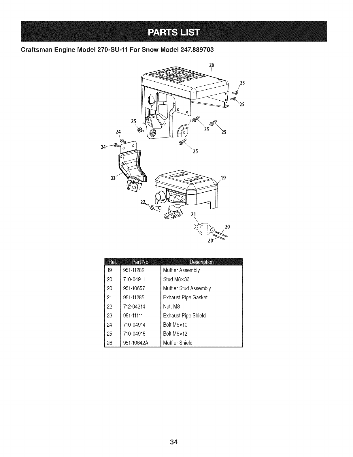
Craftsman Engine IViodel 270=SU=11 For Snow IViodel 247.889703
25
_2s
24
23- ,_
21
m
19
20
20
21
22
23
24
25
26
951-11282
710-04911
951-10657
951-11285
712-04214
951-11111
710-04914
710-04915
951-10642A
m = O O
MufflerAssembly
StudM8x36
MufflerStudAssembly
ExhaustPipe Gasket
Nut,M8
ExhaustPipe Shield
Bolt M6xl0
Bolt M6x12
MufflerShield
34
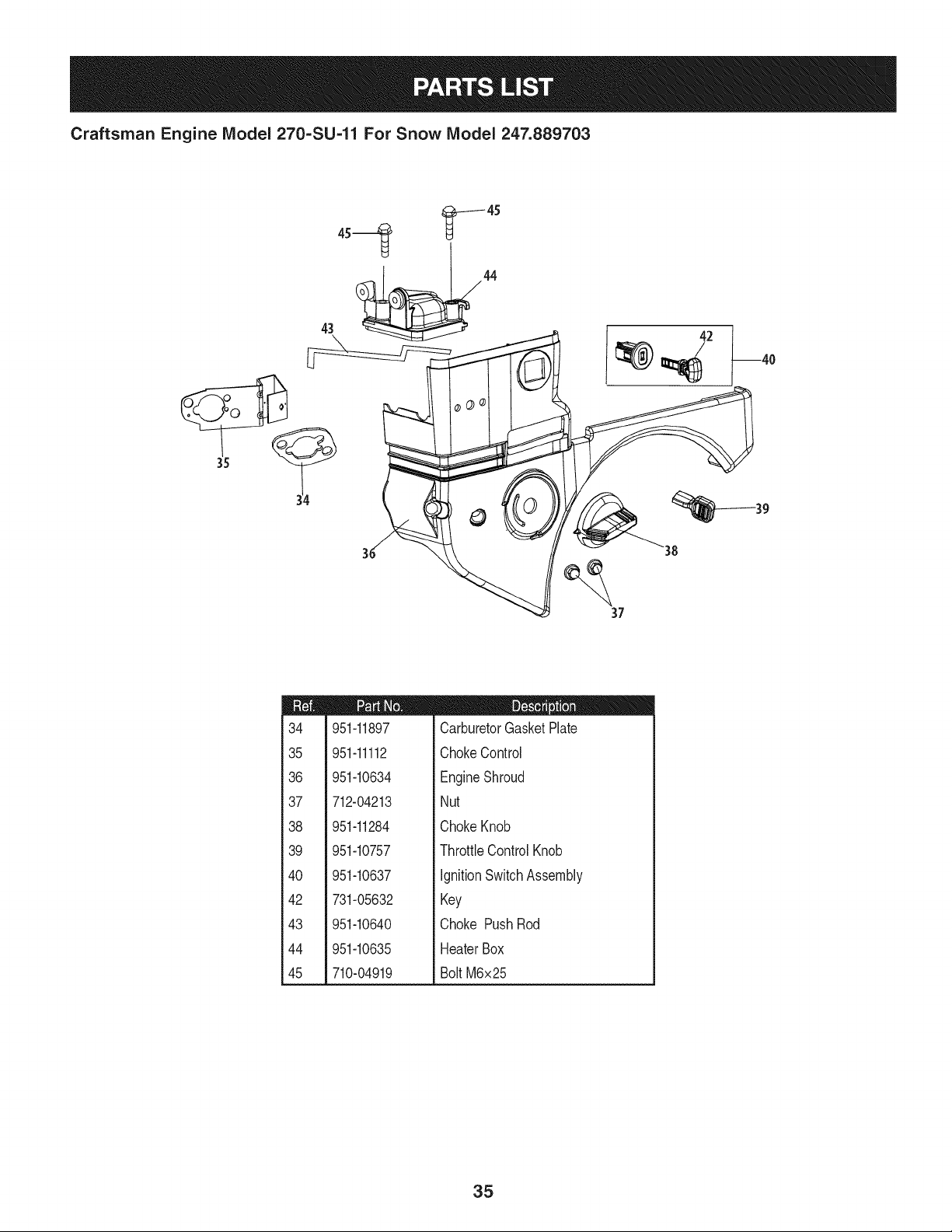
Craftsman Engine Model 270=SU=11 For Snow Model 247.889703
43 _44
J
38 39
37
m
34
35
36
37
38
39
4O
42
43
44
45
951-11897
951-11112
951-10634
712-04213
951-11284
951-10757
951-10637
731-05632
951-10640
951-10635
710-04919
D = O Q
CarburetorGasketPlate
ChokeControl
EngineShroud
Nut
ChokeKnob
ThrottleControlKnob
IgnitionSwitchAssembly
Key
Choke PushRod
HeaterBox
Bolt M6x25
35
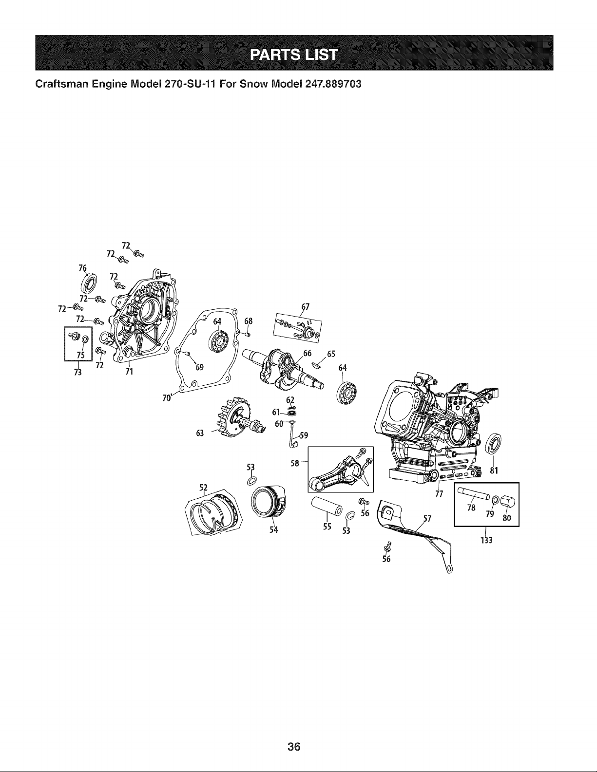
Craftsman Engine IViodel 270=SU=11 For Snow IViodel 247.889703
71
77
36
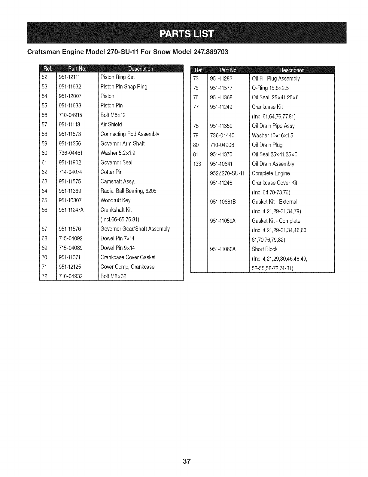
Craftsman Engine IViodel 270=SU=11 For Snow IViodel 247.889703
m
52
53
54
55
56
57
58
59
6O
61
62
63
64
65
66
67
68
69
7O
71
72
951-12111
951-11632
951-12007
951-11633
710-04915
951-11113
951-11573
951-11356
736-04461
951-11902
714-04074
951-11575
951-11369
951-10307
951-11247A
951-11576
715-04092
715-04089
951-11371
951-12125
710-04932
D = O O
PistonRingSet
PistonPinSnap Ring
Piston
PistonPin
Bolt M6x12
Air Shield
ConnectingRodAssembly
GovernorArm Shaft
Washer5.2xl.9
GovernorSeal
CotterPin
CamshaftAssy.
RadialBallBearing,6205
WoodruffKey
CrankshaftKit
(Incl.66-65,76,81)
GovernorGear/ShaftAssembly
DowelPin7x14
DowelPin9x14
CrankcaseCoverGasket
CoverComp,Crankcase
Bolt M8x32
m
73
75
76
77
78
79
8O
81
133
951-11283
951-11577
951-11368
951-11249
951-11350
736-04440
710-04906
951-11370
951-10641
Oil FillPlugAssembly
O-Ring15.8x2.5
OilSeal,25x41.25x6
CrankcaseKit
(Incl.61,64,76,77,81)
Oil DrainPipeAssy.
Washer10x16x1.5
Oil DrainPlug
OilSeal 25x41.25x6
Oil DrainAssembly
952Z270-SU-11
951-11246
951-10661B
951-11059A
951-11060A
CompleteEngine
CrankcaseCoverKit
(Incl.64,70-73,76)
GasketKit- External
(Incl.4,21,29-31,34,79)
GasketKit- Complete
(Inc1.4,21,29-31,34,46,60,
61,70,76,79,82)
ShortBlock
(Incl.4,21,29,30,46,48,49,
52-55,58-72,74-81)
37
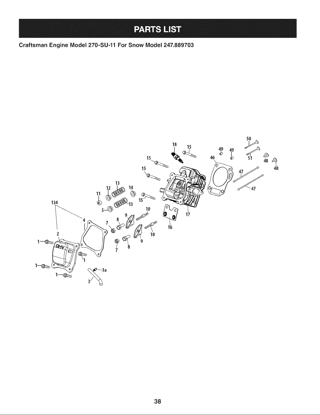
Craftsman Engine IViodel 270=SU-11 For Snow IViodel 247.889703
134
2
13
12 I_ 14
18
17
5O
46
38
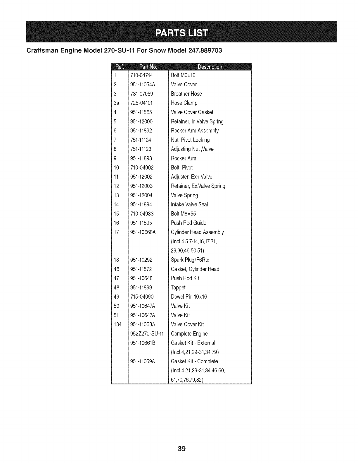
Craftsman Engine IViodel 270=SU=11 For Snow IViodel 247.889703
m
1
2
3
3a
4
5
6
7
8
9
10
11
12
13
14
15
16
17
18
46
47
48
49
5O
51
134
710-04744
951-11054A
731-07059
726-04101
951-11565
951-12000
951-11892
751-11124
751-11123
951-11893
710-04902
951-12002
951-12003
951-12004
951-11894
710-04933
951-11895
951-10668A
951-10292
951-11572
951-10648
951-11899
715-04090
951-10647A
951-10647A
951-11063A
952Z270-SU-11
951-10661B
951-11059A
D = W O
Bolt M6x16
ValveCover
BreatherHose
HoseClamp
ValveCoverGasket
Retainer,In.ValveSpring
RockerArmAssembly
Nut, PivotLocking
AdjustingNut,Valve
RockerArm
Bolt,Pivot
Adjuster,ExhValve
Retainer,Ex.ValveSpring
ValveSpring
IntakeValveSeal
Bolt M8x55
PushRodGuide
CylinderHeadAssembly
(Incl.4,5,7-14,16,17,21,
29,30,46,50,51)
SparkPlug/F6Rtc
Gasket,CylinderHead
PushRod Kit
Tappet
DowelPin 10x16
ValveKit
ValveKit
ValveCover Kit
CompleteEngine
GasketKit- External
(Incl.4,21,29-31,34,79)
GasketKit- Complete
(Incl.4,21,29-31,34,46,60,
61,70,76,79,82)
39
Craftsman Engine IViodel 270=SU=11 For Snow IViodel 247.889703
31
32
33_
4O
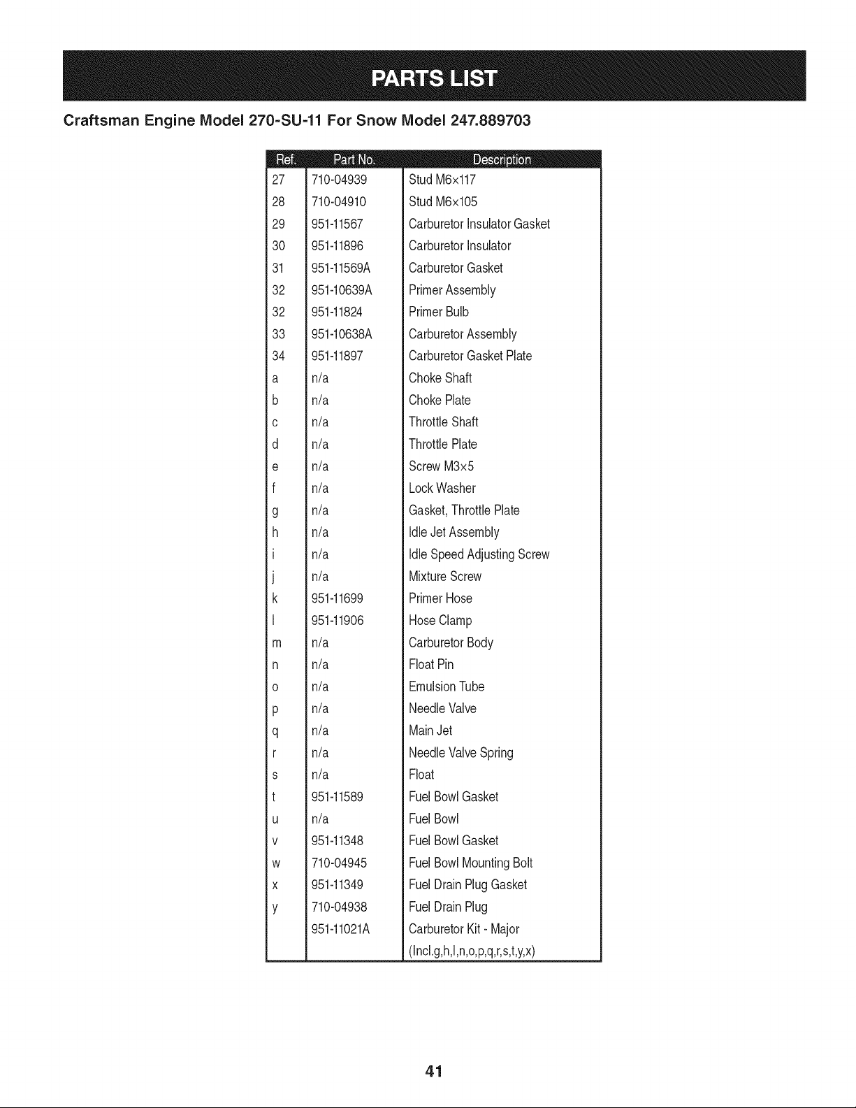
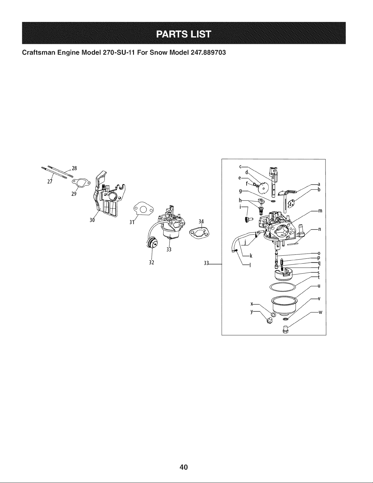
Craftsman Engine IViodel 270=SU=11 For Snow IViodel 247.889703
m
27
28
29
30
31
32
32
33
34
a
b
C
d
e
f
g
h
I
J
k
I
m
n
o
P
q
r
s
t
U
V
W
X
Y
710-04939
710-04910
951-11567
951-11896
951-11569A
951-10639A
951-11824
951-10638A
951-11897
n/a
n/a
n/a
n/a
n/a
n/a
n/a
n/a
n/a
n/a
951-11699
951-11906
n/a
n/a
n/a
n/a
n/a
n/a
n/a
951-11589
n/a
951-11348
710-04945
951-11349
710-04938
951-11021A
D = O O
Stud M6x117
Stud M6x105
CarburetorInsulatorGasket
CarburetorInsulator
CarburetorGasket
PrimerAssembly
PrimerBulb
CarburetorAssembly
CarburetorGasketPlate
ChokeShaft
ChokePlate
ThrottleShaft
ThrottlePlate
ScrewM3x5
LockWasher
Gasket,ThrottlePlate
IdleJet Assembly
Idle SpeedAdjustingScrew
MixtureScrew
PrimerHose
HoseClamp
CarburetorBody
FloatPin
EmulsionTube
NeedleValve
MainJet
NeedleValveSpring
Float
FuelBowlGasket
FuelBowl
FuelBowlGasket
FuelBowlMountingBolt
FuelDrainPlugGasket
FuelDrainPlug
CarburetorKit- Major
(Incl.g,h,l,n,o,p,q,r,s,t,y,x)
41
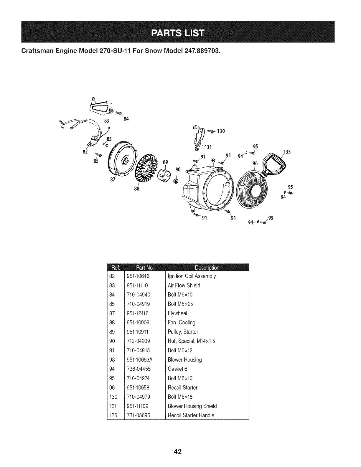
Craftsman Engine IViodel 270-SU-11 For Snow IViodel 247.889703.
84
82
87
88
89
_1 _130
31
#
94_ 135
96
;o
95
_'91 91 94.4 _95
m
82
83
84
85
87
88
89
90
91
93
94
95
96
130
131
135
951-10646
951-11110
710-04940
710-04919
951-12416
951-10909
951-10911
712-04209
710-04915
951-10663A
736-04455
710-04974
951-10658
710-04979
951-11109
731-05696
D = O O
IgnitionCoil Assembly
Air FlowShield
BoltM6xlO
BoltM6x25
Flywheel
Fan,Cooling
Pulley,Starter
Nut,Special,M14x1.5
BoltM6x12
BlowerHousing
Gasket6
BoltM6xlO
RecoilStarter
BoltM6x18
BlowerHousingShield
RecoilStarterHandle
42
Craftsman Engine IViodel 270=SU=11 For Snow IViodel 247.889703.
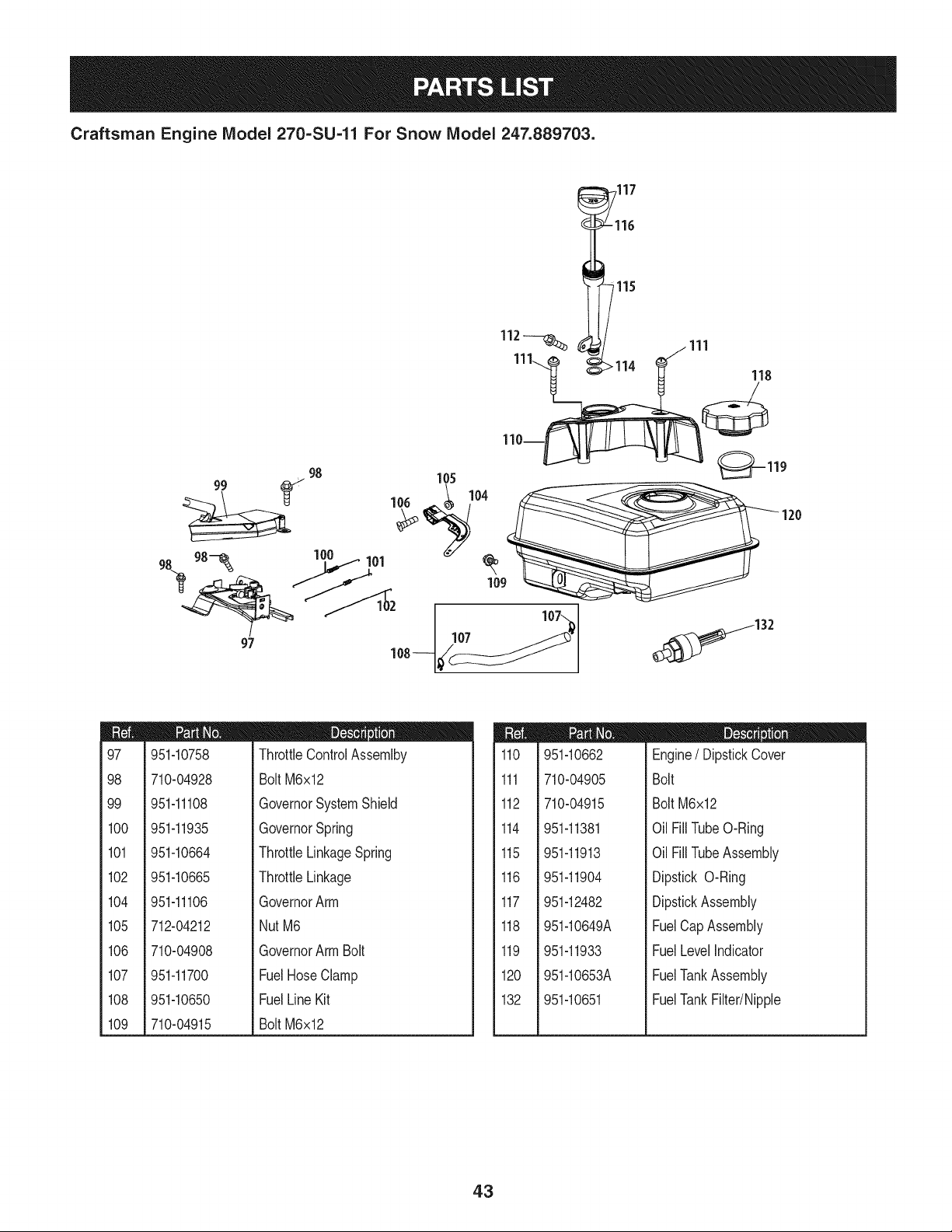
97
m
97
98
99
100
101
102
104
105
106
107
108
109
951-10758
710-04928
951-11108
951-11935
951-10664
951-10665
951-11106
712-04212
710-04908
951-11700
951-10650
710-04915
D = O 0
ThrottleControlAssemlby
BoltM6x12
GovernorSystemShield
GovernorSpring
ThrottleLinkageSpring
ThrottleLinkage
GovernorArm
NutM6
GovernorArmBolt
FuelHoseClamp
FuelLineKit
BoltM6x12
m
110
111
112
114
115
116
117
118
119
120
132
951-10662
710-04905
710-04915
951-11381
951-11913
951-11904
951-12482
951-10649A
951-11933
951-10653A
951-10651
D = O @
Engine/ DipstickCover
Bolt
Bolt M6x12
Oil FillTubeO-Ring
Oil FillTubeAssembly
Dipstick O-Ring
DipstickAssembly
FuelCapAssembly
FuelLevelIndicator
FuelTankAssembly
FuelTankFilter/Nipple
43
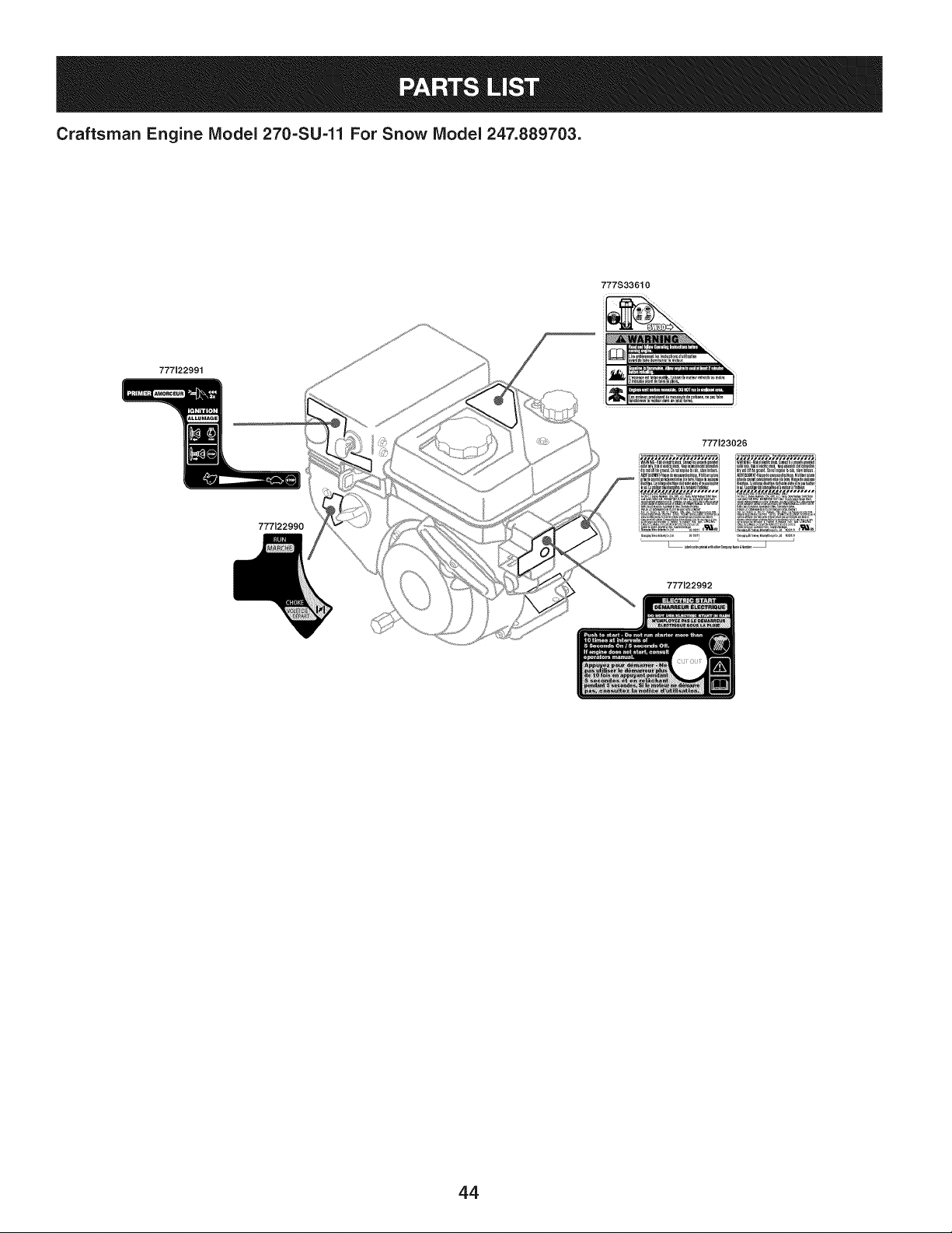
Craftsman Engine Model 270=SU=11 For Snow Model 247.889703.
777122991
777S33610
i ,
777123026
777122990
777122992
44
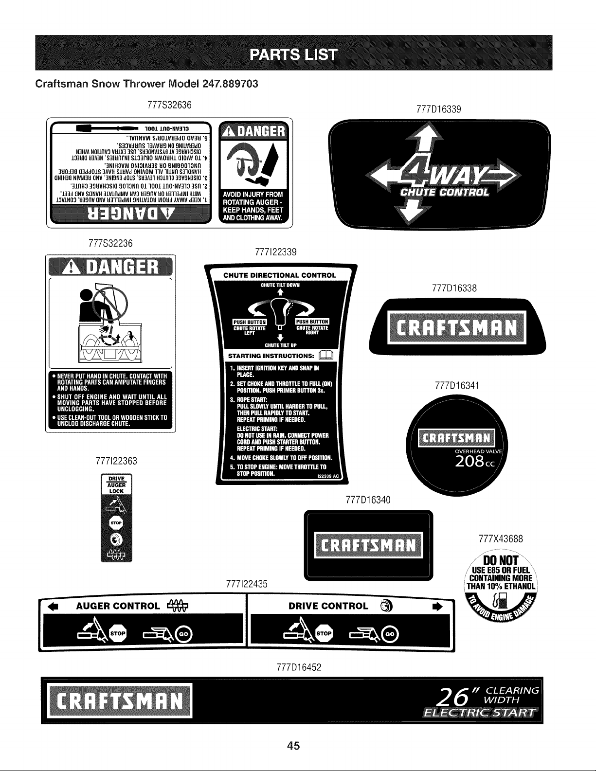
Craftsman Snow Thrower Model 247.889703
777S32636
777D16339
• -- " _ 3001 lnO-NV]lO •
7VflNVW S,UOIVU3dO QV]U "_
"S]3VdUflS ]]AVU9 NO9NIIVH]dO
N]HM NOllflVO VU.LX] 389 "88]GNVlS18 iV 399VH3810
IO]UIO 93A]N 'S]IUnFNI S13]rSO NMOUH10IOAV 01 "_
']NIHOVW 9NIOIA838 UO 9NI99013Nn
3UOJ]8 g]aa01S ]AVH SlUVa 9NIAO_ 33V lllNfl S]3QNVH
ONIH]8 HIYFJ3U6NV '3NIgN] d01S 'SH3A31 HO/fl]O ]gVgN]SIO "8
"]lflHO 39UVHOSIO 90]ONfl 011001 lflO-NV]13 ]Sfl '_
"1334QNV SQNVH31Vlfld_JV NV3 _39flV 80 U]]13d_l HIlM
IOVINO3 "U39flV ONVU3113d_l 9NIIVIOU _JOU4AVMV d33H ' L
777S32236
777122339
777122363
STARTING INSTRUCTIONS:
777D16338
777D16341
777D16340
777X43688
AUGER CONTROL
777122435
DRIVE CONTROL (_
i/'USE_S_'I_UEL
, CONTAININGMORE
THAN10% ETHANOL
W
777D16452
45
MTD CONSUMER GROUP INC (MTD), the California Air Resources Board (CARB)
and the United States Environment Protection Agency (U. S. EPA)
Emission Control System Warranty Statement
(Owner's Defect Warranty Rights and Obligations)
EMISSIONCONTROLSYSTEMCOVERAGEIS APPLICABLETOCERTIFIEDENGINESPURCHASEDINCALIFORNIAIN2005ANDTHERE-
AFTER,WHICHARE USEDINCALIFORNIA,ANDTO CERTIFIEDMODELYEAR2005AND LATERENGINESWHICHARE PURCHASEDAND
USEDELSEWHEREIN THE UNITEDSTATES.
Californiaandelsewherein the UnitedStatesEmissionControlDefectsWarrantyCoverage
The CaliforniaAir ResourcesBoard(CARB),U.S. EPAand MTDare pleasedto explaintheemissionscontrolsystemwarrantyonyour modelyear
2006and latersmalloff-roadengine.In California,new smalloff-roadenginesmustbe designed,builtand equippedto meettheStatesanti-smog
standards.Elsewhereinthe UnitedStates,newnon-road,spark-ignitionenginescertifiedfor model2005and later,mustmeetsimilarstandardsset
forthby the U. S. EPA.MTDmustwarrantythe emissioncontrolsystemonyourenginefor the periodof timelisted below,providedtherehasbeen
noabuse,neglector impropermaintenanceof your smalloff-roadengine.
Youremissioncontrolsystemmayincludepartssuch as the carburetor,fuel-injectionsystem,the ignitionsystem,andcatalyticconverter,fueltanks,
fuel lines,fuel caps,valves,canisters,filters,vaporhoses,clamps,connectors,andotherassociatedemission-relatedcomponents.
Wherea warrantableconditionexists,MTDwill repairyoursmall off-roadengineat nocost to yourincludingdiagnosis,partsand labor.
MANUFACTURER'S WARRANTY COVERAGE:
Thisemissionscontrolsystemis warrantedfor twoyears.If anyemission-relatedpart onyourengine is defective,the part will berepairedor
replacedby MTD.
OWNER'S WARRANTY RESPONSIBILITIES:
As the smalloff-roadengineowner,youare responsibleforthe performanceof the requiredmaintenancelistedinyour Owner'sManual.MTD
recommendsthatyou retainall yourreceiptscoveringmaintenanceson yoursmalloff-roadengine,but MTDcan not denywarrantysolelyfor the
lackof receiptsor foryour failureto ensurethe performanceto allscheduledmaintenance.
As the smalloff-roadengineowner,youshouldhoweverbeawarethat MTDmaydenyyour warrantycoverageif yoursmalloff-roadengine or part
hasfaileddue toabuse,neglect,impropermaintenanceor unapprovedmodifications.
Youare responsiblefor presentingyour smalloff-roadengineto an AuthorizedMTDServiceDealeras soonas a problemexists.Thewarranted
repairsshouldbe completedin a reasonableamountof time,notto exceed30 days.
Ifyou haveanyquestionsregardingyourwarrantyrightsand responsibilities,you shouldcontacta MTDService Representativeat 1-800-800-7310
andaddressis MTDCONSUMERGROUP,RO.Box361131,ClevelandOH,44136-0019.
DEFECTS WARRANTY REQUIREMENTS FOR 1995 AND LATER SMALL OFF-ROAD ENGINES:
Thissectionappliesto 1995andlater smalloff-roadengines.The warrantyperiodbeginsonthe datethe engineor equipmentis deliveredto an
ultimatepurchaser.
(a) GeneralEmissionsWarrantyCoverage
MTDmustwarrantto the ultimatepurchaserand eachsubsequentpurchaserthat the engineis:
(1)Designed,built,andequippedsoas to conformwithall applicableregulationsadoptedby the AirResourcesBoardpursuantto itsauthorityin
Chapters1 and2,Part5, Division26of the Healthand SafetyCode;and
(2) Freefromdefectsin materialsand workmanshipthat causethe failureof a warrantedpart to be identicalin all materialrespectsto the partas
describedin theenginemanufacturer'sapplicationfor certificationfora periodof twoyears.
(b)The warrantyon emissions-relatedpartswill be interpretedas follows:
(1)Anywarrantedpart thatis not scheduledfor replacementas requiredmaintenancein the writteninstructionsrequiredby Subsection(c)
mustbewarrantedfor the warrantyperioddefinedinSubsection(a)(2). If any suchpartfails duringthe periodof warrantycoverage,it mustbe
repairedor replacedby MTDaccordingto Subsection(4)below.Anysuch part repairedor replacedunderthewarrantymustbe warrantedfor
the remainingwarrantyperiod.
(2)Any warrantedpartthat is scheduledonlyfor regularinspectionin the writteninstructionsrequiredby Subsection(c) must be warrantedfor
thewarrantyperioddefinedin Subsection(a)(2).A statementinsuchwritteninstructionsto the effectof "repairor replaceas necessary"will
not reducethe periodof warrantycoverage.Anysuchpart repairedor replacedunderwarrantymustbe warrantedforthe remainingwarranty
period.
(3) Anywarrantedpartthat whichis scheduledfor replacementas requiredmaintenancein the writteninstructionsrequiredby Subsection(c)
mustbewarrantedfor the periodof timepriorto the first scheduledreplacementpointforthat part.Ifthe part fails priorto thefirst scheduled
replacement,the part mustbe repairedor replacedby MTDaccordingto Subsection(4) below.Any suchpart repairedor replacedunder
warrantymustbe warrantedfor the remainderof the periodpriorto the first scheduledreplacementpointfor the part.
(4)Repairorreplacementofanywarrantedpartunderthewarrantyprovisionsofthisarticlemustbeperformedatnochargetotheownerata
warrantystation.
(5)NotwithstandingtheprovisionsofSubsection(4)above,warrantyservicesorrepairsmustbeprovidedatallMTDdistributioncentersthat
arefranchisedtoservicethesubjectengines.
(6)Theownermustnotbechargedfordiagnosticlaborthatleadstothedeterminationthatawarrantedpartisinfactdefective,providedthat
suchdiagnosticworkisperformedatawarrantystation.
(7)Theenginemanufacturerisliablefordamagestootherenginecomponentsproximatelycausedbyafailureunderwarrantyofanywarranted
part.
(8)Throughouttheengine'swarrantyperioddefinedinSubsection(a)(2),MTDwillmaintainasupplyofwarrantedpartssufficienttomeetthe
expecteddemandforsuchparts.
(9)Anyreplacementpartmaybeusedintheperformanceofanywarrantymaintenanceorrepairsandmustbeprovidedwithoutchargetothe
owner.SuchusewillnotreducethewarrantyobligationsofMTD.
(10)Add-onormodifiedpartsthatarenotexemptedbytheAirResourcesBoardmaynotbeused.Theuseofanynon-exemptedadd-onor
modifiedpartsshallbegroundsfordisallowingawarrantyclaimmadeinaccordancewiththisarticle.Theenginemanufacturershallnotbe
liableunderthisarticletowarrantfailuresofwarrantedpartscausedbytheuseofnon-exemptedadd-onormodifiedpart.
(c) MTDwill includea copyof the followingemissionwarrantypartslist with each newengine,usingthoseportionsof the listapplicableto the
e__&gine.
(1)FuelMeteringSystem
• Coldstart enrichmentsystem(soft choke)
,,Carburetorandinternalparts
• Fuel Pump
• FuelTank
(2)Air InductionSystem
• Air cleaner
• Intakemanifold
(3) IgnitionSystem
• Sparkplug(s)
• MagnetoIgnitionSystem
(4)ExhaustSystem
Catalyticconverter
• SAI (Reedvalve)
(5) MiscellaneousItemsUsedin AboveSystem
Vacuum,temperature, position,timesensitivevalvesand switches
Connectorsandassemblies
(6) Evaporativecontrol
• Fuel Hosecertifiedfor ARBevaporativeemissionof 2006.
• Fuel HoseClamps
Tetheredfuel cap
Carboncanister
Vaporlines
GD0C-100174Rev.B
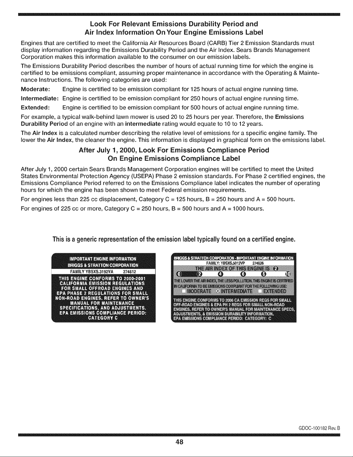
Look For Relevant Emissions Durability Period and
Air index information On Your Engine Emissions Label
Engines that are certified to meet the California Air Resources Board (CARB) Tier 2 Emission Standards must
display information regarding the Emissions Durability Period and the Air Index. Sears Brands Management
Corporation makes this information available to the consumer on our emission labels.
The Emissions Durability Period describes the number of hours of actual running time for which the engine is
certified to be emissions compliant, assuming proper maintenance in accordance with the Operating & Mainte-
nance Instructions. The following categories are used:
Moderate: Engine is certified to be emission compliant for 125 hours of actual engine running time.
Intermediate: Engine is certified to be emission compliant for 250 hours of actual engine running time.
Extended: Engine is certified to be emission compliant for 500 hours of actual engine running time.
For example, a typical walk-behind lawn mower is used 20 to 25 hours per year. Therefore, the Emissions
Durability Period of an engine with an intermediate rating would equate to 10 to 12 years.
The Air index is a calculated number describing the relative level of emissions for a specific engine family. The
lower the Air Index, the cleaner the engine. This information is displayed in graphical form on the emissions label.
After July 1,2000, Look For Emissions Compliance Period
On Engine Emissions Compliance Label
After July 1, 2000 certain Sears Brands Management Corporation engines will be certified to meet the United
States Environmental Protection Agency (USEPA) Phase 2 emission standards. For Phase 2 certified engines, the
Emissions Compliance Period referred to on the Emissions Compliance label indicates the number of operating
hours for which the engine has been shown to meet Federal emission requirements.
For engines less than 225 cc displacement, Category C = 125 hours, B = 250 hours and A = 500 hours.
For engines of 225 cc or more, Category C = 250 hours, B = 500 hours and A = 1000 hours.
This is a generic representation of the emission label typically found on a certified engine.
FAMILYYBSXS.3192VA 274812
GDOC-100182Rev.B
48
Congratulations on making a smart purchase. Your new Craftsman® product is designed and
manufactured for years of dependable operation. But like all products, it may require repair
from time to time. That's when having a Repair Protection Agreement can save you money and
aggravation.
Here's what the Repair Protection Agreement* includes:
[] Expert service by our 10,000 professional repair specialists
[] Unlimited service and no charge for parts and labor on all covered repairs
[] Product replacement up to $1500 if your covered product can't be fixed
[] Discount of 25% from regular price of service and related installed parts not covered by the
agreement; also, 25% off regular price of preventive maintenance check
[] Fast help by phone - we call it Rapid Resolution - phone support from a Sears representative.
Think of us as a "talking owner's manual."
Once you purchase the Repair Protection Agreement, a simple phone call is all that it takes for you
to schedule service. You can call anytime day or night, or schedule a service appointment online.
The Repair Protection Agreement is a risk-free purchase. If you cancel for any reason during the
product warranty period, we will provide a full refund. Or, a prorated refund anytime after the
product warranty period expires. Purchase your Repair Protection Agreement today!
Some limitations and exclusions apply. For prices and additional information in the U.S.A.
call 1=800=827=6655.
*Coverage in Canada varies on some items. For full details call Sears Canada at 1=800=361=
6665.
Sears Installation Service
For Sears professional installation of home appliances, garage door openers, water heaters, and
other major home items, in the U.S.A. or Canada call 1=800=4=MY=HOME®.
49
Declaraci6n de garantia ............................ Pagina 50
Practicas operaci6n seguras ..................... Pagina 51
Montaje ...................................................... Pagina 55
Operaci6n .................................................. Pagina 61
Servicio y Mantenimiento .......................... Pagina 65
Almacenamiento fuera de temporada ....... Pagina 73
Soluci6n de problemas .............................. Pagina 74
Acuerdo de protecci6n para reparaciones .... Pagina 79
Lista de piezas ........................................... Pagina 28
NOmero de servicio ................................... Cubierta
posterior
GARANTiA COMPLETA CRAFTSMAN POR DOS AltOS
PORDOSANOSapartir dela fechade la cornpra,este productoest,.garantizadopordefectosen los rnaterialesy la rnanodeobra.
Los productosdefectuososser_.nreparadossin costoo reernplazadossin costosi la reparaci6nno est,. disponiNe.
La presentegarantiase anula si se utilizaeste productoalgunavezparaprestarservicioscornercialeso si se Ioalquilaa otra persona.
Paraobtener informaci6nsobre el alcance de la garantiay solieitar la reparaci6no el reemplazo,visite el sitio Web: www.craftsman.com
Esta garantia cubre0NICAMENTElosdefectos en los rnaterialesy en la rnano de obra. Esta garantia NOcubre:
• Elernentosno renovablesque puedendesgastarsepor eluso normal,duranteel plazodela garantia,incluyendoentreotros,las barrenas,
las paletasde las barrenas,los cortadoresde desplazarniento,laszapatasantideslizantes,la placade raspado,lospasadoresdecuchilla,
la bujia,elfiltrode aire,las correasy el filtrodeaceite.
• Serviciosde rnantenirnientoest_.ndar,carnbiosde aceiteo afinaci6n.
• Carnbiode neurn_.ticoso reparacionespor pinchadurascon objetosexternoscornoclavos,espinas,toconeso vidrios.
• Reernplazoo reparaci6nde neurn_.ticoso ruedascornoresultadodel desgastenormal,unaccident&o funcionarniento
o rnantenirnientoincorrectos.
• Reparacionesrequeridascornoresultadodel uso inadecuadopot partedeloperador,incluyendoentreotrosel da_oocasionadoporobjetos
queirnpactanla rn_.quinay que tuercenel bastidor,el ejede labarrena,etc., o debido a queel motorrueaceleradoen exceso.
• Reparacionesnecesariasdebidoa negligenciadeloperador,incluyendoentre otros,da_osrnec_.nicoy el_ctricoocasionadopor
unalrnacenarnientono apropiado,fallaporel uso de aceitede gradoy/o cantidadnoapropiadoso falla por no dar rnantenirniento
alequipo de acuerdocon las instruccionescontenidasenel manualdel operador.
• Lirnpiezao reparacionesdel motor(sisternade combustible)debidasa combustibleque se deterrninaest,. contarninadou oxidado(viejo).
Engeneral,el combustibledebeutilizarseen unperiodono mayorde 30dias a partirde su adquisici6n.
• Eldeterioroy desgastenormalde losacabadosexteriores,o reernplazode laetiquetadelproducto.
Estagarantialeotorgaderechoslegalesespecificos,pero ustedpodriagozarde otrosderechosen raz6nde su lugarde residencia.
Sears Brands Management Corporation, Hoffman Estates, IL 60179
Tipodeaceite del motor:
Capacidadde aceitedel motor:
Capacidadde combustible:
Bujias:
Separaci6nde las bujias:
5W-30
20 onzas
2.3 cuartos
F6RTC
.020" a .030"
N_mero de rnodelo ..........................................................
N_mero de sede ..............................................................
Feehade eompra .............................................................
Registrearribael nOrnerodel rnodelo,el nOrnerode seriey la fecha
de cornpra
© KCD IP,LLC
50
Lapresenciade este sfrnboloindicaque setratade instrucciones
irnportantesde seguridadque se debenrespetarpara evitar
poneren peligrosu seguridadpersonaly/o materialy la de otras
personas.Lea y siga todaslas instruccionesdeestemanualantes
de poneren funcionarnientoestarn_.quina.Si no respetaestas
instruccionespodrfaprovocarlesionespersonales.Cuandoveaeste
sfrnbolo,i presteatenci6na la advertencia!
PROPOSICION 65 DE CALIFORNIA
Elescapedel motordeesteproducto,algunosde suscornponentes
y algunoscornponentesdelvehfculocontieneno liberansustancias
qufrnicasque el estadodeCaliforniaconsideraque puedenproducir
c_.ncer,defectosde nacirnientou otros problernasreproductivos.
Estarn_.quinarueconstruidapara seroperadadeacuerdocon
las reglasde seguridadcontenidasen este manual.AI igualque
concualquiertipo deequipo rnotorizado,undescuidoo errorpor
partedeloperadorpuedeproducirlesionesgraves.Estarn_.quina
es capazde arnputarrnanosy piesy dearrojarobjetoscon gran
fuerza.Deno respetarlas instruccionesde seguridadsiguientesse
puedenproducirlesionesgraveso la rnuerte.
Su responsabilidad--Restrinja el usode estarn_.quina
rnotorizadaalas personasque lean,cornprendany respetenlas
advertenciase instruccionesqueaparecenen estemanualyen la
rn_.quina.
iGUARDEESTASINSTRUCCIONES!
CAPACITACI6N
• Lea,entienday curnplatodaslas instruccionesincluidasen
la rn_.quinayen los rnanualesantes de rnontarlay utiNzarla.
Guardeestemanualenun lugarseguroparaconsultasfuturasy
peri6dicas,asf cornopara solicitarrepuestos.
• Leael Manualdel Operadory sigatodaslas advertenciase
instruccionesde seguridad.Elfracasode hacerasf puedecausar
la heridaseriaal operadory/o personaspresentes.
• Farniliarfcesecontodoslos controlesy con el usoadecuado
delos rnisrnos.Sepa c6rnodetenerlarn_.quinay desactivarlos
controlesr_.pidarnente.
• No perrnitanuncaque los ni_osrnenoresde 14a_osutilicen
estarn_.quina.Los ni_osde 14a_osen adelantedebenleer y
entenderlas instruccionesde operaci6ny norrnasdeseguridad
contenidasen este manual,yen la rn_.quinaydebenser entrena-
dosy supervisadosporun adulto.
• Nuncaperrnitaque los adultosoperenestarn_.quinasin recibir
antesla instrucci6napropiada.
• Losobjetosarrojadospor la rn_.quinapuedenproducirlesiones
graves.Planifiqueel patr6nenel queva air arrojandonievepara
evitarque ladescargade materialse realicehacialos carninos,
los observadores,etc.
• Mantengaa losobservadores,ayudantes,rnascotasy ni_ospor
Io rnenosa 75piesde la rn_.quinarnientrasla rnisrnaest,.en
funcionarniento.Detengala rn_.quinasi alguienseacerca.
• Seaprecavidopara evitarpatinarseo caerseespecialrnente
cuandoopera la rn_.quinaen reversa.
PR E PA RATIVO S
Inspeccionerninuciosarnenteel _.readondeutilizar_,el equipo.Saque
todoslos felpudos,peri6dicos,trineos,tablas,cablesy otros objetos
extra_oscon los que podrfatropezaro quepodrfanser arrojadospor
labarrena/irnpulsor.
• Paraprotegerselosojos utilicesiernpreanteojosoantiparras
de seguridadrnientrasoperala rn_.quinao rnientrasla ajusta
o repara.Losobjetosarrojadosquerebotanpuedenproducir
lesionesocularesgraves.
• Noopere la rn_.quinasin la vestirnentaadecuadaparaestaral
airelibre en invierno.No utilicealhajas,bufandaslargasu otras
prendassueltasquepodrfanenredarseen las partesrn6viles.
UtiNceun calzadoespecialpara superficiesresbaladizas.
• Useun prolongadory untornacorrientedetrescablescon
conexi6na tierraparatodaslas rn_.quinascon rnotoresde
encendidoel_ctrico.
• Ajustela alturade lacaja del tornacorrienteparaNrnpiarla grava
o las superficiescon piedrastrituradas.
• Desengranetodaslas palancasde controlantesde arrancarel
motor.
• Nuncaintenterealizarajustesrnientrasel motorest,.en rnarcha
exceptoen los casosespecfficarnenterecornendadosen el
manualdel operador.
• Dejeque el motor y la rn_.quinase adaptena laternperatura
exteriorantesde cornenzara sacarla nieve.
51
Manejo seguro de la gasolina
Paraevitarlesionespersonales0 daSosrnaterialestengarnucho
cuidadocuandotrabajecon gasolina.Lagasolinaes surnarnente
inflarnabley susvaporespuedencausarexplosiones.Si se derrarna
gasolinaencirna0 sobrela ropa se puedelesionargravernenteya que
se puedeincendiar. L&vesela piely c&rnbiesede ropade inrnediato.
• Utilices610los recipientespara gasolinaautorizados.
• Apaguetodoslos cigarrillos,cigarros,pipasy otras fuentesde
cornbusfi6n.
• Nuncacarguecombustibleen larn&quinaen unespaciocerrado.
• Nuncasaquela tapadelcombustibleni agreguecombustible
rnientrasel motorest&caliente0 en rnarcha.
• Dejequeel motorse enfriepor I0 rnenosdos rninutosantesde
volvera cargarcombustible.
• Nuncalleneen excesoel dep6sitodecombustible.Lleneel
tanquea no rn&sde1/2pulgadapordebajode la basedel cuello
de Ilenadodejandoespacioparala dilataci6ndeIcombustible.
• Vuelvaa colocarla tapade la gasoiinay aj_stelabien.
• Lirnpieel combustibleque se hayaderrarnadosobreel motory el
equipo.Trasladela rn&quinaa otra zona.Espere5 rninutosantes
deencenderel motor.
• Nuncaalrnacenela rn&quina0 el recipientede combustibleen
unespaciocerradodondehayafuego,chispas0 luz piloto(por
ejernplo,hornos,calentadoresdeagua,calefactores,secadores
de ropa,etc.).
• Dejequela rn_.quinase enfrieporIo rnenos5 rninutosantesde
guardarla.
• NuncaIlenelos recipientesenel interiordeunvehiculoo carni6n
ocaja de rernolquecon recubrirnientospl_.sticos.Coloque
siernprelos recipientesen el pisoy lejosdelvehiculoantesde
Ilenarlos.
• Sies posible,retireel equipoa gasolinadelcarni6no rernolque
y II_neloen el suelo.Siestonoes posible,Ileneel equipoen un
rernolquecon contenedorport_.til,en vez dedesdeunaboquilla
dispensadoradegasolina.
• Mantengala boquilladispensadoraen contactocon el hordedel
dep6sitode combustibleo con la aberturadel recipienteentodo
rnornento,hastaterrninarla carga.No utiliceundispositivode
apertura/cierrede boquilla.
FUNCIONANIIENTO
• No pongalas rnanoso los piescerca de las piezasrotatorias,
en lacajade la barrena/ irnpulsoro en el rnontajedel canalde
descarga.Hacercontactocon piezasgiratoriaspuederesultaren
laarnputaci6nde rnanoso pies.
• La palancadecontrolde la barrena/ irnpulsores un dispositivo
de seguridad.Nuncaevite su funcionarniento.De hacerlola
operaci6nde la rn_.quinaes riesgosay puedeocasionarlesiones.
• Las palancasde control debenfuncionarbienen arnbasdirec-
cionesy regresarautorn_.ticarnentea la posici6nde desengrane
cuandose lassuelta.
• Nuncaoperela rn_.quinasi faltaunrnontajedelcanalo si el
rnisrnoest,. daSado.Mantengatodoslosdispositivosde seguri-
daden su lugaryen funcionarniento.
• Nuncaenciendaelmotor en espacioscerradoso en una zona
con pocaventilaci6n.El escapedel motorcontienernon6xidode
carbono,ungas inodoroy letal.
• Noutilice la rn_.quinabajo la influenciadelalcoholo las drogas.
• El silenciadory el motorse calientany puedencausarquernadu-
ras.Nolos toque.Mantengaa los niSosalejados.
• Seasurnarnenteprecavidocuandooperela rn_.quinasobreuna
superficiecon gravaocuandola cruce.Mant_ngasealerta porsi
se presentanpeligrosocultoso tr_.nsito.
• Tengacuidadocuandocarnbiede direcci6no cuandoopere
la rn_.quinaenpendientes.Nouse la rn_.quinaen pendientes
pronunciadas.
• Planifiqueel patr6nenel queva a ir arrojandonieveparaevitar
que ladescargade materialse produzcahacialas ventanas,
las paredes,losautorn6viles,etc.y evitarasi posiblesdaSos
rnaterialeso lesionesproducidaspor los rebotes.
• Nuncadirija la descargahacialos niSos,los observadoreso las
rnascotasni dejequenadiese pare delantede la rn_.quina.
• Nosobrecarguela capacidadde la rn_.quinatratandode sacarla
nievernuyr_.pidarnente.
• Nuncaopereesta rn_.quinasin buenavisibilidado ilurninaci6n.
Siernpredebeestar segurode queest,.bienafirrnadoy su-
jetandofirrnernentelas rnanijas.Carnine,nuncacorra.
• Cortela corrientea la barrena/ irnpulsorcuandotransportela
rn_.quinao cuandolarnisrnanoest,.en uso.
• Nuncaoperela rn_.quinaa alta velocidadde desplazarniento
sobresuperficiesresbaladizas.Mirehaciaabajoy haciaatr_.sy
tengacuidadocuandovayarnarchaatr_.s.
• Si la rn_.quinacornenzaraavibrarde rnaneraanorrnal,detengael
motor,desconecteel cablede labujiay p6ngalade rnaneraque
hagarnasacontrael motor.Inspeccionela rn_.quinarninuciosa-
rnenteparaver si est,.daSada.Reparetodos los daSosantesde
encendery operarla rn_.quina.
• Desengranetodas las palancasde controly detengaelmotor
antesde dejar la posici6nde operaci6n(detr_.sde las rnanijas).
Esperea que labarrena/ irnpulsorse detengaporcornpleto
antesde destaparel rnontajedelcanalo realizarajustese
inspecciones.
• Nuncapongalas rnanosen las aberturasdedescargao de
recolecci6n.Utilicesiernprela herrarnientade lirnpiezaquese
adjuntaparadestaparla aberturadedescarga.Nodestapeel
rnontajedel canal rnientrasel motorest,.en funcionarniento.
Antesde destaparlo,apagueel motory perrnanezcadetr_.sde las
rnanijashastaque todaslas partes rn6vilesse hayandetenido.
• Uses61ounionesy accesoriosaprobadospor el fabricante(por
ejernplo,pesaspara las ruedas,cadenasparalos neurn_.ticos,
cabinas,etc.).
52
• Paraencenderel motor,jale de lacuerdalentarnentehastaque
sientaresistencia,luegojale r_.pidarnente.Elreplieguer_.pidode
la cuerdade arranque(tensi6nde retroceso)le jalar_,la rnanoy
el brazohaciael motorrn_.sr_.pidodeIo queusted puedesoltar.
El resultadopuedenserhuesosrotos,fracturas,hernatornaso
esguinces.
• Si se presentansituacionesqueno est_.nprevistasen este
manual,seacuidadosoy use el sentidocornOn.
• Porrazonesde seguridaddentrode lagarantia,operaci6no
rnantenirnientode las preguntas,o parapedirpiezasy el servicio
dehorario,Ilarneal 1-800-4-MY-HOME.
MANTENIMIENTO Y ALMACENAMIENTO
• Nuncaalterelos dispositivosde seguridad.Controleperi6dica-
rnenteque funcionencorrectarnente.Rernitasealas secciones
demantenirnientoy ajustede este manual.
• Antesde realizarla lirnpieza,repararo revisarla rn_.quina,
desengranetodas laspalancasdecontroly detengael motor.
Esperea quela barrena/ irnpulsorse detengapor cornpleto.
Desconecteel cabledela bujfay p6ngalohaciendornasacontra
el motorparaevitarquese enciendaaccidentalrnente.
• Controlefrecuenternentequetodos lospernosy tornillosest_n
bienajustadosparacornprobarque la rn_.quinase encuentra
encondicionessegurasde funcionarniento.Adern_.s,hagauna
inspecci6nvisual de larn_.quinaparaverificarsi est,.da_ada.
• No carnbielaconfiguraci6ndel reguladordel motorni acelere
dernasiadoel rnisrno.El reguladordelmotorcontrolala velocidad
rn_.xirnaseguradefuncionarnientodelmotor.
• Las placasde raspadoy las zapatasantideslizantesquese
usancon la rn_.quinaquitanievese desgastany se da_an.
Paraprotegersu seguridad,verifiquefrecuenternentetodos los
cornponentesy reernpl_.celoss61ocon partesde los fabricantes
deequiposoriginales(OEM).iEI usode piezasqueno curnplen
con lasespecificacionesdel equipooriginalpuederesultaren
rendirnientoinadecuadoadern_.sde poneren riesgola seguridad!
• Reviselas palancasde controlperi6dicarnentepara verificar
queengraneny desengranenadecuadarnentey ajOstelossi es
necesario.Consultela secci6nde ajustesdeeste manualdel
operadorparaobtenerinstrucciones.
• Mantengao reernplacelasetiquetasde seguridade instrucciones
segQnseanecesario.
• Respetelas norrnasreferentesa ladisposici6ncorrectay las
reglarnentacionessobregasolina,aceite,etc. paraprotegerel
medicarnbiente.
• Antesdealrnacenarlarn_.quinaenci_ndalaunosrninutospara
sacarla nievequehayaquedadoen larnisrnay paraevitarasi
quese congelela barrena/irnpulsor.
• SegOnla Cornisi6nde Seguridadde Productosparael Consurni-
dorde los EstadosUnidos(CPSC)y laAgenciade Protecci6n
Arnbientalde los EstadosUnidos(EPA),este productotieneuna
vida Qtilmediadesiete (7) a_os, 6 60 horasdefuncionarniento.
AI finalizarla vida Otilmedia,adquieraunarn_.quinanuevao
hagainspeccionaranualrnente_stapor un distribuidordeservicio
autorizadoparacerciorarsede quetodoslos sisternasrnec_.nicos
y deseguridadfuncionancorrectarnentey notienenexcesivo
desgaste.Si no Iohace, puedenproducirseaccidentes,lesiones
o rnuerte
• Nuncaalrnacenela rn_.quinao el recipientede combustibleen un
espaciocerradodondehayafuego,chispaso luz pilotocornopor
ejernplo,calentadoresde agua,hornos,secadoresde ropa,etc.
• Consultesiernpreel manualdel operadorparaobtener
instruccionesadecuadaspara elalrnacenarnientofuerade
ternporadaVerifiquefrecuenternentelaIfneade combustible,el
tanque,el tap6n,y losaccesoriosbuscandorajaduraso perdidas.
Reernplacede ser necesario.
• Nod_ arranqueal motorsi noest,. labujiade encendido.
NO MODIFIQUE EL MOTOR
Paraevitarlesionesgraveso larnuerte,nornodifiqueel motorbajo
ningunacircunstancia.Si carnbiala configuraci6ndel reguladorel
motorpuededescontrolarsey operara velocidadesinseguras.Nunca
carnbielaconfiguraci6ndef_.bricadel reguladordel motor.
AVISO REFERIDO A EMISIONES
Losrnotoresqueest&ncertificadosy curnplencon las regulaciones
de ernisionesfederalesEPAy de Californiapara SORE(Equipos
peque_ostodoterreno)est_.ncertificadosparaoperarcon gasolina
cornOnsinplornoy puedenincluirlossiguientessisternasde control
de ernisiones:Modificaci6ndemotor(EM) y catalizadorde tresvias
(TWO)si est_.nequipadosde esa rnanera.
GUARDACHISPAS
Estarn&quinaest,. equipadacon unmotorde cornbusti6ninternay
nodebe ser utilizadaen o cercade unterrenoagrestecubiertopor
bosque,rnalezaso hierbaexceptosi el sisternade escapedelmotor
est,.equipadocon unarnortiguadorde chispasquecurnplaconlas
leyeslocaleso estatalescorrespondientes,encaso de haberlas.
Sise utilizaun arnortiguadordechispasel operadorIo debernantener
en condicionesde usoadecuadas.Enel Estadode Californialas
rnedidasanteriorrnenternencionadassonexigidaspor ley (Arficulo
4442del C6digode RecursosPOblicosde California).Es posible
queexistanleyessirnilaresen otros estados.Lasleyesfederalesse
aplicanenterritoriosfederales.
Puedeconseguirelarnortiguadorde chispasparael silenciadora
travesde sudistribuidorautorizadode rnotoreso poni_ndoseen
contactocon el departarnentodeservicios.
53
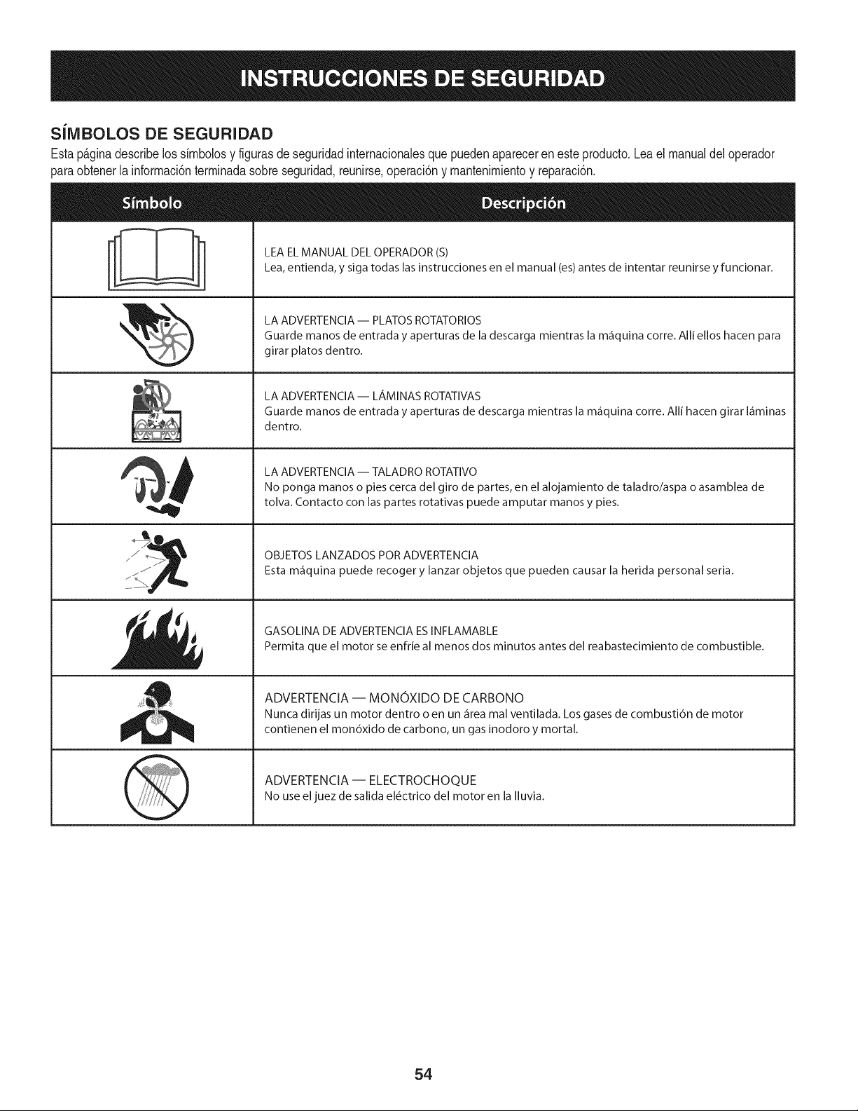
SiMBOLOS DE SEGURIDAD
Estap_ginadescribelossimbolosy figurasde seguridadinternacionalesque puedenaparecereneste producto.Leael manualdel operador
)araobtenerla informaci6nterminadasobreseguridad,reunirse,operaci6ny mantenimientoy reparaci6n.
i
i
LEA EL MANUAL DEL OPERADOR (S)
Lea, entienda, y siga todas las instrucciones en el manual (es) antes de intentar reunirse y funcionar.
LA ADVERTENCIA -- PLATOS ROTATORIOS
Guarde manos de entrada y aperturas de la descarga mientras la m_iquina corre. Alli ellos hacen para
girar platos dentro.
LA ADVERTENCIA- LAMINAS ROTATIVAS
Guarde manos de entrada y aperturas de descarga mientras la m_iquina corre. Alli hacen girar I_iminas
dentro.
LA ADVERTENCIA -- TALADRO ROTATIVO
No ponga manos o pies cerca del giro de partes, en el alojamiento de taladro/aspa o asamblea de
tolva. Contacto con las partes rotativas puede amputar manos y pies.
OBJETOS LANZADOS POR ADVERTENCIA
Esta m_iquina puede recoger y lanzar objetos que pueden causar la herida personal seria.
GASOLINA DE ADVERTENCIA ESINFLAMABLE
Permita que el motor se enfrie al menos dos minutos antes del reabastecimiento de combustible.
ADVERTENCIA -- MONOXIDO DE CARBONO
Nunca dirijas un motor dentro o en un _irea mal ventilada. Los gases de combusti6n de motor
contienen el mon6xido de carbono, un gas inodoro y mortal.
ADVERTENCIA -- ELECTROCHOQUE
No use eljuez de salida el_ctrico del motor en la Iluvia.
54
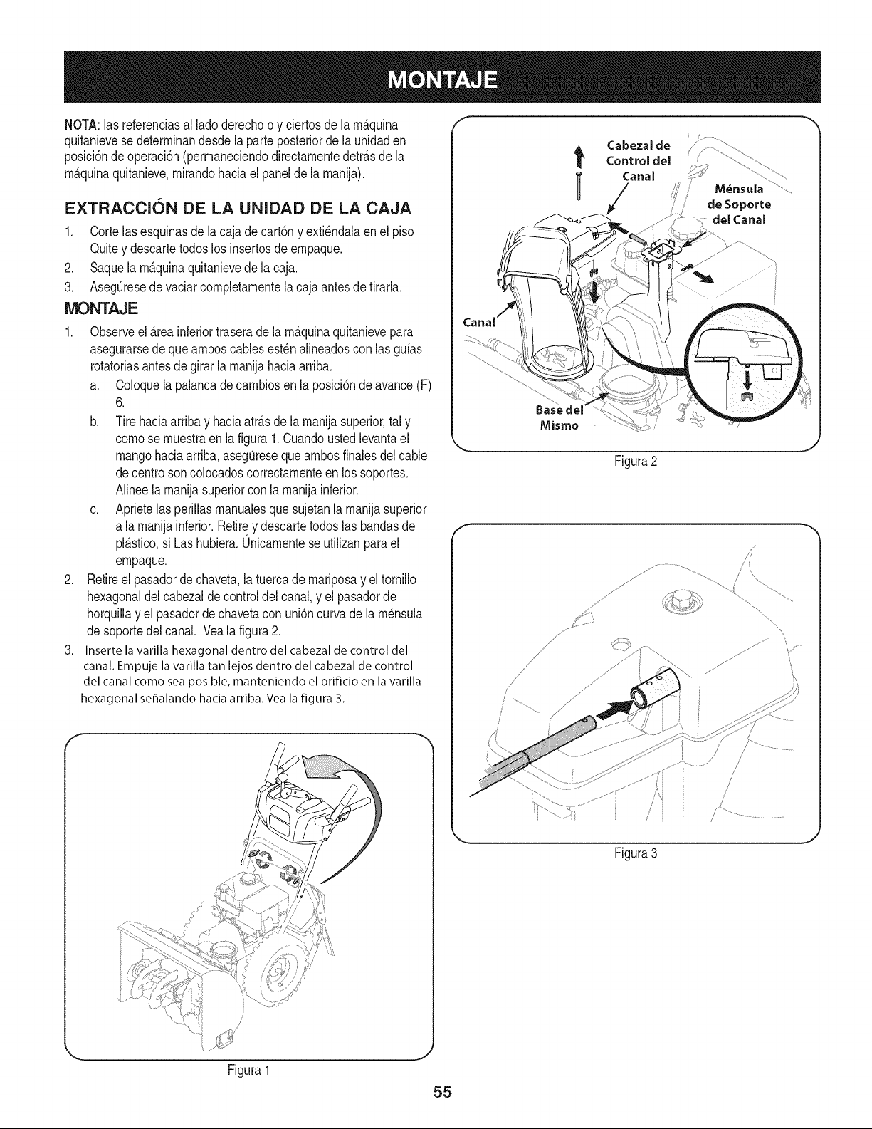
NOTA:las referenciasal ladederechoo y ciertosde la rn_.quina
quitanievese deterrninandesdela parteposteriorde la unidaden
posici6ndeoperaci6n(perrnaneciendodirectarnentedetr_.sde la
rn_.quinaquitanieve,rnirandohaciael panelde la rnanija).
EXTRACCION DE LA UNIDAD DE LA CAJA
1. Corte lasesquinasdela cajade cart6ny exti6ndalaenel piso
Quitey descartetodoslos insertosde ernpaque.
2. Saquela rn_.quinaquitanievede la caja.
3. AsegQresede vaciarcornpletarnentela cajaantesde tirarla.
MONTAJE
1. Observeel _.reainferiortraserade la rn_.quinaquitanievepara
asegurarsede quearnboscablesest6n alineadoscon las guias
rotatoriasantes de girarla rnanijahaciaarriba.
a. Coloquela palancadecarnbiosen la posici6ndeavance(F)
6.
b. Tirehaciaarriba y haciaatr_.sde larnanijasuperior,tal y
comese rnuestraen la figura1.Cuandoustedlevantael
mangohaciaarriba,asegQresequearnbosfinalesdel cable
decentre soncolocadoscorrectarnenteen lossoportes.
Alineela rnanijasuperiorconla rnanijainferior.
c. Aprietelas perillasrnanualesque sujetanla rnanijasuperior
a larnanijainferior.Retirey descartetodos las bandasde
pl_.stico,si Las hubiera.0nicarnentese utilizanpara el
ernpaque.
2. Retireel pasadorde chaveta,la tuercade rnariposay eltornillo
hexagonaldel cabezaldecontroldelcanal,y el pasadorde
horquillay el pasadordechavetacon uni6ncurva de larn6nsula
desoportedel canal. Veala figura2.
3. Inserte la varilla hexagonal dentro del cabezal de control del
canal. Empuje la varilla tan lejos dentro del cabezal de control
del canal come sea posible, manteniendo el orificio en la varilla
hexagonal se_alando hacia arriba. Vea la figura 3.
de Soporte
del Canal
Baseclel
Misme
Figura2
f
.......,/
\\
Figura3
Figura1
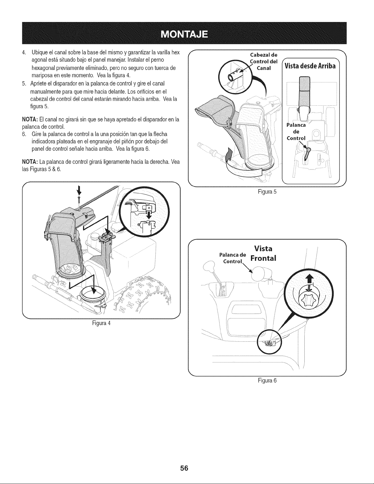
4. Ubiqueelcanalsobrelabasedelmismoygarantizarlavarillahex
agonalest,.situadobajoelpanelmanejar.Instalarelperno
hexagonalpreviamenteeliminado,peronosegurocontuercade
mariposaenestemomento.Vealafigura4.
5. Aprieteeldisparadorenlapalancadecontrolygireelcanal
manualmenteparaquemirehaciadelante.Losorificiosenel
cabezaldecontroldelcanalestar_.nmirandohaciaarriba.Veala
figura5.
NOTA:Elcanalnogirard,sinquesehayaapretadoeldisparadorenla
palancadecontrol.
6. Girelapalancadecontrolalauna)osici6ntanquelaflecha
indicadoraplateadaenelengranajedelpii6npordebajodel
paneldecontrolseSalehaciaarriba.Vealafigura6.
NOTA:Lapalancadecontrolgirard,ligeramentehacialaderecha.Vea
lasFiguras5&6.
_, ,J
Figura4
f
Control
Figura5
f
Vista
Figura6
56
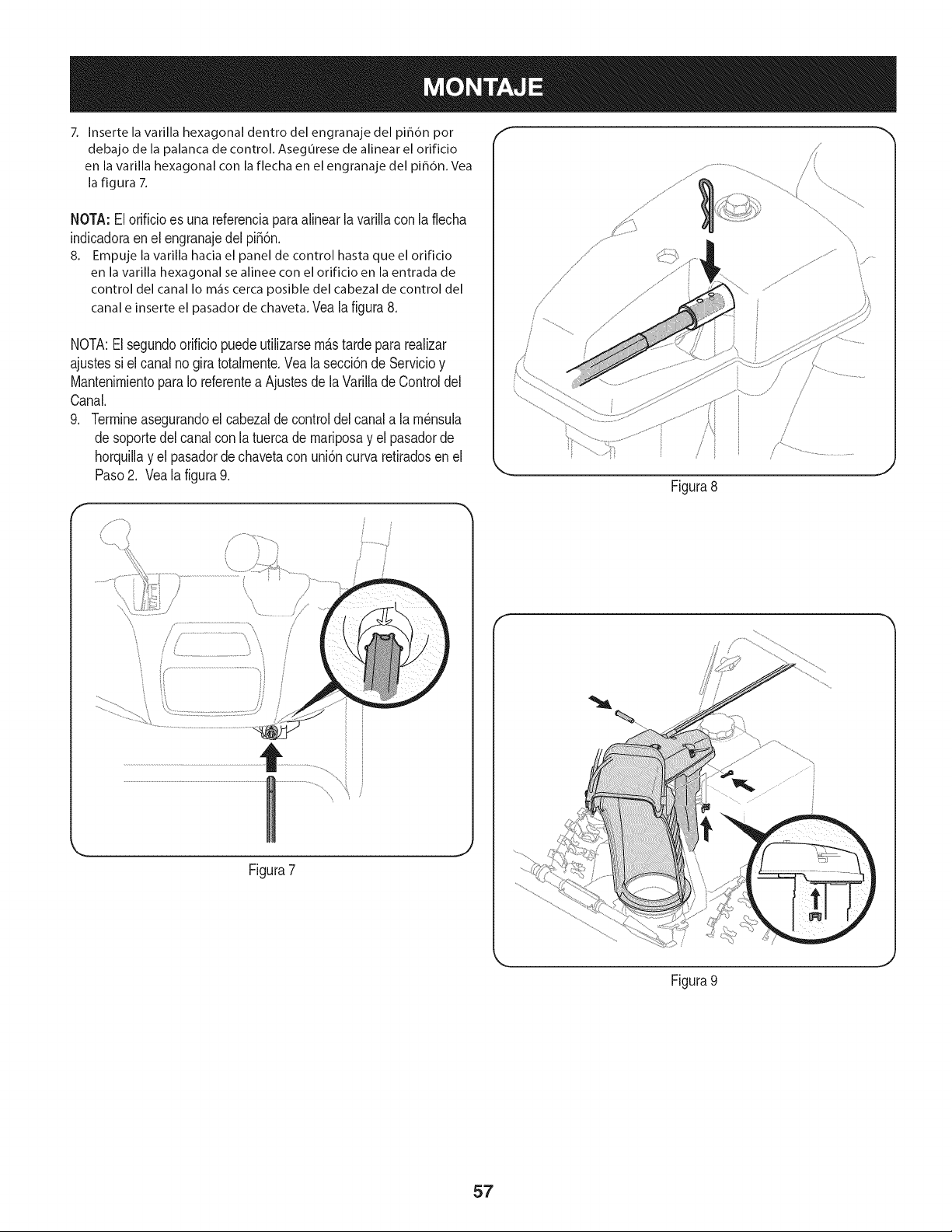
7. Inserte la varilla hexagonal dentro del engranaje del pih6n por
debajo de la palanca de control. Asegurese de alinear el orificio
en la varilla hexagonal con la flecha en el engranaje del piB6n. Vea
la figura 7.
NOTA:El orificioes unareferenciaparaalinear la varillacon laflecha
indicadoraen el engranajedel pi56n.
8. Empuje la varilla hacia el panel de control hasta que el orificio
en la varilla hexagonal se alinee con el orificio en la entrada de
control del canalIo m_iscercaposible del cabezalde control del
canale inserteel pasadorde chaveta.Veala figura8.
NOTA:El segundoorificiopuedeutilizarsem&stardeparareaNzar
ajustessi el canalno gira totalmente.Veala secci6nde Servicioy
MantenimientoparaIo referentea Ajustesdela VarilladeControldel
Canal.
9. Termineasegurandoel cabezaldecontroldel canala lam_nsula
desoportedel canalcon la tuercade mariposay el pasadorde
horquillay el pasadordechavetacon uni6ncurva retiradosen el
Paso2. Vea la figura9.
r
/
/
/ / ...............................'_ i
Figura7
/
/
Figura8
Figura 9
./
J
57
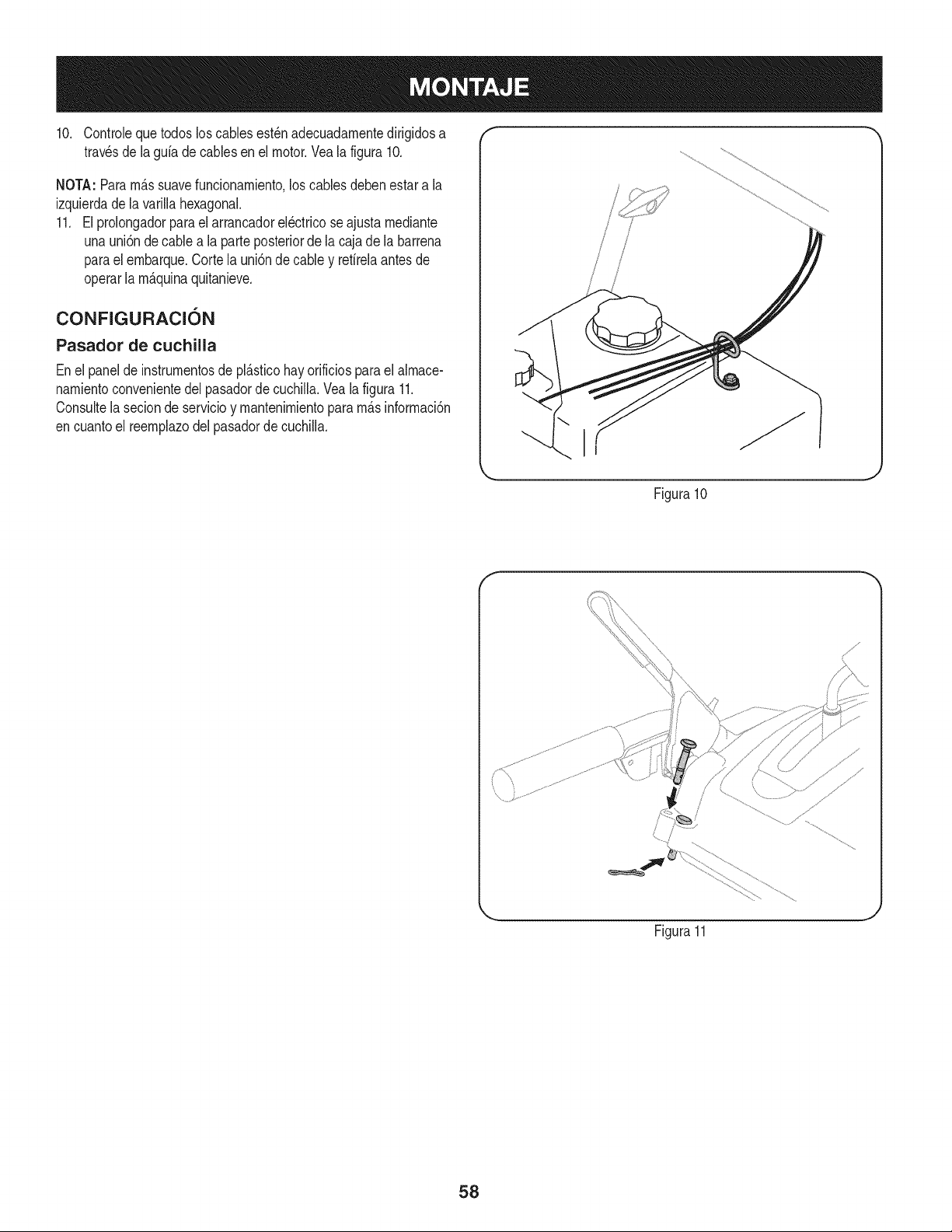
10. Controlequetodos loscablesest_nadecuadarnentedirigidosa "" ""
travesde lagufa decablesen el motor.Veala figura10.
NOTA:Pararn_.ssuavefuncionarniento,loscables debenestara la
izquierdade lavarillahexagonal.
11. El prolongadorparael arrancadorel_ctricoseajustarnediante
unauni6nde cablea la parteposteriorde lacaja de la barrena
parael ernbarque.Cortela uni6ndecabley refirelaantesde
operarla rn_.quinaquitanieve.
CONFIGURACI6N
Pasador de cuchilla
Enel panelde instrurnentosde pl_.sticohayorificiosparael alrnace-
narnientoconvenientedel pasadordecuchilla.Veala figura 11.
Consultela secionde servicioy rnantenirnientopara rn_.sinforrnaci6n
encuantoel reernplazodel pasadordecuchiNa.
Figura10
f
Figura11
58
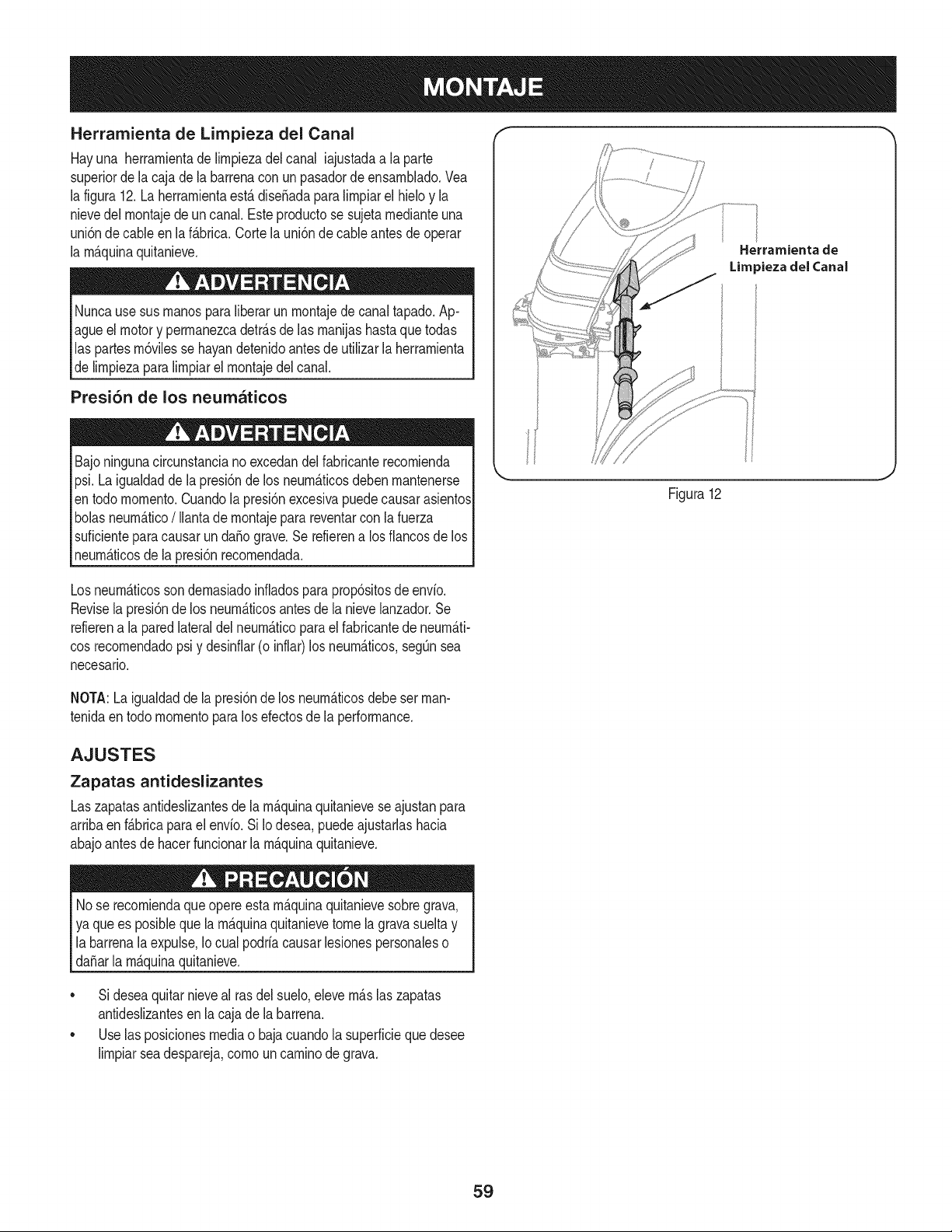
Herramienta de Limpieza del Canal
Hayuna herrarnientade Nrnpiezadel canal iajustadaa la parte
superiorde lacaja dela barrenaconun pasadordeensarnNado.Vea
la figura12.La herrarnientaest,.diseSadaparaNrnpiarel hMo y la
nievedel rnontajede un canal.Esteproductose sujetarnedianteuna
uni6nde cableen la f_.brica.Corte launi6nde cableantesdeoperar
la rnAquinaquitanieve.
Nuncause sus rnanosparaNberarun rnontajede canaltapado.Ap-
agueel motory perrnanezcadetr_.sde las rnanijashastaque todas
las partesrn6vNesse hayandetenidoantes deutiNzarla herrarnienta
delirnpiezaparalirnpiarel rnontajedel canal.
Presi6n de los neumaticos
Bajoningunacircunstanciano excedandelfabricanterecornienda
psi.La igualdadde lapresi6nde los neurn_.ticosdebenrnantenerse
entodo rnornento.Cuandolapresi6nexcesivapuedecausarasientos
bolasneurn_.tico/ Ilantadernontajepara reventarcon lafuerza
suficienteparacausarun da_o grave.Serefierena los fiancosde los
neurn_.ticosde la presi6nrecornendada.
Herrarnienta de
Limpiezadel (;anal
Figura12
Losneurn_.ticossondernasiadoinfladosparaprop6sitosde envfo.
Revisela presi6nde los neurn_.ticosantes de la nievelanzador.Se
refierena la paredlateraldel neurn_.ticoparael fabricantede neurn_.ti-
cosrecornendadopsi y desinfiar(o inflar)los neurn_.ticos,segOnsea
necesario.
NOTA:Laigualdadde la presi6nde los neurn_.ticosdebe set rnan-
tenidaentodo rnornentopara los efectosde la performance.
AJUSTES
Zapatas antideslizantes
Laszapatasantideslizantesde la rn_.quinaquitanieveseajustanpara
arribaen f_.bricaparael envfo.Si Io desea,puedeajustarlashacia
abajoantesde hacerfuncionarla rn_.quinaquitanieve.
Nose recorniendaque opereestarn_.quinaquitanievesobregrava,
ya que es posiblequela rn_.quinaquitanievetome la gravasuelta y
labarrenala expulse,Iocual podrfacausar lesionespersonaleso
da_arla rn_.quinaquitanieve.
• Sideseaquitarnieveal rasdel suelo,elevern_.slaszapatas
antideslizantesen la cajade la barrena.
• Uselas posicionesmediao bajacuandola superficieque desee
lirnpiarseadespareja,cornouncarninodegrava.
59
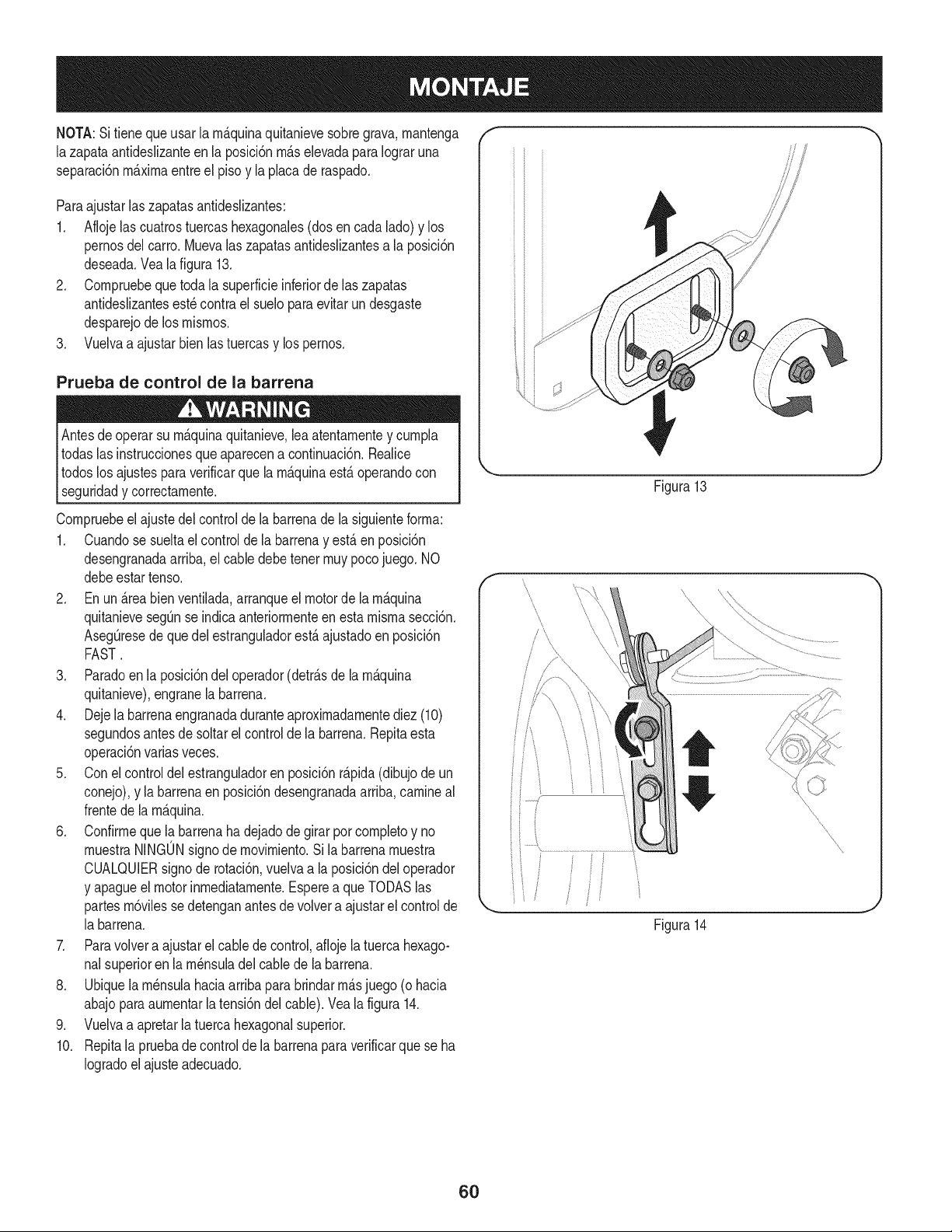
NOTA:Sitieneque usar la rn_.quinaquitanievesobregrava,rnantenga
lazapata antideslizanteen la posici6nrn_.selevadaparaIograruna
separaci6nrn_.xirnaentreel pisoy lapbca de raspado.
Paraajustarlaszapatasantideslizantes:
1. Aflojelas cuatrostuercashexagonales(dosencada lado)y los
pernosdel carro.Muevalas zapatasantideslizantesa la posici6n
deseada.Veala figura 13.
2. Cornpruebequetoda la superficieinferiorde laszapatas
antideslizantesest_contra el sueloparaevitarun desgaste
desparejode los rnisrnos.
3. Vuelvaa ajustarbienlastuercasy lospernos.
Prueba de control de la barrena
Antesde operarsu rn_.quinaquitanieve,leaatentarnentey curnpla
todaslas instruccionesque aparecena continuaci6n.Realice
todoslos ajustespara verificarquela rn_.quinaest,. operandocon
lsegur dad y correctarnente.
Cornpruebeel ajustedel controlde la barrenade la siguienteforrna:
1. Cuandose sueltael controlde la barrenay est,.en posici6n
desengranadaarriba,el cabledebetenet rnuypocojuego. NO
debeestartenso.
2. En un Areabienventilada,arranqueel motorde la rn_.quina
quitanievesegOnse indicaanteriorrnenteen estarnisrnasecci6n.
AsegOresedeque del estrangubdorest,.ajustadoenposici6n
FAST.
3. Paradoen la posici6ndel operador(detr_.sde la rn_.quina
quitanieve),engranela barrena.
4. Dejela barrenaengranadaduranteaproxirnadarnentediez (10)
segundosantesde soltarel controlde la barrena.Repitaesta
operaci6nvarias veces.
5. Conel controldelestranguladoren posici6nr_.pida(dibujode un
conejo),y la barrenaenposici6ndesengranadaarriba,carnineal
frentede larn_.quina.
6. Confirrneque la barrenahadejadodegirar por cornpletoy no
rnuestraNINGONsignodemovirniento.Si la barrenarnuestra
CUALQUIERsignode rotaci6n,vuelvaa la posici6ndeloperador
y apagueel motorinrnediatarnente.Esperea queTODASlas
partesrn6vilessedetenganantesde volvera ajustarel controlde
la barrena.
7. Paravolvera ajustarel cablede control,aflojela tuercahexago-
nalsuperioren la rn_nsubdel cablede la barrena.
8. Ubiquela rn_nsulahaciaarribaparabrindarrn_.sjuego (ohacia
abajoparaaurnentarla tensi6ndelcable).Veala figura14.
9. Vuelvaa apretarla tuercahexagonalsuperior.
10. Repitala pruebade controlde la barrenapara verificarquese ha
Iogradoel ajusteadecuado.
f
J
Figura13
f
.............................................................................................
i i
i
Figura14
60
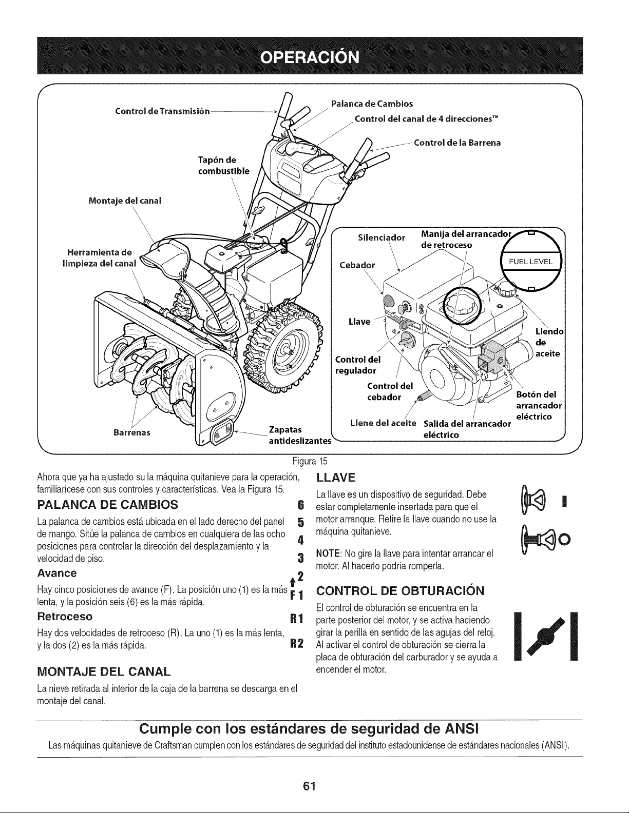
f
Control de Transmisi6n
Palanca de Cambios
Control del canal de 4 direcciones TM
Barrena
Montaje del canal
\
\\
Herramientade
limpiezadelcanal
\
Tap6n de
combustible
\
\
\
Barrenas Zapatas
Silenciador Manija del arrancadol
de retroceso
Cebador \_ _" FUEL LEVEL
Llave
J
Control del
regulador
Control del
cebador
Llene del aceite
Bot6n del
arrancador
r el_ctrico
Salidadela ancador
el_ctrico
Ahoraqueya haajustadosu la mAquinaquitanieveparala operaci6n,
farniliaricesecon suscontrolesy caracterisficas.Vea la Figura15.
PALANCA DE CAMBIOS 6
La palancadecarnbiosest,. ubicadaen el ladoderechodel panel 5
de mango.SitQela palancade carnbiosen cualquieradelas ocho
4
posicionesparacontrolarla direcci6ndeldesplazarnientoy la
velocidadde piso. 3
Avance A 2
Haycinco posicionesdeavance(F). La posici6nuno (1) es la rn_s_ |
lent& y la posici6nseis(6) es la rn_sr_pida.
Retroceso R 1
Haydosvelocidadesde retroceso(R). Launo (1)es la rn_.slenta,
y la dos (2) es la rn_.sr_.pida. R2
Figura15
LLAVE
LaIlavees undispositivode seguridad.Debe
estarcornpletarnenteinsertadaparaque el
motorarranque.Retirela Ilavecuandonouse la
rn_.quinaquitanieve.
NOTE: Nogire la Ilaveparaintentararrancarel
motor.AI hacerlopodriarornperh.
CONTROL DE OBTURACION
Elcontrolde obturaci6nse encuentraen la
parte posteriordel motor,y se activahaciendo
girarla perillaen sentidodelas agujasdel reloj.
AI activarel controlde obturaci6nse cierrala
MONTAJE DEL CANAL
La nieveretiradaal interiorde la cajade labarrenase descargaen el
rnontajedel canal.
.J
placade obturaci6ndel carburadory se ayudaa
encenderel motor.
Curnple con los estandares de seguridad de ANSi
LasrnAquinasquitanievede CraftsmancurnplenconlosestAndaresde seguridaddelinstitutoestadounidensedeestAndaresnacionales(ANSI).
61
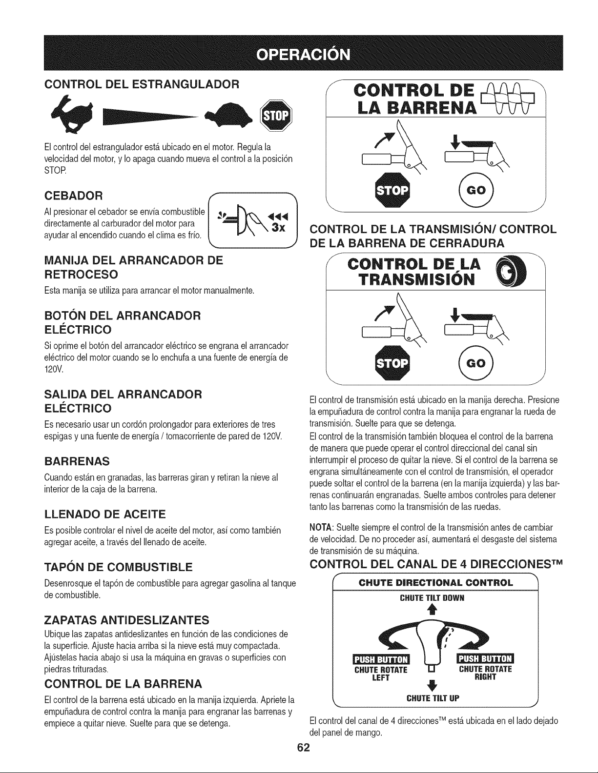
CONTROL DEL ESTRANGULADOR
Elcontroldel estranguladorest,.ubicadoen el motor.Regulala
velocidaddel motor,y Io apagacuandornuevael controla la posici6n
STOP.
CEOAOOR
AI.presionarel cebadorse enviacombustible ,_ '9<_
dlrectarnenteal carburadordelmotor para 3}[
ayudaral encendidocuandoel clirnaes frio.
MANIJA DEL ARRANCADOR DE
RETROCESO
Estarnanijase utilizaparaarrancarel motorrnanualrnente.
BOTON DEL ARRANCADOR
ELECTRICO
Sioprirneel bot6ndelarrancadorel_ctricose engranael arrancador
el_ctricodel motorcuandose Ioenchufaa unafuentede energiade
120V.
SALIDA DEL ARRANCADOR
ELI_CTRICO
Es necesariousar uncord6nprolongadorparaexterioresde tres
espigasy una fuentede energia/ tornacorrientede paredde 120V.
BARRENAS
Cuandoest_.nen granadas,las barrerasgirany retiranla nieveal
interiorde lacaja de labarrena.
LLENADO DE ACEITE
Es posiblecontrolarel niveldeaceitedel motor,asi cornotarnbi_n
agregaraceite,a travesdel Ilenadode aceite.
TAPON DE COMBUSTIBLE
Desenrosqueel tap6ndecombustiblepara agregargasolinaal tanque
decombustible.
ZAPATAS ANTI DES LIZANTES
Ubiquelas zapatasantideslizantesen funci6nde lascondicionesde
la superficie.Ajustehaciaarriba si la nieveest,.rnuycornpactada.
AjQstelashaciaabajosi usala rn_.quinaen gravaso superficiescon
piedrastrituradas.
CONTROL DE LA BARRENA
Elcontrolde la barrenaest,.ubicadoenla rnanijaizquierda.Aprietela
ernpu_adurade controlcontralarnanijaparaengranarlas barrenasy
ernpiecea quitarnieve.Suelteparaque se detenga.
/-
\
CONTROL DE
LA BARRENA
CONTROL DE LA TRANSMISION/CONTROL
DE LA BARRENA DE CERRADURA
J CONTROL DiE LA
TRANSM|S|ON
Elcontrolde transrnisi6nest,.ubicadoen la rnanijaderecha.Presione
laernpu_adurade controlcontra la rnanijaparaengranarla ruedade
transrnisi6n.Suelteparaque se detenga.
Elcontrolde latransrnisi6ntarnbi_nbloqueael controlde la barrena
de rnaneraque puedeoperar elcontroldireccionaldel canalsin
interrurnpirel procesode quitarla nieve.Si el controlde labarrenase
engranasirnult_.nearnentecon elcontroldetransrnisi6n,el operador
puedesoltarel controlde la barrena(enla rnanijaizquierda)y lasbar-
renascontinuar_.nengranadas.Sueltearnboscontrolesparadetener
tantolas barrenascornola transrnisi6nde las ruedas.
NOTA:Sueltesiernpreel controlde la transrnisi6nantesde carnbiar
de velocidad.Deno procederasi, aurnentar_,el desgastedel sisterna
de transrnisi6nde su rn_.quina.
CONTROL DEL CANAL DE 4 DIRECCIONES TM
CHUTE DiRECTiONAL CONTROL
CHUTE TiLT DOWN
t
CHUTE ROTATE CHUTE ROTATE
LEFT RIGHT
4
CHUTE TiLT UP
k_,,, j
TM
Elcontroldel canalde 4 direcciones est,.ubicadaen ellado dejado
del panelde mango.
62
• Carnbiarla direcci6nen lacual lanievees lanzada,apret6nel
bot6nen lapalancade rnandoy pivotela palancade rnandoa la
derechao a la izquierda.
• Paracarnbiarel _.ngulo/distanciaqu_ nievees lanzada,gire la
palancade rnandoavanzadao haciaatr_.s.
HERRAIVIIENTA DE LIMPIEZA
lNunca usesus rnanosparaliberar un rnontajede canaltapado.AntesI
de destaparlo,apagueel motory perrnanezcadetr_.sde lasrnanijas I
hastaque todas laspartes rn6vilesse hayandetenido, j
La herrarnientade lirnpiezadelcanal est,.ajustadaconvenienternente
a la parteposteriorde lacaja dela barrenacon unpasadorde ensarn-
blado.Si seacurnulannievey hieloen elcanal dedescargadurante
la operaci6n,procedacornose indicaa continuaci6nparalirnpiarde
rnanerasegurael rnontajedel canaly la aberturadelcanal:
1. Suelteel controlde la barrenay el control dela transrnisi6n.
2. Paradetenerel motorsaquelaIlavede encendido.
3. Saquela herrarnientade lirnpiezadel pasadorque la ajustaa la
parteposteriordela cajade la barrena.
4. Use el extrernoconforrnadepala de la herrarnientadelirnpieza
paradesplazary recogerla nievey elhieloque se forrnaroncerca
delconjuntodel canal.
5. Vuelvaa ajustarla herrarnientade lirnpiezaal pasadordeen-
sarnbladoubicadoen la parteposteriorde la cajade la barrena,
insertede nuevola Ilavedeencendidoy enciendaelmotorde la
rn_.quinaquitanieve.
6. Paradoen la posici6ndeloperador(detr_.sdelarn_.quinaquita-
nieve),engraneel controlde la barrenaduranteunossegundospara
elirninarlanieveo elhieloque hayanquedadoenel conjuntodel
canal.
ANTES DE ENCENDER EL MOTOR
Lea,cornprenday sigatodas las instruccionesy advertenciasque
aparecenen larn_.quinayen este manualantesde operarla.
Aceite
El motorse envi6conaceiteen el motor.Controleel nivelde aceite
antesde cadaoperaci6nparaasegurarsede quehayaaceite
suficienteen el motor.Paraobtenerrn_.sinstrucciones,rernitasea los
pasosqueaparecenen lap_.gina60.
NOTA:AsegOresede cornprobarel motorsobreunasuperficie
niveladay con el motorapagado.
1. Retireel tap6nde Ilenado/la varillade rnedici6nde nivelde
aceitey lirnpielavarilla.
2. Introduzcael tap6n/la varillade rnedici6ndeaceitedentrodel
cuellode Ilenadode aceiteperono losatornille.
3. Extraigael tap6nde Ilenado/ lavarillade niveldeaceite.Si
el niveles bajo,agregueaceite(5W-30,con unaclasificaci6n
minimade SF/SG)lentarnentehastaque el registromarqueentre
nivelalto (H) y bajo(L).
NOTA:NoIo Ileneen exceso.ElIlenadoexcesivode aceite puede
hacerque elmotorgenere hurno,quecuestearrancarloo fallasen la
bujia.
4. Vuelvaa colocareltap6n/la varillade aceitey ajusteconfirrneza
antesde arrancarel motor.
Gasolina
Utilicegasolinaparaautorn6viles(sinplornoo con bajocontenidode
plornopararninirnizarlos dep6sitosen lac_.rnarade cornbusti6n)con
unoctanajerninirnode 87.Se puedeusargasolinacon hastaun 10%
de etanolo un 15%de MTBE(eter rnefilicoterciario-bufilico).Nunca
useunarnezclade aceitey gasolinani gasolinasucia.Evitequese
introduzcasuciedad,polvooagua en el tanquedecombustible.NO
utilicegasolinaE85.
• Carguecombustibleenun _.reabienventiladay conel motor
apagado.Nofumeni perrnitallamaso chispasenel lugardonde
secarga combustibleo se encuentrael dep6sitode combustible
del motor.
• No Ileneen excesoel tanquede combustible.Despu_sde cargar
combustible,asegOresede queel tap6ndel tanqueest_ bien
cerradoy asegurado.
• Tengacuidadode noderrarnarcombustibleal realizarla recarga.
Elcombustiblederrarnadoo susvaporesse puedenincendiar.
Sise derrarnacombustible,asegQresede que el _.reaest_ seca
antesde arrancarel motor.
• Eviteel contactorepetidoo prolongadocon la pielo inhalarlos
)ores.
Tengaextrernocuidadocuandornanipulegasolina.Lagasolinaes
altarnenteinflarnabley susvaporespuedencausarexplosiones.
Nuncaagreguecombustiblea la rn_.quinaen interioreso rnientras
lel motorest,.calienteoen funcionarniento.Apaguelos cigarrillos,
lcigarros,pipasy otras fuentesde cornbusti6n.
1. Antes de sacarlatapa para cargarcombustible,lirnpiealrededor.
2. Eneltanquedecombustiblehay unindicadorde nivel.Lleneel
tanquehastaIlegaral nivelde combustibledel indicador.Veala
Figura10.Tengacuidadoparano Ilenarel dep6sitoenexceso.
ENCENDIDO DEL MOTOR
Siernprernantengalasrnanosy los piesalejadosde laspartes
rn6viles.No utilicefluidoscornprirnidosparaarrancar.Losvapores
soninfiarnables.
NOTA:Dejeque el motorsecalienteduranteunos rninutostras el
arranque.Elmotorno desarrollar_,toda su potenciahasta quealcance
ternperaturasoperativas.
1. AsegQresede queel control de la barrenay el controldela
transrnisi6nest_n en posici6ndesengranada(sin presionar).
2. InsertelaIlavedeencendidoen la ranura.AsegOresede que
entre a presi6nen sulugar.No intentegirar la Ilave.
NOTA:Elmotor no puedearrancarsi la Ilaveno est,.cornpletarnente
insertadaenel interruptordeencendido.
63
Arr_ 2. Muevala palancadel cebadorhastala posici6nCHOKE IJl
Elarrancadorel_ctricoopcionalest,.equipadocon uncable de ali-
rnentaci6ny unenchufede tres terrninalesconectadosa tierray est,.
diseSadoparaoperar concorrientedorn_sticade 120voltios.Debe
set utilizadocon un recept_.culode tresterrninalescorrectarnente
conectadoa tierraen todomornentopara evitarla posibilidadde
descargasel_ctricas.Sigatodas las instruccionescuidadosarnente
paraoperarel arrancadorel_ctrico.NOutiliceel arrancadorel_ctrico
bajola Iluvia.
Determinesi el cableadode su hogares un sisternade trescables
conectadoa tierra.Consultecon unelectricistarnatriculadosi noest,.
seguro.
Si cuentacon unrecept_.culode tresterrninales,siga los siguientes
pasos.Siel cableadode su hogarno es el adecuado,NOuse el
arrancadorel_ctricoen ningunacircunstancia.
1. Conecteel prolongadora la salidasituadaenla superficiedel
motor.Conecteel otroextrernodelprolongadoren un recept_.culo
de CAcon conexi6na tierrade tres terrninalesde 120voltios,en
un_.reabienventilada.
2. Muevala palancade controldel reguladora la posici6nFAST
(r_.pido,representadaporuna liebre). _j_
3. Muevala palancadel cebadorhastala posici6nCHOKE IJl
(encendidoconel motoren frio).Si el motoryaest,. caliente,
ubiqueel cebadoren laposici6nRUN.
4. Presioneel cebadortres(3) veces,asegur_.ndosede cubrirel
orificiode ventilaci6ncuandoIohaga. Si el motorest,.caliente,
presioneel cebadoruna solavez. Cubrasiernpreel orificiode
ventilaci6ncuandooprirnael bot6ndelcebador.Si hacefrio
puederesultarnecesariorepetirel cebado.
5. Presioneel bot6ndel arrancadorparaarrancarel motor.Una
vezencendidoelmotor,suelteinrnediatarnenteelbot6ndel
arrancador.Elarrancadorel_ctricotiene unaprotecci6ncontra
sobrecargat_rrnica;el sisternase apagar_,transitoriarnentepara
perrnitirque se enfrieel arrancadorencaso que se sobrecargue
el arrancadorel_ctrico.
6. Mientrasse calientael motor,gire lentarnenteel control del
obturadora laposici6nOFF (apagado).Siel motorse detiene,
vuelvaa encenderlo,h_.galofuncionarcon el cebadoren su
posici6nmediaduranteun lapso brevey luegogirelentarnenteel
cebadorhastala posici6nOFF(apagado).
7. Unavezque el motorest_en funcionarniento,desconectedel ar-
rancadorel_ctricoel cablede alirnentaci6n.Paradesconectarlo,
desenchufesiernpreel extrernoque est,.enchufadoaltornacor-
rientede paredantesde desenchufarel extrernoopuestoque
est,.conectadoal motor.
Arrancador de retroceso
Notire de la rnanijadel arrancadorrnientrasel motorest,.enrnarcha.1
1. Muevala palancade controldel regula_ra la posici6nFAST
(r_.pido,representadaporuna liebre).'_
(encendidocon el motorenfrio). Siel motorya est,. caliente,
ubiqueelcebadoren la posici6nRUN.
3. Presioneel cebadortres(3) veces,asegur_.ndosede cubrirel
orificiodeventilaci6ncuandoIo haga.Si elmotorest,.caliente,
presioneel cebadorunasolavez.Cubrasiernpreel orificiode
ventilaci6ncuandooprirnael bot6ndel cebador.Si hacefrio
puederesultarnecesariorepetirelcebado.
4. Jalesuavernentela rnanijadel arrancadorhastaquecornience
aofrecer resistencia,luegoj_.lelar_.pidarnentey con fuerzapara
superarla cornpresi6n.Motordebecornenzar.Nosueltela rnanija
niperrnitaquese desenganche.VuelvalacuerdaLENTAMENTE
a su posici6noriginal.Deser necesario,repitaeste paso.
5. Mientrassecalientael motor,girelentarnenteel controldel
obturadora la posici6nRUN(apagado).Siel motorse detiene,
vuelvaa encenderlo,h_.galofuncionarcon el cebadoren su
posici6nmediaduranteun lapsobrevey luegogire lentarnenteel
Paraevitarqueel motorfuncionesin control,nuncaIo deje sin
vigilanciarnientrasest,.en rnarcha.Apagueel motorluegode usarlo
__saque a avede encenddo
DETENCION DEL MOTOR
Dejeencendidoel motordurantealgunosrninutosantesde detenerlo
paraperrnitirquese sequela hurnedaden el rnisrno.
1. Muevael controldel reguladora laposici6ndetenci6n.
2. Retirela Ilavede encendido.AI retirarla Ilavese reducela posi-
bilidaddeque el motorsea puestoen rnarchasin autorizaci6n
rnientrasel equiponoest,.enuso. Guardela Ilaveen un lugar
seguro.Elmotorno puede arrancarsin la Ilavede encendido.
3. Elirninela hurnedadde loscontrolesdel motor.
PROCEDIMIENTO PARA ENGRANAR LA
TRANSMISION
1. Conel controldelestranguladoren posici6nr&pida_ (dibujo
deun conejo), rnuevala palancade carnbiosa unade lasseis
posicionesde avance(F)o de las dosposicionesde reversa(R).
Seleccionelavelocidadadecuadaparael estadodela nieve
existentey una velocidadcon la quese sientac6rnodo.
2. Aprieteel controlde la transrnisi6ncontrala rnanijaderecha,y la
rn_.quinaquitanievese rnover_..Su_lteloy se detendr_,el
rnovirnientode latransrnisi6n.
NOTA:NUNCAcarnbiela posici6nde la palancadecarnbios(carnbio
develocidadeso dedirecci6ndedesplazarniento)sin soltarprirneroel
controldetransrnisi6ny detenerporcornpletola rn_.quinaquitanieve.
Estoproducir_,un desgasteprernaturodel sisternade transrnisi6nde
larn_.quinaquitanieve.
PROCEDIMIENTO PARA ENGRANAR LAS
BARRENAS
1. Aprieteel controldela barrenacontrala rnanijay las barrenas
rotar_.n.Su_ltelay las barrenassedetendr_.n.
64

LISTA DE MANTENIMIENTO
Antesde realizarcualquiertipo del rnantenirniento/servicio,suelte
todoslos rnandosy pare el motor.Esperehastaquetodas las partes
de rnovirnientohayanvenidoa unaparadacornpleta.Desconecteel
alarnbrede bujiay b_.selocontrael motorparaprevenirel cornienzo
invohntario.SiernpreIlevepuestoscristalesinastillablesdurantela
operaci6no realizandocualquierajusteo reparaciones.
CadaUsoy 5 horas
los 5
Anualrnente o 25 horas
Sigala listade rnantenirnientodadaabajo.Esta carta describepautas
de servicios61o.Usela cohrnnade Troncode Servicioparaguardar
la pistadetareasde rnantenirnientocornpletadas.Localizarel rn_.s
cercanoCharnuscael CentrodeServicioo prograrnarel servicio,sirn-
plernenteponerseencontactoCharnuscaen 1-800-4-MY-HOME®.
1. Niveldel aceitede motor
2. Hardwaresueltooausente
3. Unidadymotor
1. El aceitede motor
1. Bujfa
2. Encadenarnientosde control
y pivotes
3. Ruedas
.
5.
Ejede engranajey eje de la
barrena
Controldelcanalde
4 direccionesTM
Elaceitede motor
Bujfa
Sisternadecombustible
1. Cornprobar
2. Aprieteo sustituir
3. Lirnpio
1. Carnbio
1. Cornprobar
2. Lubricaci6nconpetr61eoligero
3. Lubricaci6nconautornotores
rnultiusos
4. Lubricaci6nconpetr61eoligero
5. Carnbioel estancarnientode cable
Anualrnenteo50 horas 1. 1. Carnbio
Anualrnenteo100horas 1. 1. Carnbio
Antesde Alrnacenaje 1. 1. Elmotordirigidohastaqueestose
parea faltadelcombustible
MANTENIMIENTO DE MOTOR
Antesde realizartareasde lubricaci6n,reparaci6no inspecci6n,
desengranetodos loscontrolesy detengael motor.Esperea quese
detengantodas las piezasrn6viles.
Control del aceite del motor
NOTA: Verifiqueel niveldeaceite antesde cadauso paracerciorarse
quese rnantieneel niveldeaceiteindicado.
Cuandole agregueaceiteal motor,consultelasiguientetabla de
viscosidad.La capacidaddeaceitedelmotores 600 rnl(aprox.20
onzas).NoIleneexcesivarnente.Useun aceiteparamotordecuatro
tiernpos,o un aceitedetergentedecalidadPremiumconcertificado
quecubrao excedalasexigenciasde los fabricantesdeautorn6viles
arnericanosrespectode laclasificaci6nde servicioSGy SE Los
aceitespara motorcon la clasificaci6nSG,SF tienenest,.designaci6n
enel envase.
1. Retireel tap6ndeIlenadode aceitey lirnpiela varilladernedici6n
deaceite.
2. Introduzcael tap6n/la varillade rnedici6nde aceitedentrodel
cuellode Ilenadode aceiteperonolos atornille.
f
.
65
Figura16
Retireel tap6nde Ilenadodeaceite.Si el nivelest,.bajo,agregue
aceitelentarnentehasta registrosde niveldelaceiteentre alto(H)
y bajo(L).Vea la Figura16.
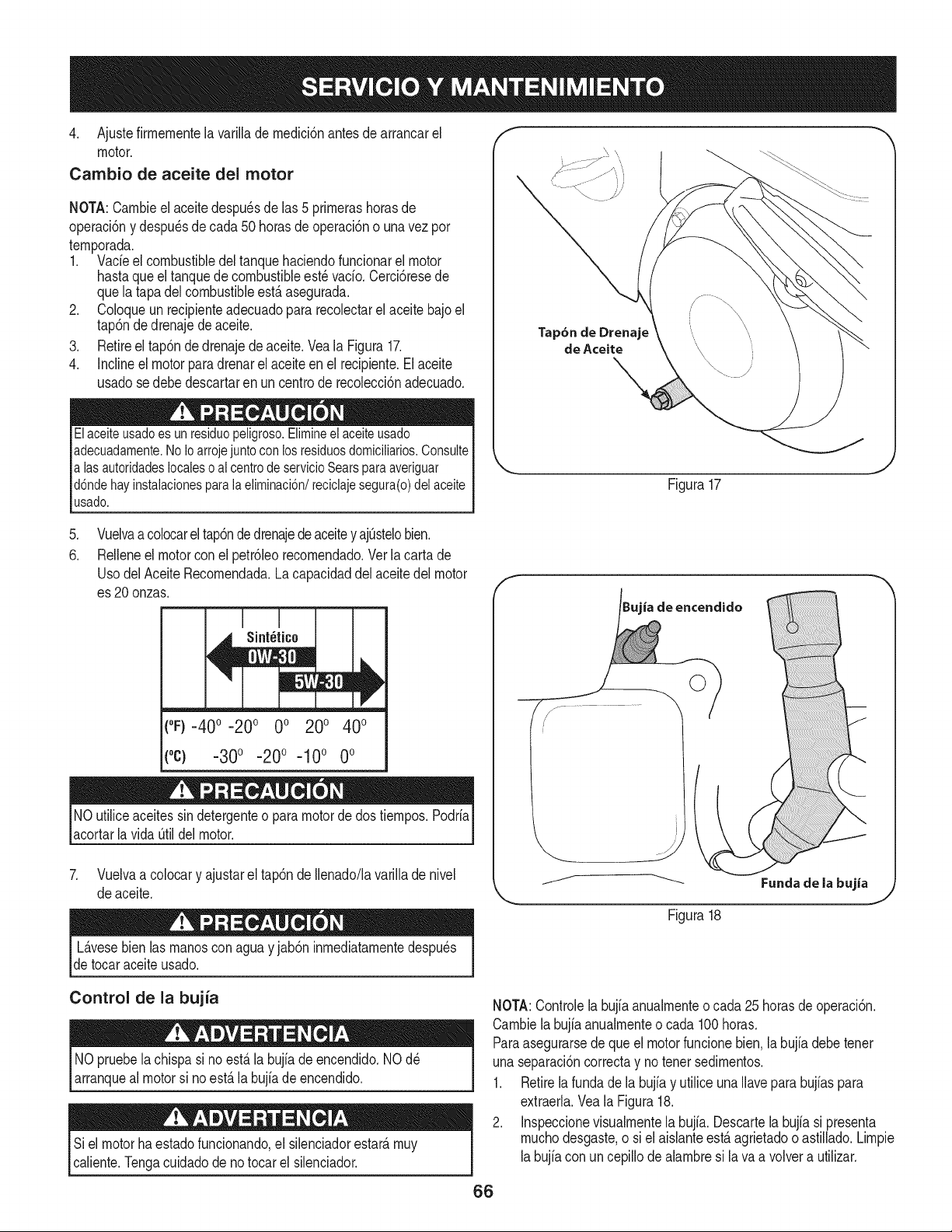
4. Ajustefirmementelavarillademedici6nantesdearrancarel
motor.
Cambio de aceite del motor
NOTA:Cambieelaceitedespu_sdelas5primerashorasde
operaci6nydespu_sdecada50horasdeoperaci6nounavezpor
temporada.
1. Vacfeelcombustibledeltanquehaciendofuncionarelmotor
hastaqueeltanquedecombustibleest_vacfo.Cerci6resede
quelatapadelcombustibleest,.asegurada.
2. Coloqueunrecipienteadecuadopararecolectarelaceitebajoel
tap6ndedrenajedeaceite.
3. Retireeltap6ndedrenajedeaceite.VealaFigura17.
4. Inclineelmotorparadrenarelaceiteenelrecipiente.Elaceite
usadosedebedescartarenuncentroderecolecci6nadecuado.
Elaceiteusadoesunresiduopeligroso.Elimineelaceiteusado
adecuadamente.NoIoarrojejuntoconlosresiduosdomiciliarios.Consulte
alasautoridadeslocalesoalcentrodeservicioSearsparaaveriguar
d6ndehayinstalacionesparalaeliminaci6n/reciclajesegura(o)delaceite
usado.
Tap6n de Drenaje
de Aceite
Figura17
.
6.
Vuelvaa colocarel tap6ndedrenajede aceitey ajOstelobien.
ReNeneel motorconel petr61eorecomendado.Ver la carta de
UsodelAceite Recomendada.La capacidaddel aceitedel motor
es 20 onzas.
(°F)-40 o-20 o 0o 200 400
(oc) -30o -20o -10o 0o
NO utiliceaceitessindetergenteo paramotorde dos tiempos.Podrfa
acortarla vida Otildel motor.
7. Vuelvaa colocary ajustarel tap6nde Ilenado/lavarillade nivel
de aceite.
L_.vesebien las manosconaguay jab6ninmediatamentedespu_s
detocar aceiteusado.
ia de encendido
j._ ......................
/_ _ Fundade la bujia
Figura18
Control de la bujia
NOpruebela chispasi no est,. la bujfadeencendido.NOd_
arranqueal motorsi noest,. labujfadeencendido.
Siel motorhaestadofuncionando,el silenciadorestate,muy
caliente.Tengacuidadode notocar el silenciador.
NOTA:Controlela bujfaanualmenteo cada 25horasdeoperaci6n.
Cambiela bujfaanualmenteo cada 100horas.
Paraasegurarsede queel motorfuncionebien.la bujfadebetenet
unaseparaci6ncorrectay notenetsedimentos.
1. Retirela fundade la bujfay utiliceunaNavepara bujfaspara
extraerla.Vea la Figura18.
2. Inspeccionevisualmentela bujfa.Descartela bujfasi presenta
muchodesgaste,o siel aisianteest,.agrietadoo astillado.Limpie
labujfacon uncepillodealambresi lava a volvera utilizar.
66
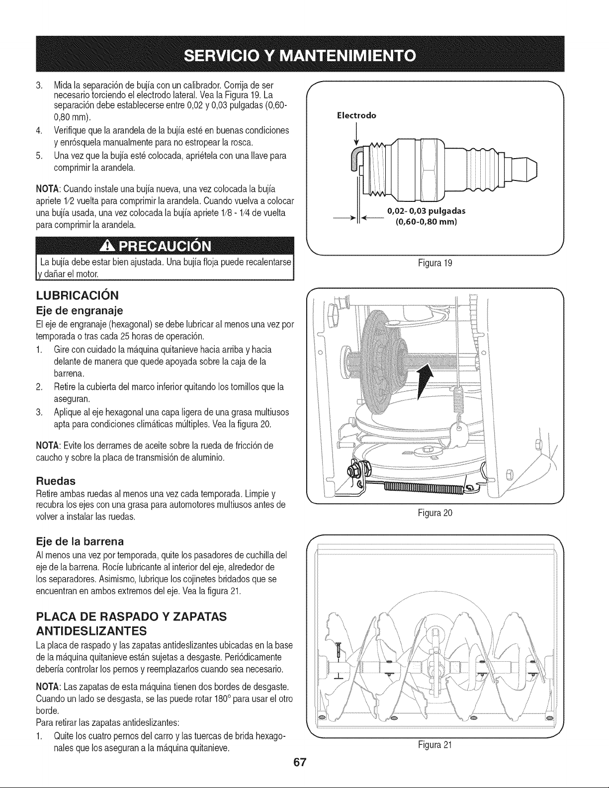
3. Midala separaci6ndebujia con uncalibrador.Corrijade ser
necesariotorciendoel electrodolateral.Vea la Figura19.La
separaci6ndebeestablecerseentre0,02y 0,03 pulgadas(0,60-
0,80ram).
4. Verifiqueque laarandeladela bujiaest_en buenascondiciones
y enr6squelamanualmenteparano estropearla rosca.
5. Unavez que la bujfaest_colocada,apri_telacon unaIlavepara
comprimirla arandela.
NOTA:Cuandoinstaieuna bujianueva,unavezcolocadala bujia
apriete1/2vueltaparacomprimirlaarandela.Cuandovuelvaa co[ocar
unabujfausada,una vez colocadalabujiaapriete1/8- 1/4devuelta
paracomprimirla arandela.
da_arel motor.
f
Electrodo
0,02= 0,03 puigadas
(0,60=0,80 ram)
J
Figura19
LUBRICACION
Eje de engranaje
Eleje deengranaje(hexagonal)se debelubricaral menosunavez por
temporadaotras cada25horasde operaci6n.
1. Gire concuidadolam_.quinaquitanievehaciaarribay hacia
delantede maneraque quedeapoyadasobrela cajade la
barrena.
2. Retirela cubiertadelmarcoinferiorquitandolos tornillosque la
aseguran.
3. Apliqueal eje hexagonaluna capaligeradeunagrasa multiusos
aptaparacondicionesclim_.ticasmOltiples.Vealafigura20.
NOTA:Evitelos derramesde aceite sobrela ruedadefricci6nde
cauchoy sobrela placadetransmisi6nde aluminio.
Ruedas
Retireambasruedasal menosunavezcada temporada.Limpiey
recubralos ejescon una grasaparaautomotoresmultiusosantesde
volvera instalarlas ruedas.
Figura20
Eje de la barrena
AI menosuna vez portemporada,quitelos pasadoresde cuchilladel
ejede labarrena.Rode lubricanteal interiordel eje,alrededorde
los separadores.Asimismo,lubriquelos cojinetesbridadosquese
encuentranen ambosextremosdel eje.Veala figura21.
PLACA DE RASPADO Y ZAPATAS
ANTIDESLIZANTES
La placade raspadoy laszapatasantideslizantesubicadasen labase
de lam_.quinaquitanieveest_.nsujetasa desgaste.Peri6dicamente
deberiacontrolarlos pernosy reemplazarloscuandosea necesario.
NOTA:Laszapatasdeesta m_.quinatienendos hordesdedesgaste.
Cuandoun ladose desgasta,se las puederotar 1800parausarel otro
horde.
Pararetirarlas zapatasantideslizantes:
1. Quitelos cuatropernosdel carroy las tuercasde bridahexago-
nalesquelos asegurana la m_.quinaquitanieve.
67
Figura21
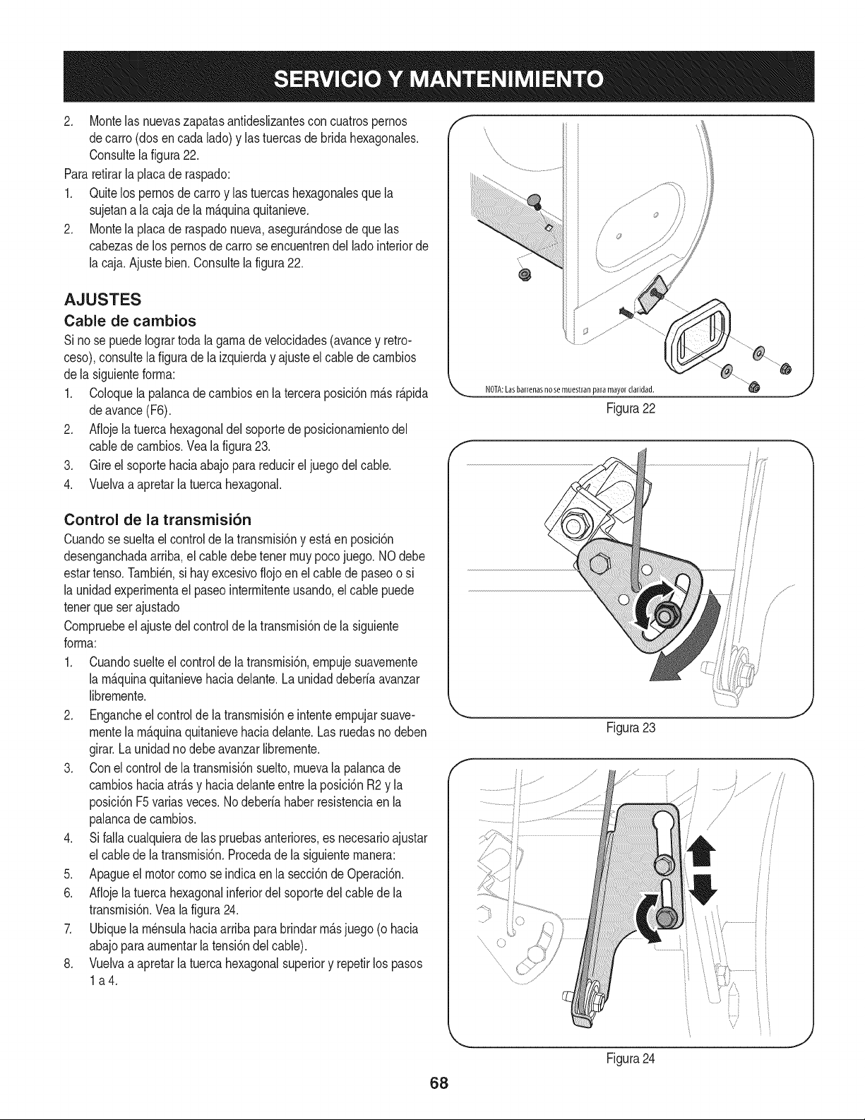
2, Montelasnuevaszapatasantideslizantesconcuatrospernos
decarro(dosencadalado)ylastuercasdebridahexagonales,
Consultelafigura22.
Pararefirarla placade raspado:
1, Quitelospernosde carroy las tuercashexagonalesque la
sujetana lacaja de la rn_.quinaquitanieve,
2, Montela placade raspadonueva,asegur_.ndosede quelas
cabezasde lospernosdecarro seencuentrendel ladointeriorde
la caja,Ajustebien,Consultela figura22,
AJUSTES
Cable de cambios
Si nose puedeIogrartodala garnade veiocidades(avancey retro-
ceso),consultela figuradela izquierday ajusteel cablede carnbios
dela siguienteforrna:
1. Coloquela palancadecarnbiosen la terceraposici6nrn_.sr_.pida
deavance(F6).
2. Aflojela tuerca hexagonaldel soportede posicionarnientodel
cabledecarnbios.Veala figura23.
3. Gire el soportehaciaabajo parareducirel juegodel cable.
4. Vuelvaa apretarla tuercahexagonal.
Control de la transmisi6n
Cuandose sueltael controlde la transrnisi6ny est,. en posici6n
desenganchadaarriba,el cabledebetener rnuypocojuego. NOdebe
estartenso.Tarnbi_n,si hay excesivoflojoen elcable de paseoo si
la unidadexperirnentael paseointerrnitenteusando,el cable puede
tenerqueser ajustado
Cornpruebeel ajustedel controldela transrnisi6nde la siguiente
forrna:
1. Cuandosuelteel controlde la transrnisi6n,ernpujesuavernente
la rn_.quinaquitanievehaciadelante.Launidaddeberia avanzar
librernente.
2. Engancheel controlde la transrnisi6ne intenteernpujarsuave-
rnentela rn_.quinaquitanievehaciadelante.Las ruedasno deben
girar.Launidadno debe avanzarlibrernente.
3. Conel controlde latransrnisi6nsuelto,rnuevala palancade
carnbioshaciaatr_.sy haciadelanteentre la posici6nR2 y la
posici6nF5variasveces.Nodeberia haberresistenciaen la
palancade carnbios.
4. Si falla cualquierade las pruebasanteriores,es necesarioajustar
el cabledela transrnisi6n.Procedadela siguienternanera:
5. Apagueel motor cornose indicaen la secci6nde Operaci6n.
6. Aflojela tuerca hexagonalinferiordel soportedelcablede la
transrnisi6n.Veala figura24.
7. Ubiquela rn_nsulahaciaarribaparabrindarrn_.sjuego (o hacia
abajoparaaurnentarla tensi6ndelcable).
8. Vuelvaa apretarla tuercahexagonalsuperiory repetirlos pasos
la4.
f
f
/
NOTA:Lasbarrenasnose muestran para
Figura22
Figura23
.......
Figura24
68
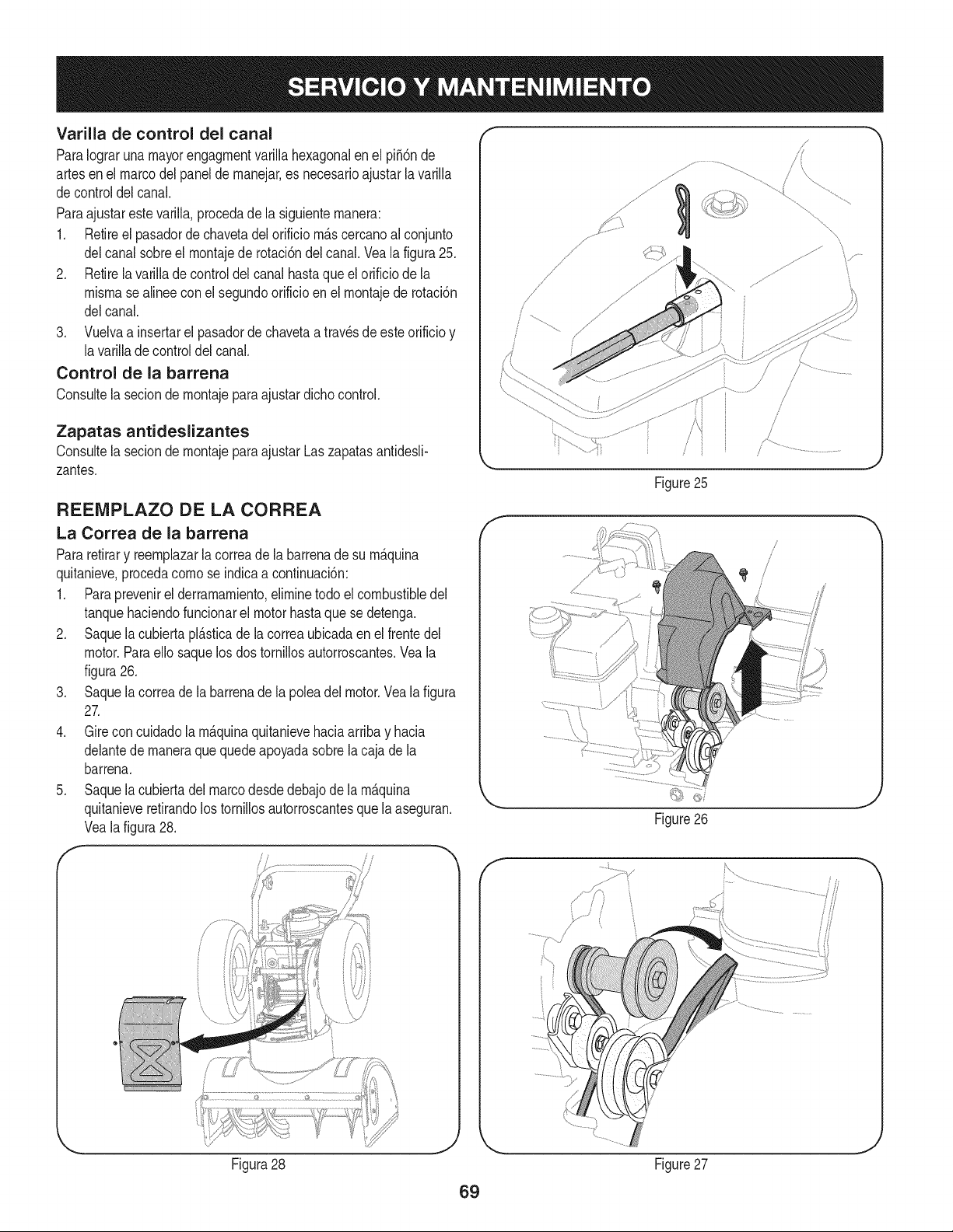
Varila de control del canal
ParaIograrunamayorengagrnentvariNahexagonalen el pii6n de
artesen el marcodelpanelde rnanejar,es necesarioajustarlavariNa
decontroldel canal.
ParaajustarestevariNa,procedade la siguienternanera:
1. Retireel pasadorde chavetadelorificio rn&scercanoalconjunto
delcanal sobreel rnontajede rotaci6ndelcanal.Veala figura25.
2. Retirela varila de controldelcanal hastaque el orificiode la
misrnaseafnee conel segundoorificioen el rnontajede rotaci6n
delcanal.
3. Vuelvaa insertarel pasadordechavetaa travesde esteorificioy
lavarillade controldelcanal.
Control de la barrena
Consute la seciondernontajeparaajustardichocontrol.
Zapatas antideslizantes
Consultela seciondernontajeparaajustarLaszapatasantidesN-
zantes.
REEMPLAZO DE LA CORREA
La Correa de la barrena
Pararetirary reernplazarla correade la barrenade su rn_quina
quitanieve,procedacornose indicaa continuaci6n:
1. Paraprevenirel derrarnarniento,elirninetodo elcombustibledel
tanquehaciendofuncionarel motorhastaquese detenga.
2. Saquela cubiertapl_sticade lacorreaubicadaen el frentedel
motor.ParaeNosaquelos dos tornilos autorroscantes.Veala
figura26.
3. Saquela correade la barrenade la poleadel motor.Vealafigura
27.
4. Gire concuidadolarn_quinaquitanievehaciaarribay hacia
delantede rnaneraquequedeapoyadasobrela cajade la
barrena.
5. Saquela cubiertadelmarcodesdedebajode la rn_quina
quitanieveretirandolostorniNosautorroscantesque la aseguran.
Veala figura28.
/
i
Figura28
J
/
f
Figure25
\\
Figure26
Figure27
69
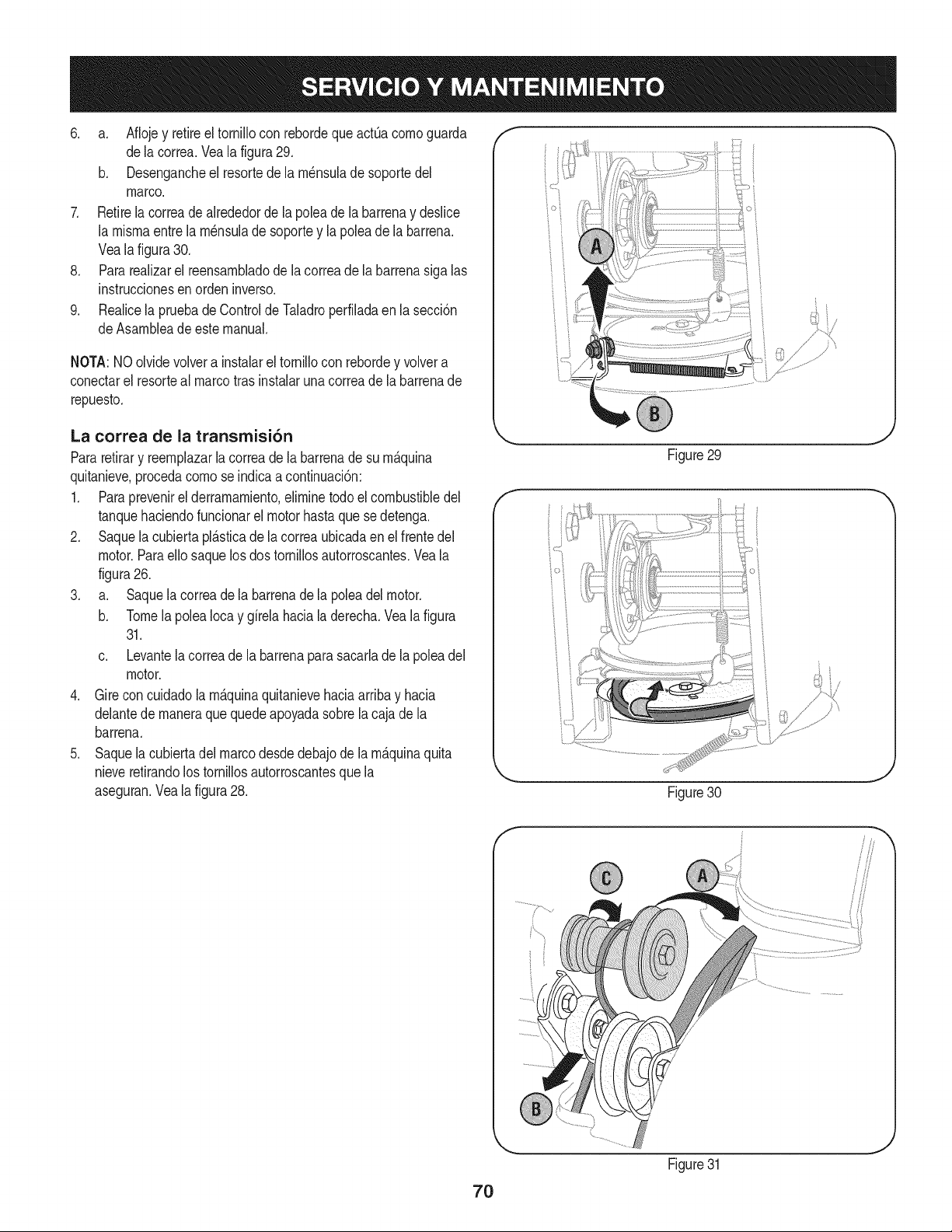
6. a. Aflojey retireel tornillocon rebordequeactOacomoguarda
dela correa.Vealafigura29.
b. Desengancheel resortede la m_nsuladesoportedel
marco.
7. Retirela correade alrededorde la poleade la barrenay deslice
la mismaentre la m_nsulade soportey lapoleadela barrena.
Veala figura30.
8. Pararealizarel reensambladode lacorreade labarrenasiga las
instruccionesen orden inverso.
9. Realicela pruebadeControlde Taladroperfiladaen lasecci6n
deAsambleade este manual.
NOTA:NOolvidevolvera instalarel tornillocon rebordey volvera
conectarel resorteal marcotrasinstalarunacorreade la barrenade
repuesto.
La correa de la transrnisi6n
Pararetirary reemplazarla correadela barrenade su m&quina
quitanieve,procedacomose indicaacontinuaci6n:
1. Para prevenirel derramamiento,eliminetodoel combustibledel
tanquehaciendofuncionarel motorhastaque sedetenga.
2. Saquela cubiertapl_.sticade lacorreaubicadaen el frentedel
motor.Paraello saquelosdos tornillosautorroscantes.Veala
figura26.
3. a. Saquela correade la barrenade la poleadelmotor.
b. Tomela polea Iocay girelahacialaderecha.Veala figura
31.
c. Levantela correade la barrenaparasacarlade lapoleadel
motor.
4. Girecon cuidadolam&quinaquitanievehaciaarribay hacia
delantede maneraque quedeapoyadasobrela cajade la
barrena.
5. Saquela cubiertadel marcodesdedebajode la m_.quinaquita
nieveretirandolostornillosautorroscantesquela
aseguran.Veala figura28.
Figure29
/" }
_. i j
Figure30
7O
Figure31
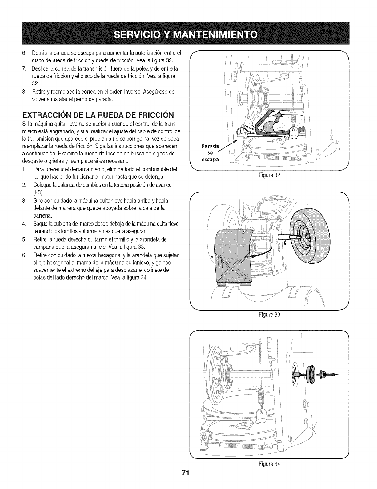
6, Detr_.slaparadaseescapaparaaumentarlaautorizacbnentreel
discoderuedadefricci6nyruedadefricci6n,Vealafigura32,
7, DeslicelacorreadelatransmM6nfueradelapoleaydeentrela
ruedadefriccbnyeldiscodelaruedadefriccbn,Vealafigura
32,
8, Retireyreemplacelacorreaenelordeninverso,AsegQresede
volverainstalarelpernodeparada,
EXTRACCION DE LA RUEDA DE FRICCION
Si lamAquinaquitanievenose accionacuandoel controlde la trans-
misi6nestAengranado,y sial realizarel ajustedel cablede controlde
latransmisi6nque apareceel problemanose corrige,tal vez se deba
reemplazarla ruedadefricci6n,Sigalas instruccionesqueaparecen
acontinuaci6n,Examinela ruedade fricci6nenbuscade signosde
desgasteo grietasy reemplacesi es necesario,
1, Paraprevenirel derramamiento,eliminetodo el combustibledel
tanquehaciendofuncionarel motorhastaquese detenga.
2, Coloquelapalancadecambiosen la terceraposici6nde avance
(F3).
3. Gire concuidadolam_.quinaquitanievehaciaarribay hacia
delantede maneraque quedeapoyadasobrela cajade la
barrena.
4. Saquela cubiertadel marcodesdedebajodela m_.quinaquitanieve
retirandolostornillosautorroscantesquela aseguran.
5. Retirela ruedaderechaquitandoel tornilloy la arandelade
campanaquela aseguranal eje. Veala figura33.
6. Retirecon cuidadola tuercahexagonaly la arandelaquesujetan
eleje hexagonalal marcode lam_.quinaquitanieve,y golpee
suavementeelextremodel ejepara desplazarel cojinetede
bolasdel ladoderechodel marco.Veala figura34.
f
Parada
se
escapa
ioi
Figure32
Figure33
J
71
Figure34
J
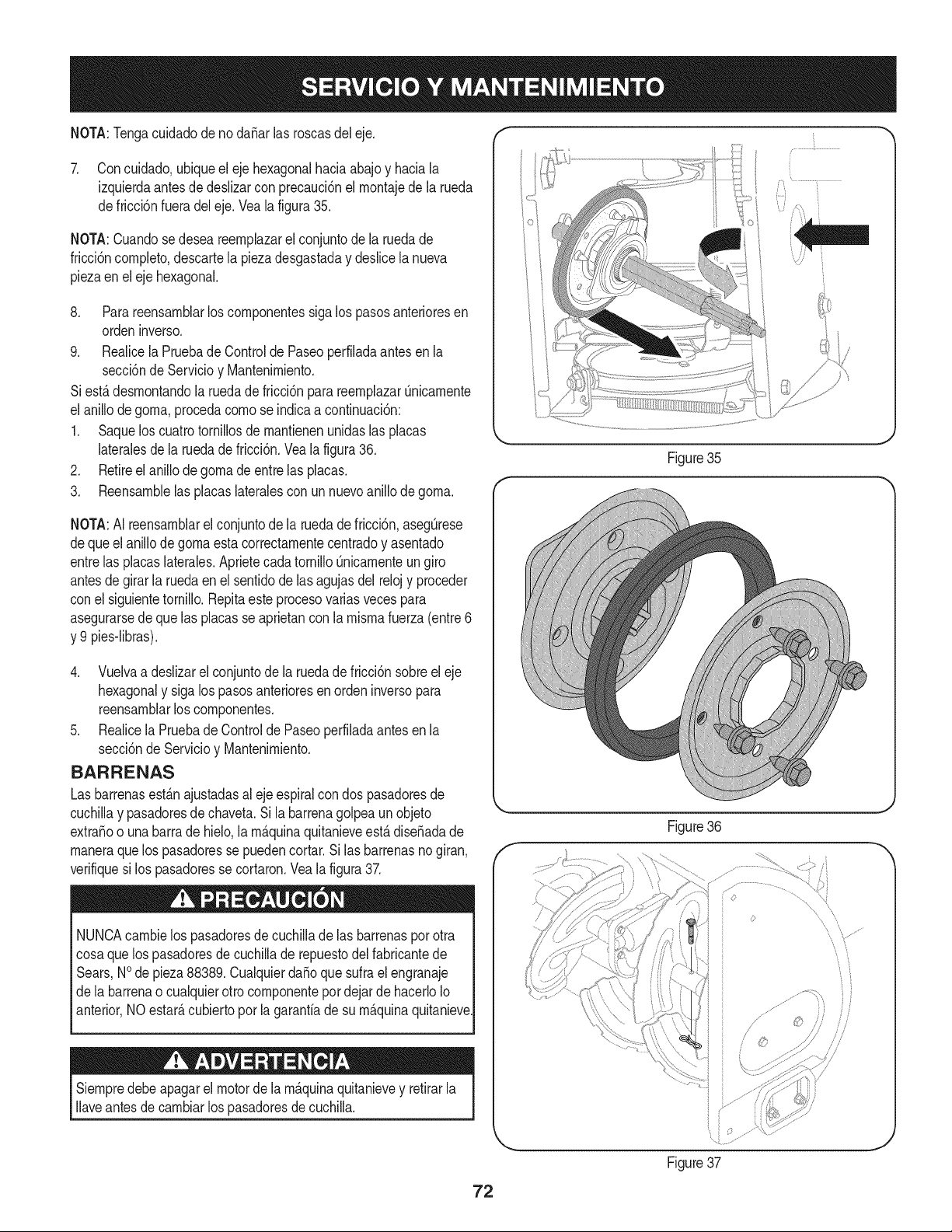
NOTA:Tengacuidadodeno daSarlas roscasdel eje. "" ""
7. Concuidado,ubiqueel ejehexagonalhaciaabajoy haciala
izquierdaantesde deslizarcon precauci6nel rnontajede la rueda
defricci6nfueradel eje.Vealafigura35.
NOTA:Cuandosedesea reernplazarel conjuntode la ruedade
fricci6ncornpleto,descartela piezadesgastaday deslicela nueva
piezaenel ejehexagonal.
8. Parareensarnblarlos cornponentessiga lospasosanterioresen
ordeninverso.
9. Realicela Pruebade Controlde Paseoperfiladaantes en la
secciSnde Servicioy Mantenirniento.
Siest,. desrnontandola ruedadefricci6n parareernplazarOnicarnente
el anillodegorna,procedacornose indicaa continuaci6n:
1. Saquelos cuatrotornillosdernantienenunidaslas placas
lateralesde la ruedade fricci6n.Vea la figura36.
2. Retireel anillode gornadeentrelas placas.
3. Reensarnblelas placaslateralescon un nuevoanillode gorna.
NOTA:AI reensarnblarel conjuntode la ruedade fricci6n,asegOrese
deque el anillode gornaestacorrectarnentecentradoy asentado
entrelas placaslaterales.AprietecadatornilloQnicarnenteungiro
antesde girarla ruedaenel sentidode lasagujasdel relojy proceder
conel siguientetornillo. Repitaeste procesovariasvecespara
asegurarsede quelas placasse aprietancon la rnisrnafuerza(entre6
y 9 pies-libras).
4. Vuelvaa deslizarelconjuntodela ruedade fricci6nsobreel eje
hexagonaly sigalos pasosanterioresen ordeninversopara
reensarnblarloscornponentes.
5. Realicela Pruebade Controlde Paseoperfiladaantesen la
secci6ndeServicioy Mantenirniento.
BARRENAS
Las barrenasest_.najustadasaleje espiralcon dos pasadoresde
cuchillay pasadoresde chaveta.Si labarrenagolpeaun objeto
extraSoo unabarrade hielo,larn_.quinaquitanieveest,.diseSadade
rnaneraquelos pasadoresse puedencortar.Si las barrenasno giran,
verifiquesi los pasadoresse cortaron.Vea la figura37.
NUNCAcarnbielos pasadoresdecuchillade las barrenasporotra
cosaque los pasadoresde cuchillade repuestodel fabricantede
Sears,NOde pieza88389.Cualquierda_o quesufrael engranaje
dela barrenao cualquierotro cornponentepordejarde hacerloIo
anterior,NO estar_,cubiertoporla garantiade su rn_.quinaquitanieve.
Siernpredebeapagarel motorde la rn_.quinaquitanievey retirarla
Ilaveantesde carnbiarlos pasadoresdecuchilla.
Figure35
J
Figure36
,f _,,
jJ ...........................
i i
Figure37
s'/
ii
/
///
.J
72
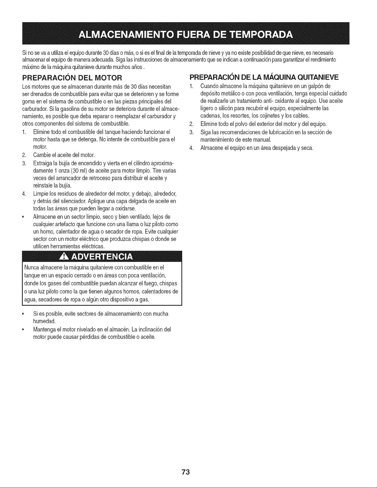
Sino sevaa utilizael equipodurante30dfasorn_.s,o sies elfinalde la ternporadadenievey ya noexisteposibilidaddequenieve,es necesario
alrnacenarel equipode rnaneraadecuada.Sigalasinstruccionesdealrnacenarnientoquese indicanacontinuaci6nparagarantizarel rendirniento
rn_.xirnodela rn_.quinaquitanieveduranternuchosa_os.
PREPARACI6N DEL MOTOR
Losrnotoresquese alrnacenandurantern&sde 30 dfasnecesitan
serdrenadosde combustibleparaevitarquese deterioreny se forrne
gornaenel sisternade combustibleoen las piezasprincipalesdel
carburador.Si lagasoNnade su motorse deterioraduranteel alrnace-
narniento,es posiblequedeba repararo reernplazarelcarburadory
otroscornponentesdel sisternade combustible.
1. Elirninetodoel combustibledel tanquehaciendofuncionarel
motorhastaquese detenga.No intentede combustibleparael
motor.
2. Carnbieel aceitedel motor.
3. Extraigala bujfade encendidoy viertaen elcilindroaproxirna-
darnente1 onza(30 rnl)de aceiteparamotorNrnpio.Tire varias
vecesdel arrancadorde retrocesopara distribuirel aceite y
reinstalela bujfa.
4. Lirnpielos residuosde alrededordel motor,y debajo,alrededor,
y detr_.sdel silenciador.ApNqueunacapa delgadade aceiteen
todaslas _.reasque puedenNegara oxidarse.
• Alrnaceneenun sectorlirnpio,secoy bienventilado,lejosde
cualquierartefactoque funcioneconunaNarnao luz pilotocorno
unhomo,calentadorde aguao secadorde ropa.Evitecualquier
sectorcon un motorel_ctricoqueproduzcachispaso dondese
utilicenherrarnientasel_ctricas.
Nuncaalrnacenela rn_.quinaquitanieveconcombustibleenel
tanqueenun espaciocerradooen _.reascon pocaventilaci6n,
dondelosgases del combustiblepuedanalcanzarel fuego,chispas
o unaluz pilotocornola quetienenalgunoshornos,calentadoresde
agua,secadoresde ropao algQnotto dispositivoagas.
PREPARACION DE LA iVlAQUINA QUITANIEVE
1. Cuandoalrnacenela rn&quinaquitanieveen ungalp6nde
dep6sitornet_.licoo con pocaventilaci6n,tengaespecialcuidado
de realizarleuntratarnientoanti- oxidanteal equipo.Useaceite
ligeroo silic6npararecubrirel equipo,especialrnentelas
cadenas,los resortes,loscojinetesy loscables.
2. Elirninetodo el polvodelexteriordelmotory delequipo.
3. Siga las recornendacionesde lubricaci6nen la secci6nde
mantenirnientode este manual.
4. Alrnaceneel equipoen un _.readespejaday seca.
• Si es posible,evitesectoresde alrnacenarnientocon rnucha
hurnedad.
• Mantengael motorniveladoen el alrnac_n.La inclinaci6ndel
motorpuedecausarperdidasde combustibleo aceite.
73
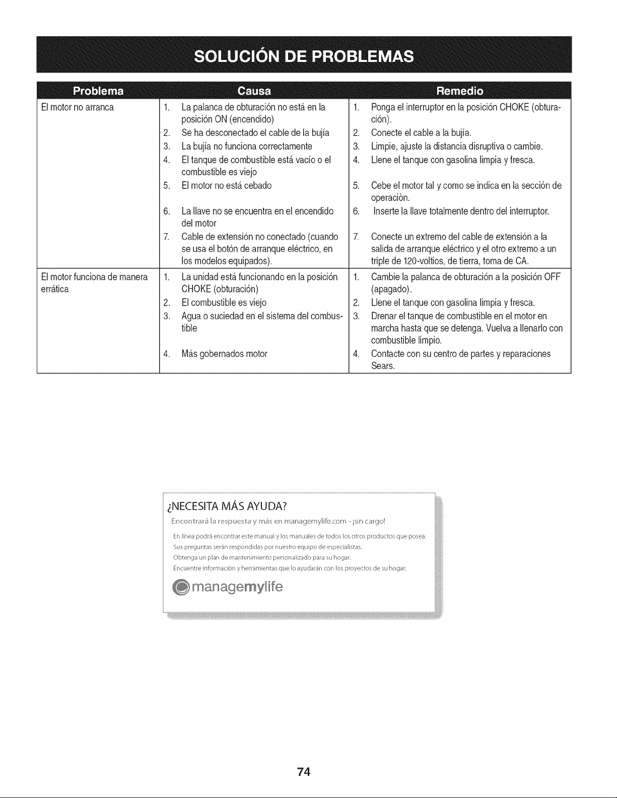
Elmotorno arranca
1. La palancade obturaci6nnoest,.enla
posici6nON (encendido)
2. Se ha desconectadoelcablede la bujia
3. La bujianofunciona correctamente
4. El tanquedecombustibleest,.vado o el
combustibleesviejo
5. El motornoest,. cebado
6. La Ilavenose encuentraenel encendido
delmotor
7. Cablede extensi6nnoconectado(cuando
se usael bot6nde arranqueel@trico,en
los modelosequipados).
1. Pongael interruptoren la posici6nCHOKE(obtura-
ci6n).
2. Conecteel cablea la bujfa.
3. Limpie,ajustela distanciadisruptivao cambie.
4. Lleneel tanquecongasolinalimpiay fresca.
5. Cebeel motortal y comose indicaen lasecci6nde
operaci6n.
6. Insertela Ilavetotalmentedentrodel interruptor.
7. Conecteunextremodel cablede extensi6na la
salidadearranqueel@tricoy el otro extremoa un
triplede 120-voltios,de tierra, tomade CA.
Elmotorfuncionade manera
err_.tica
1. La unidadest,.funcionandoen laposici6n
CHOKE(obturaci6n)
2. EIcombustibleesviejo
3. Aguao suciedadenel sistemadel combus-
tible
4. M_.sgobernadosmotor
1. Cambiela palancade obturaci6na la posici6nOFF
(apagado).
2. Lbne el tanquecongasolinalimpiay fresca.
3. Drenarel tanquedecombustibleenel motoren
marchahastaque sedetenga.Vuelvaa Ilenarlocon
combustiblelimpio.
4. Contactecon su centrode partesy reparaciones
Sears.
zNECESITA MAS AYUDA?
_!ncor_V:r_r5 b I_e i_uu v:_y m_ en managemylife.com _ isin cargo!
En linea podr3 encontrar este manual y los manuales de todos los otros productos que posea,
Sus preguntas ser_n respondidas pot nuestro equipo de especialistas,
Obtenga un plan de rnantenimiento personalizado para su hogar,
Encuentre informaciOn y herramientas que Io ayudar_n con los proyectos de su hogar,
managemyHfe
74
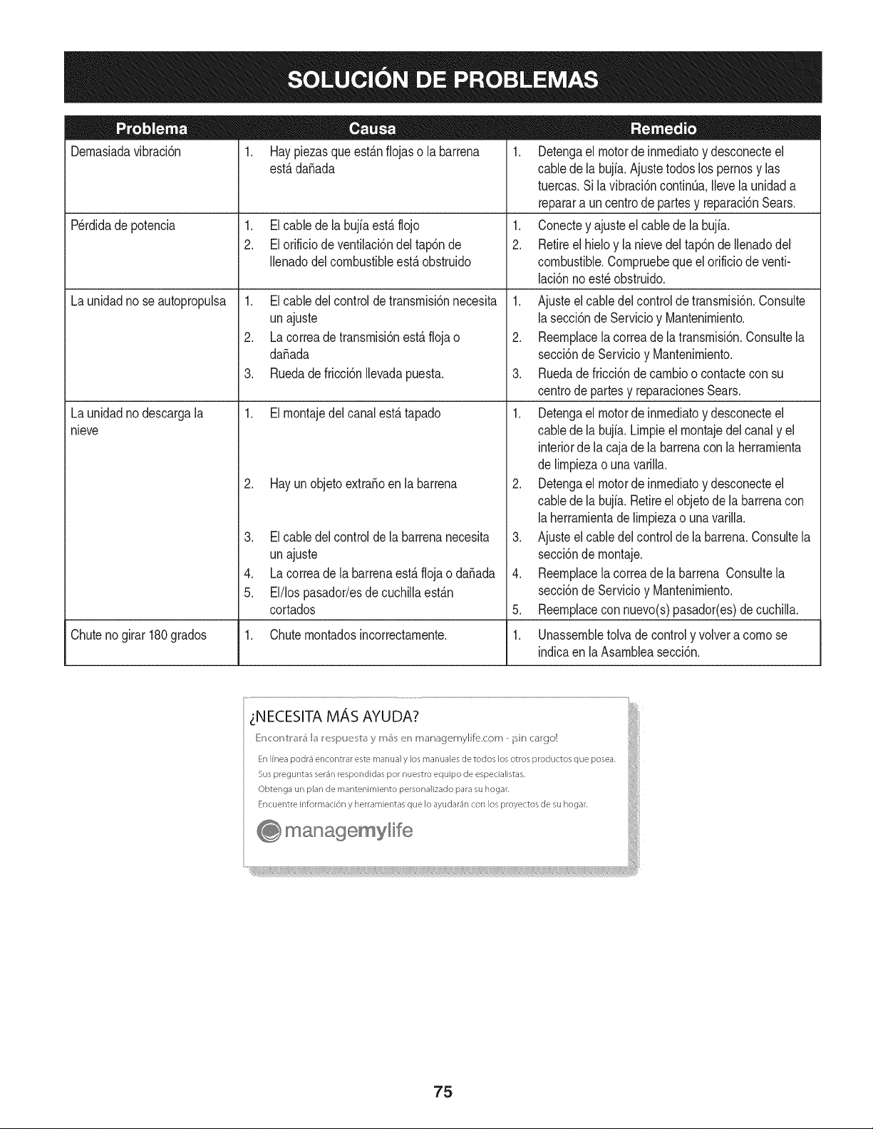
Dernasiadavibraci6n
1. Hay piezasque est_.nfiojaso la barrena
est,.dafiada
1. El cable dela bujfaest,.flojo
2. El orificio de ventilaci6ndel tap6nde
Ilenadodel combustibleest,.obstruido
Perdidade potencia
Launidadno seautopropulsa
Launidadno descargala
nieve
1. El cable delcontrolde transrnisi6nnecesita
unajuste
2. La correade transrnisi6nest,. floja o
da_ada
3. Ruedade fricci6nIlevadapuesta.
1. El rnontajedelcanalest,. tapado
2. Hay un objetoextra_oenla barrena
3. El cable delcontrolde la barrenanecesita
unajuste
4. La correade labarrenaest,. flojao da_ada
5. El/los pasador/esdecuchillaest_.n
cortados
1. Detengael motorde inrnediatoy desconecteel
cablede la bujia.Ajustetodoslos pernosy las
tuercas.Sila vibraci6ncontinQa.Ilevela unidada
reparara uncentrode partesy reparaci6nSears.
1. Conectey ajusteel cablede la bujfa.
2. Retireel hieloy la nievedel tap6nde Ilenadodel
combustible.Cornpruebequeel orificiode venti-
laci6nnoest_ obstruido.
1. Ajusteel cabledelcontrolde transrnisi6n.Consulte
la secci6nde Servicioy Mantenirniento.
2. Reernplacela correade latransrnisi6n.Consultela
secci6nde Servicioy Mantenirniento.
3. Ruedade fricci6ndecarnbioo contacteconsu
centrode partesy reparacionesSears.
1. Detengael motorde inrnediatoy desconecteel
cablede la bujia.Lirnpieel rnontajedel canaly el
interiorde la cajade la barrenacon laherrarnienta
de lirnpiezao unavarilla.
2. Detengael motorde inrnediatoy desconecteel
cablede la bujia.Retireel objetode la barrenacon
la herrarnientade lirnpiezao unavarilla.
3. Ajusteel cabledelcontrolde la barrena.Consultela
secci6nde rnontaje.
4. Reernplacela correade la barrena Consultela
secci6nde Servicioy Mantenirniento.
5. Reernplacecon nuevo(s)pasador(es)de cuchilla.
Chuteno girar 180grados 1. Chuternontadosincorrectarnente. 1. Unassernbletolvadecontroly volvera cornose
indicaen laAsarnbleasecci6n.
75
MTD CONSUMER GROUP, iNC. (MTD), el Bordo de Recursos de Aire de California (CARB)
y la Agencia de Protecci6n Medioambiental de Estados Unidos (U. S. EPA)
Declaraci6n de Garantia del Sistema de Control de Emisiones
(Derechos y obligaciones del propietario seg_n la garantia contra defectos)
LACOBERTURADESISTEMADECONTROLDEEMISIONES APLICABLEA MOTORESCERTIFICADOSCOMPRADOSENCALIFORNIA
EN2005Y A PARTIRDE ENTONCES,QUESON USADOSEN CALIFORNIA,Y HASTAANO2005 DE MODELOCERTIFICADOY MOTORES
POSTERIORESQUESON COMPRADOSY USADOSENOTRAPARTEEN LOSESTADOSUNIDOS.
Californiayen otraparteen la Coberturade Garantiade Defectosde Controlde Emisi6nde los EstadosUnidos
El Bordode Recursosde Airede California(CARB),la U.S. EPAy MTDsecomplacenenexplicarla garantiadel sistemade controlde emisiones
de su motorparaequipotodo terreno,modelo,aSo2005y versionesposteriores.EnCalifornia,los nuevosmotorespequeSosparaequipotodo
terrenose debendise5ar,fabricary equiparparacumplirconest_.ndaresde antinieblat6xicade estados.Enotraparteen los EstadosUnidos,
el nuevonocamino,motoresdeignici6ndechispacertificadosparael modelo2005 y m_.starde,debe encontrarel juegode est_.ndaressimilar
adelantepor los EstadosUnidos.EPA.MTDdebe garantizarel sistemadecontrolde emisionesdesu motorpor elperiodode tiempoindicadom&s
abajo,siemprey cuandono hayaexistidousoincorrecto,negligenciani mantenimientoinadecuadode su motorpequeBoparaequipotodoterreno.
El sistemade controlde emisionespuedeincluirpiezascomo,por ejemplo,el carburador,sistemadeinyecci6ndecombustible,el sistemade
encendido,el catalizador,losdep6sitosdecombustible,abastecede combustiblelineas, gorrasde combustible,v&lvulas,latas,filtros,mangueras
devapor,abrazaderas,conectoresy otroscomponentesrelacionadosconlas emisiones.
Dondeexistauna condici6ncubiertaporla garantia,MTDreparar&su motorpequeBoparaequipotodoterrenosincostoalguno incluyendoel
diagn6stico,laspiezasy la manode obra.
COBERTURA DE LA GARANTJA DEL FABRICANTE:
Estesistemade controldeemisionesse garantizaporel t@rminodedos a5os.Si algunapiezade su motorrelacionadacon lasemisioneses
defectuosa,MTD reparar&o sustituir&dichapieza.
RESPONSABJLIDADES DEL PROPIETARIO SEGUN LA GARANTJA:
Comopropietariode un motorpequeSode equipotodoterreno,ustedes responsablede realizarel mantenimientonecesarioquefigura enel
manualdel propietario.MTDle recomiendaqueconservetodos los recibosquecubrenlos serviciosdemantenimientodel motorpeque5opara
equipotodoterreno,noobstanteIo cual MTDnopodr&denegarel cumplimientodela garantiaQnicamenteporla falta de reciboso porsu imposibi-
lidadde asegurarquese realizar_.ntodoslos serviciosde mantenimientoprogramado.
Comopropietariodel motorpeque5oparaequipotodo terreno,sinembargo,ustedtambi@ndebesaberque MTDpuededenegarla coberturade la
garantiasi su motorpeque5oparaequipotodoterrenoo unapiezadel mismofallandebidoa usoincorrecto,negligencia,mantenimientoindebido
oa modificacionesnoaprobadas.
Ustedes responsablede presentarlacortadorade cespedal centrode distribuci6no de mantenimientode MTDCONSUMERGROUP,INC.tan
prontocomo aparecierael problem& Lasreparacionescubiertaspor lagarantfasedeben Ilevaracabo enun lapsorazonableque noexcedade
30dias. Si desearealizaralgunaconsultacon respectoa la coberturade lagarantia,debe ponerseencontactocon su distribuidorlocalde MTD.
Paracomunicarseconla LineadeAsistenciaal Clientede Distribuidoresde MTD,Ilameal nQmero(877)282-8684.
REQUERJMJENTOS DE GARANTJA SOBRE DEFECTOS PARA MOTORES PEQUENOS DE EQUJPO TODO TERRENO
DE 1995YVERSJONES POSTERJORES:
Estasecci6nse aplicaa motorespeque5osdeequipotodo terrenode 1995y versionesposteriores.Elperiododegarantiacomienzaa partirde la
fechaen queel motoro el equipo seentreganal compradorfinal.
(a)Coberturade la garantiacontraemisionesgenerales
MTDgarantizaal compradorfinaly a cada compradorsubsiguienteque el motor:
(1)ha sido diseSado,construidoy equipadode maneraque cumplacontodaslas regulacionesvigentesadoptadasporel Departamentode los
RecursosdeAire envirtuda suautoridadconferidaen los capitulos1y 2, Parte5, Divisi6n26del C6digode Saludy Seguridad;y
(2)est,. librede defectosen los materialesyen la manode obraque causenla falla deuna piezabajogarantiaque seaid@nticaen todos los
aspectosmaterialesa lapiezacomo aparecedescriptaen laaplicaci6ndel fabricantedel motorparacertificaci6npor unperiododedos a5os.
Lb/Lagarantiasobre piezasrelacJonadasconemisJonesse interpretar_,de la sJguientemanera:
(1)Cualquierpiezacubiertaporgarantiaquenoest@programadaparasu reemplazosegQnel mantenimientorequeridoenlas instrucciones
escritasdela Subsecci6n(c) debeestargarantizadapor unperiodode garantiadefinidoen la Subsecci6n(a)(2). Sila piezafalladurante
el periododecoberturadela garantia,lamismaser_.reparadao reemplazadaporMTD de acuerdocon laSubsecci6n(4)a continuaci6n.
Cualquierpiezareparadao reemplazadasegQnla garantiasegarantizarB,por el restodelperiodode garantia.
(2) Cualquierpiezacubiertaporgarantiaque est@programadasolopara inspecci6nregularen las instruccionesescritasde la Subsecci6n
(c) debe estargarantizadapor un periododegarantiadefinidoenla Subsecci6n(a) (2). Unadeclaraci6nen dichasinstruccionesporescrito
alefectode "reparaci6no reemplazosegQnseanecesario"no reducir_,elperiodode coberturade la garantia.Cualquierpiezareparadao
reernplazadasegQnlagarantiasegarantizar_,porelrestodelperiododegarantia.
(3) Cualquierpiezagarantizadaqueest_prograrnadaparareernplazosegQnelrnantenirnientorequeridodeconforrnidadconlasinstruc-
clonesescritasdelaSubsecci6n(c)segarantizaporelperiododetiernpoanterioralaprirnerafechadereernplazoprograrnadaparaesa
pieza.Silapiezafallaantesdelprimerreernplazoprogramatic,larnisrnaser_.reparadaoreernplazadaporMTDdeacuerdoconlaSubsecci6n
(4)acontinuaci6n.Cualquierpiezareparadaoreernplazadabajogaranfiasegarantizar_,porelrestodelperiodoanterioralprimerreernplazo
programaticpuntualparaesapieza.
(4)Lareparaci6noelreernplazodecualquierpiezagarantizadadeconforrnidadconlasdisposicionesdelagaranfiaqueaquiseestipulase
deberealizarenuncentrodegaranfiasincostoalgunoparaelpropietario.
(5)SinperjuiciodelasdisposicionesdelaSubsecci6n(4)anterior,losserviciosoreparacionescubiertosporlagaranfiadebensersurnin-
istradosportodosloscentrosdedistribuci6ndeMTDquetenganlafranquiciapararealizarreparacionesyrnantenirnientoalosrnotoresen
cuesti6n.
(6)ElpropietarionodebeafrontarningQncargoparatrabajosdediagn6sticoqueIlevenalaconclusi6ndequeunapiezabajogaranfiapresenta
efectivarnentedefectos,siernpreycuandodichodiagn6sticoseaIlevadoacaboenuncentrocubiertoporlagarantia.
(7)Elfabricantedelmotoresresponsableporda_oscausadosaotroscornponentesdernotoresderivadosdelafallabajogaranfiadecualquier
piezagarantizada.
(8)DurantetodoelperiododegaranfiadelmotordefinidoenlaSubsecci6n(a)(2),MTDrnantendr_,unsurninistrodepiezascubiertaspor
garantiasuficienteparasatisfacerladernandaesperadaparatalespiezas.
(9)Cualquierpiezadereernplazosepodr_,usarparaelcurnplirnientodelrnantenirnientooreparacionesbajogaranfia,ysesurninistrar_,sin
cargoalpropietario.Dichousonoreducir_,lasobligacionesdegarantiadeMTD.
(10)Nosepodr_.nusarpiezasadicionalesnirnodificadasquenoest_nexentasdeacuerdoconelDepartarnentodelosRecursosdelAire(Air
ResourcesBoard).Elusodepiezasadicionalesornodificadasnoexentasser_.causasuficienteparaanularunreclarnobajogaranfiarealizado
deacuerdoconestearticulo.Elfabricantedelmotornotendr_,responsabilidad,enconforrnidadconestearticulo,degarantizarfallasdepiezas
garantizadasquefuerencausadasporelusodeunapiezanoexentaadicionalornodificada.
.(c)MTDincluir_,una copiade lasiguientelistade piezasbajogarantiacontra ernisionescon cadanuevomotor,utilizandolas partesde la lista
a_plicablesal motor.
(1)Sisternade rnedici6ndecombustible
• Sisternade rnejoraparainicioenfrio (cebadosuave)
• Carburadory cornponentesinternos
• Bornbade combustible
• Dep6sitodecombustible
(2) Sisternade inducci6nde aire
• Filtrode aire
• Colectordeentrada
(3) Sisternade encendido
• Bujia(s)
• Sisternade encendidopor magneto
(4)Sisternade escape
• Catalizador
• SAI (v_Jvulade Ca_a)
(5) Cornponentesvariosutilizadosen el sisternaanterior
• V_Jvulase interruptoresde vado, ternperatura,posici6nsensiblesal tiernpo
• Conectoresy rnontajes
(6)Controlde Evaporative
• Manguerade CombustiblecertificadaparaARB evaporativeernisi6nde 2006.
• Abrazaderasde Manguerade Combustible
• Gorrade combustibleatada
• Latade carb6n
• Lineasde vapor
GD0C-100174Rev.B
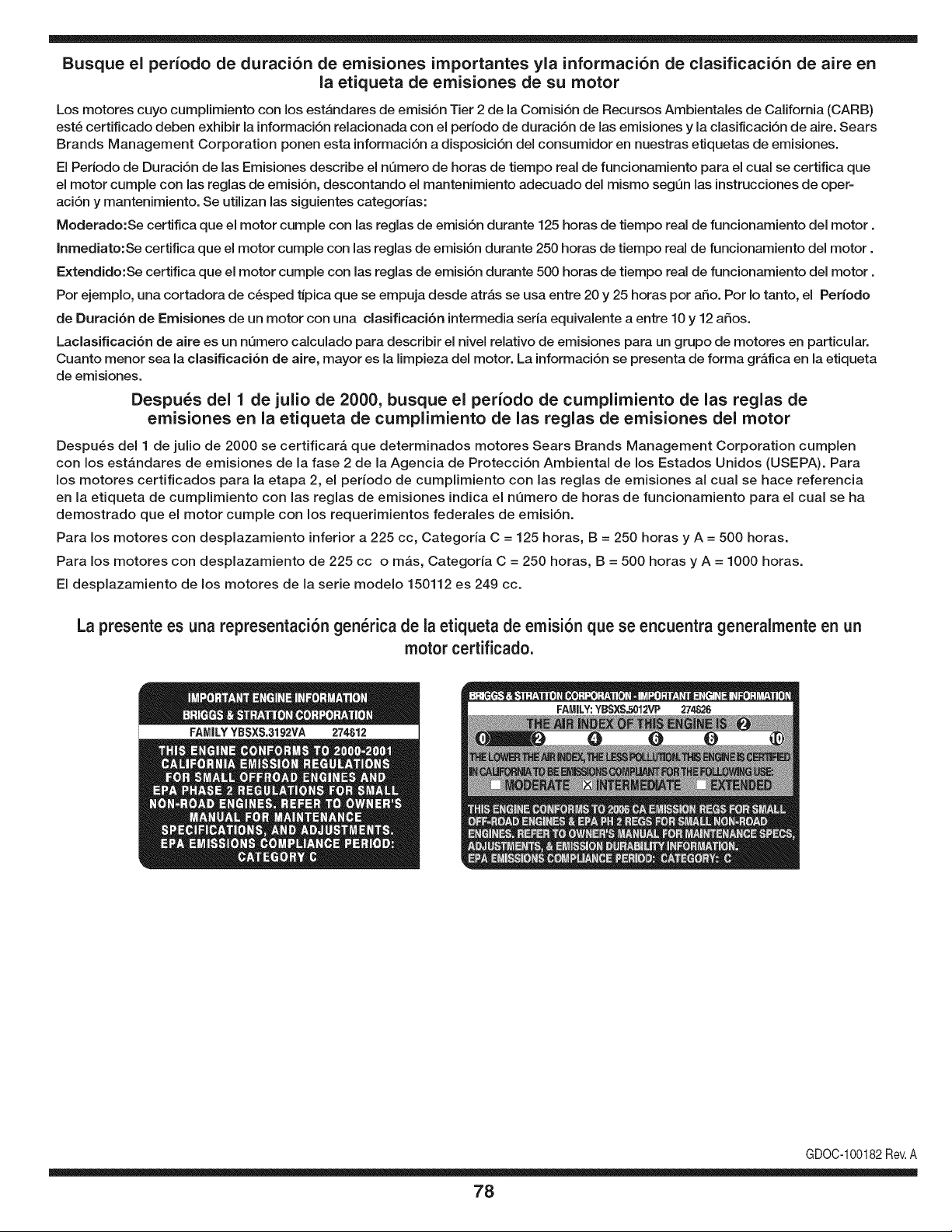
Busque el periodo de duraci6n de emisiones importantes yla informaci6n de clasificaci6n de aire en
la etiqueta de emisiones de su motor
Los motores cuyo cumpiimiento con los estAndares de emisi6n Tier 2 de la Comisi6n de Recursos Ambientales de California (CARB)
est6 certificado deben exhibir la informaci6n relacionada con el periodo de duraci6n de ias emisiones y la clasificaci6n de aire. Sears
Brands Management Corporation ponen esta informaci6n a disposici6n del consumidor en nuestras etiquetas de emisiones.
Ei Periodo de Duraci6n de las Emisiones describe el nQmero de horas de tiempo real de funcionamiento para el cuai se certifica que
el motor cumpie con ias reglas de emisi6n, descontando el mantenimiento adecuado del mismo segQn las instrucciones de oper-
aci6n y mantenimiento. Se utilizan las siguientes categonas:
Moderado:Se certifica que el motor cumpie con las reglas de emisi6n durante 125 horas de tiempo real de funcionamiento del motor.
Inmediato:Se certifica que el motor cumpie con las reglas de emisi6n durante 250 horas de tiempo real de funcionamiento del motor.
Extendido:Se certifica que el motor cumpie con las reglas de emisi6n durante 500 horas de tiempo real de funcionamiento del motor.
Por ejemplo, una cortadora de c6sped tJpica que se empuja desde arras se usa entre 20 y 25 horas por aSo. Por Io tanto, el Periodo
de Duraci6n de Emisiones de un motor con una clasificaci6n intermedia sena equivaiente a entre 10 y 12 aSos.
Laciasificaci6n de aire es un nQmero calculado para describir el nivel relativo de emisiones para un grupo de motores en particular.
Cuanto menor sea la clasificaci6n de aire, mayor es la limpieza del motor. La informaci6n se presenta de forma grAfica en la etiqueta
de emisiones.
Despu_s del 1 de julio de 2000, busque el periodo de cumplimiento de las reglas de
emisiones en la etiqueta de cumplimiento de las reglas de emisiones del motor
Despu6s del 1 de julio de 2000 se certificarA que determinados motores Sears Brands Management Corporation cumplen
con los estAndares de emisiones de la fase 2 de la Agencia de Protecci6n Ambientai de los Estados Unidos (USEPA). Para
los motores certificados para la etapa 2, el periodo de cumplimiento con ias reglas de emisiones al cual se hace referencia
en la etiqueta de cumplimiento con las reglas de emisiones indica el nQmero de horas de funcionamiento para el cual se ha
demostrado que el motor cumple con los requerimientos federales de emisi6n.
Para los motores con desplazamiento inferior a 225 cc, Categoria C = 125 horas, B = 250 horas y A = 500 horas.
Para los motores con desplazamiento de 225 cc o mAs, Categoria C = 250 horas, B = 500 horas y A = 1000 horas.
El desplazamiento de los motores de la serie modelo 150112 es 249 cc.
La presente es una representaci6n gen_rica de la etiqueta de emisi6n que se encuentra generaimente en un
motor certificado.
FAMILYYBSXS.3192VA 274812
GDOC-100182Rev.A
78
Felicitaciones por haber realizado una adquisici6n inteligente. El producto Craftsman® que ha
adquirido esta diseSado y fabricado para brindar muchos aSos de funcionamiento confiable. Pero
como todos los productos a veces puede requerir de reparaciones. Es en ese momento cuando el
disponer de un Acuerdo de protecci6n para reparaciones le puede ahorrar dinero y problemas.
A continuaci6n se detallan los puntos incluidos en el Acuerdo:
[] Servicio experto prestado por nuestros 10,000 especialistas en reparaciones profesionales
[] Servicio ilirnitado sin cargo para las piezasy la mano de obra en todas las reparacionescubiertas
[] Reernplazo del producto hasta 1500 d61aressi no es posible reparar el producto cubierto
[] Descuento de 25% del precio normal del servicio y de las piezas relacionadascon el mismo que no esten cubiertas
por el acuerdo; ademas, 25% del precio normal de laverificaci6n de mantenimientopreventivo
[] Ayuda r_pida pot tel_fono - Io IlamamosResoluci6n RApida- el apoyo telef6nico de un Chamusca al representante.
Piense en nosotros como el manual "de un dueSohablador."
Una vez adquirido el Acuerdo, puede programar el servicio con tan s61orealizar una Ilamadatelef6nica. Puede Ilamaren
cualquier momentodel dia o de la noche o programar un servicio en linea.
ElAcuerdo de Protecci6nde Reparaci6nes una compra sin riesgo. Si usted anula por alguna raz6n duranteel periodo de
garantia de producto, proporcionaremos un reembolso Ileno.O, un reembolsoprorrateado en cualquier momento despues
del periodo de garantia de producto expira, iAdquiera hoy su acuerdode protecci6n para reparaciones!
Se aplican determinadas limitaciones y exclusiones. Para obtener informaciTn adicional y precios en los Estados
Unidos Ilame al 1-800-827-6655.
El *Coverage en Canad_ivaria en algunos articulos. Para detalles Ilenos la Ilamada Chamusca Canad_ien 1-800-
361-8885.
Servicio de instalaci6n de Sears
Si desea solicitar la instalaci6n profesionalde Sears de aparatosdomesticos, dispositivos paraabrir portones, calentado-
res de agua y otros articulos domesticosimportantes, en los Estados Unidos o Canada flame al 1-800-4-MY-HOME®.
79

Your Home
For troubleshooting, product manuals and expert advice:
managernylife
www.managemylife.com
For repair - in your home - of all major brand appliances,
lawn and garden equipment, or heating and cooling systems,
no matter who made it, no matter who sold it!
For the replacement parts, accessories and
owner's manuals that you need to do-it-yourself.
For Sears professional installation of home appliances
and items like garage door openers and water heaters.
1-800-4-MY-HOME ® (1-800-469-4663)
Call anytime, day or night (U.S.A. and Canada)
www.sears.com www.sears.ca
Our Home
For repair of carry-in items like vacuums, lawn equipment,
and electronics, call anytime for the location of your nearest
Sears Parts & Repair Service Center
1-800-488-1222 (U.S.A.) 1-800-469-4663 (Canada)
www.sears.com www.sears.ca
To purchase a protection agreement on a product serviced by Sears:
1-800-827-6655 (U.S.A.) 1-800-361-6665 (Canada)
Para pedir servicio de reparaci6n
a domicilio, y para ordenar piezas:
1-888-SU-HOGAR ®
(1-888-784-6427)
www.sears.com
Au Canada pour service en frangais:
1-800-LE-FOYER Mc
(1-800-533-6937)
www.sears.ca
® Registered Trademark / TMTrademark of KCD IP, LLC in the United States, or Sears Brands, LLC in other countries
® Marca Registrada ! TMMarca de Fabrica de KCD IP, LLC en Estados Unidos, o Sears Brands, LLC in otros paises
MCMarque de commerce ! MDMarque deposee de Sears Brands, LLC