I CRRFTSMRN1
Operator's Manual
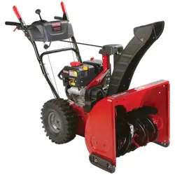
Snow Th rower
13 Horsepower
Electric Start
33-inch Dual Stage
Model 536.889251
CAUTION: Before using this product,
read this manual and follow all of its
Safety Rules and Operating Instruction=
Manual del usario
Quitanieves
de 33 pulgadas
13 caballos de fuerza (hp)
Biet&pico
Arranque el_ctrico
Modelo 536.889251
PRECAUCI6N: Antes de usar este producto,
lea este manual y siga todas las reglas de
seguridad e instrucciones de operaci6n.
Sears, Roebuck and Co., Hoffman Estates, IL 60179 U.S.A.
F-031068L www.sears.com/craftsman
NnnL*!=]I :l_o__
WARRANTY STATEMENT ...... 2
SAFETY RULES ............... 2
INTERNATIONAL SYMBOLS .... 4
ASSEMBLY ................... 6
OPERATION .................. 13
MAINTENANCE ............... 20
SERVICE AND ADJUSTMENT... 23
STORAGE .................... 32
TROUBLESHOOTING TABLE . .. 33
REPAIR PARTS ................ 39
ENGINE REPAIR PARTS ........ 59
SPANISH (ES PAIgOL) .......... 70
PARTS ORDERING/SERVICE ..
BACK COVER
LIMITED TWO-YEAR WARRANTY ON CRAFTSMAN SNOW THROWER
For two years from the date of purchase, when this Craftsman Snow thrower is maintained,
lubricated, and tuned up according to the operating and maintenance instructions in the
owner's manual, Sears will repair, free of charge, any defect in material or workmanship.
If this Craftsman Snow thrower is used for commercial or rental purposes, this warranty ap-
plies for only 90 days from the date of purchase.
This warranty does not cover the following:
Items which become worn during normal use, such as spark plugs, ddve belts end shear
pins.
Repair necessary because of operator abuse or negligence, including bent crankshafts
and the failure to maintain the equipment according to the instructions contained in the
owner's manual.
WARRANTY SERVICE IS AVAILABLE BY RETURNING THE CRAFTSMAN SNOW
THROWER TO THE NEAREST SEARS SERVICE CENTER IN THE UNITED STATES.
THIS WARRANTY APPLIES ONLY WHILE THIS PRODUCT IS IN USE IN THE UNITED
STATES.
This warranty gives you specific legal rights, and you may also have other dghts which may
vary from state to state.
Sears, Roebuck and Co., D817WA, Hoffman Estates. IL 60179
il_ll LOOK FOR THIS SYMBOL TO POINT OUT IMPORTANT SAFETY PRECAUTIONS.
IT MEANS-- ATTENTION!!! BECOME ALERT!t! YOUR SAFETY IS INVOLVED.
Engine Exhaust, some of its constituents, and
certain vehicle components contain or emit
chemicals known to the State of California to
cause cancer and birth defects or other repro-
ductive harm.
Battery posts, terminals and related accessories
contain lead and lead compounds, chemicals
known to the State of California to cause cancer
and birth defects or other reproductive harm.
WASH HANDS AFTER HANDLING.
_ WARNING: Always discon-
nect the spark plug wire
and place it where it cannot
make contact with spark plug to
prevent accidental starting during:
Preparation, Maintenance, or Stor-
age of your snow thrower.
IMPORTANT: Safety standards re-
quire operator presence controls to
minimize the risk of injury. Your snow
thrower is equipped with such controls.
Do not attempt to defeat the function of
the operator presence control under any
circumstances.
F-031068L 2
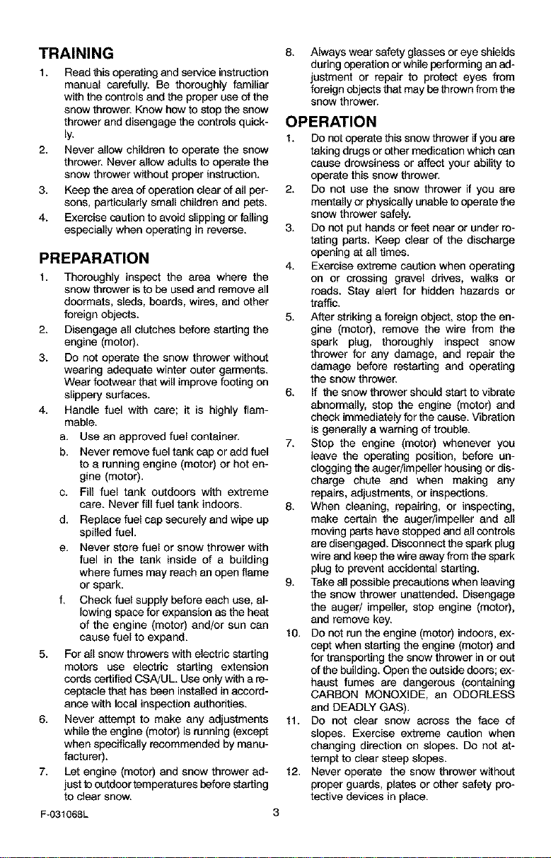
TRAINING
1. Read this operating and service instruction
manual carefully. Be thoroughly familiar
with the controls and the proper use of the
snow thrower. Know how to stop the snow
thrower and disengage the controls quick-
ly.
2. Never allow children to operate the snow
thrower. Never allow adults to operate the
snow thrower without proper instruction.
3. Keep the area of operation clear of all per-
sons, particularly small children and pets.
4. Exercise caution to avoid slipping or falling
especially when operating in reverse.
PREPARATION
1. Thoroughly inspect the area where the
snow thrower is to be used and remove all
doormats, sleds, boards, wires, and other
foreign objects.
2. Disengage all clutches before starting the
engine (motor).
3. Do not operate the snow thrower without
wearing adequate winter outer garments.
Wear footwear that will improve footing on
slippery surfaces.
4. Handle fuel with care; it is highly flam-
mable.
a. Use an approved fuel container.
b. Never remove fuel tank cap or add fuel
to a running engine (motor) or hot en-
gine (motor).
c. Fill fuel tank outdoors with extreme
care. Never fill fuel tank indoors.
d. Replace fuel cap securely and wipe up
spilled fuel.
e. Never store fuel or snow thrower with
fuel in the tank inside of a building
where fumes may reach an open flame
or spark.
f. Check fuel supply before each use, al-
lowing space for expansion as the heat
of the engine (motor) and/or sun can
cause fuel to expand.
5. For all snow throwers with electric starting
motors use electdc starting extension
cords certified CSA!UL Use only with a re-
ceptacle that has been installed in accord-
ance with local inspection anthodtles.
6. Never attempt to make any adjustments
while the engine (motor) is running (except
when specifically recommended by manu-
facturer).
7. Let engine (motor) and snow thrower ad-
just tooutdoor temperatures before starting
to clear snow.
F-031068L
Always wear safety glasses or eye shields
during operation or while performing an ad-
justment or repair to protect eyes from
foreign objects that may be thrown from the
snow thrower.
OPERATION
1. Do not operate this snow thrower it you are
taking drugs or other medication which can
cause drowsiness or affect your ability to
operate this snow thrower.
2. Do not use the snow thrower if you are
mentally or physically unable to operate the
snow thrower safely.
3. Do not put hands or feet near or under ro-
tating parts. Keep clear of the discharge
opening at all times.
4. Exercise extreme caution when operating
on or crossing gravel drives, walks or
roads. Stay alert for hidden hazards or
traffic.
5. After striking a foreign object, stop the en-
gine (motor), remove the wire from the
spark plug, thoroughly inspect snow
thrower for any damage, and repair the
damage before restarting and operating
the snow thrower.
6. If the snow thrower should start to vibrate
abnormally, stop the engine (motor) and
check immediately for the cause. Vibration
is generally e warning of trouble.
7. Stop the engine (motor) whenever you
leave the operating position, before un-
clogging the anger/impeller housing or dis-
charge chute and when making any
repairs, adjustments, or inspections.
8. When cleaning, repairing, or inspecting,
make certain the auger/impeller and all
moving parts have stopped and all controls
are disengaged. Disconnect the spark plug
wire end keep the wire away from the spark
plug to prevent accidental starting.
9. Take all possible precautions when leaving
the snow thrower unattended. Disengage
the auger/ impeller, stop engine (motor),
and remove key.
10. Do not run the engine (motor) indoors, ex-
cept when starting the engine (motor) and
for transporting the snow thrower in or out
of the building. Open the outside doors; ex-
haust fumes are dangerous (containing
CARBON MONOXIDE, an ODORLESS
and DEADLY GAS).
11. Do not clear snow across the face of
slopes. Exercise extreme caution when
changing direction on slopes. Do not at-
tempt to clear steep slopes.
12. Never operate the snow thrower without
proper guards, plates or other safety pro-
teotive devices in place.
13.Neveroperatethesnowthrowernearen-
closures,automobiles,windowwells,drop-
offs,andthelikewithoutproberadjustment
ofthesnowdischargeangle.Keepchildren
andpetsaway.
14.Donotoverloadthesnowthrowercapacity
byattemptingtoclearsnowattoofasta
rate.
15.Neveroperatethesnowthrowerathigh
transportspeedsonslipperysurfaces.
Lookbehindandusecarewhenbacking
up.
16.Neverdirectdischargeatbystandersor
allowanyoneinfrontofthesnowthrower.
17.Disengagepowertothecollecfer/impeller
whensnowthroweristransportedornotin
use.
18.Useonlyattachmentsandaccessedesap-
provedbythemanufacturerofthesnow
thrower(suchastirechains,electricstart
kits,ect.).
19.Neveroperatethesnowthrowerwithout
goodvisibilityorlight.Alwaysbesureof
yourfootingandkeepafirmholdonthe
handles.Walk;neverrun.
20.Donotover-reech.Keepproperfooting
andbalanceatalltimes.
21.Donotattempttousesnowthrowerona
roof.
MAINTENANCE AND STORAGE
1. Check shear bolts and other bolts at fre-
quent intervals for proper tightness to be
sure the snow thrower is in safe working
condition.
2. Never store the snow thrower with fuel in
the tank inside a building where ignition
sources are present such as hot water and
space heaters, clothes dryers, and the like.
Allow the engine (motor) to cool before
storing in any enclosure.
3. Always refer to operator's guide instruc-
tions for important details if the snow
thrower is to be stored for an extended
period.
4. Maintain or replace safety end instruction
labels, as necessary.
5. Run the snow thrower a few minutes after
throwing snow to prevent freeze-up of the
auger/impeller.
4_k WARNING: This snow thrower isfor use on sidewalks, driveways
and other ground level surfaces.
Caution should be exercised while using on
steep sloping surfaces. DO NOT USE
SNOW THROWER ON SURFACES ABOVE
GROUND LEVEL such as roofs of resi-
dences, garages, porches or other such
structures or buildings.
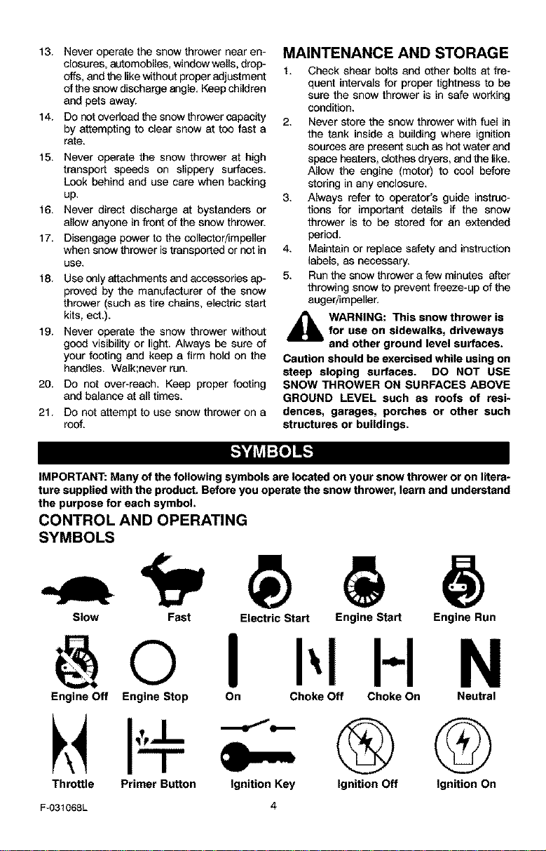
IMPORTANT: Many of the following symbols are located on your snow thrower or on litera-
ture supplied with the product. Before you operate the snow thrower, learn and understand
the purpose for each symbol.
CONTROL AND OPERATING
SYMBOLS
Slow Fast
Engine Off Engine Stop
Throttle Primer Button
Electric Start Engine Start Engine Run
I I-I N
On Choke Off Choke On Neutral
Ignition Key Ignition Off Ignition On
F-031068L
4
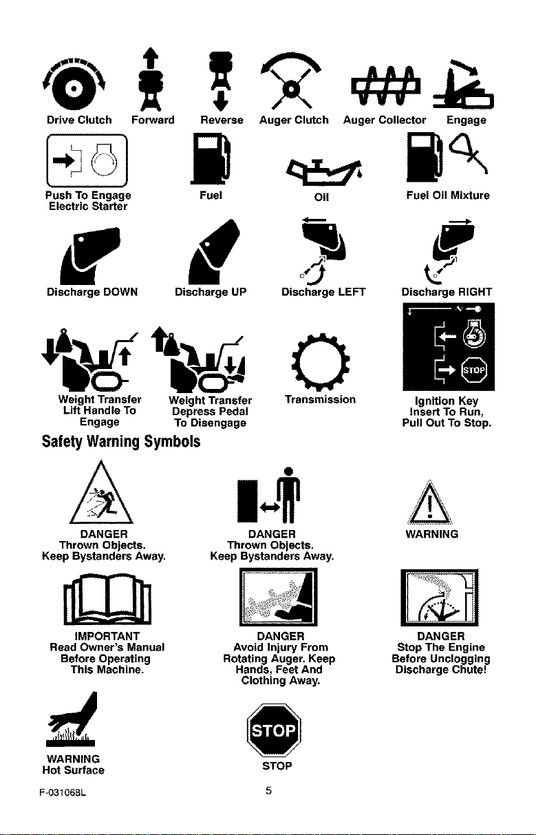
Drive Clutch Forward
Push To Engage
Electric Starter
Reverse Auger Clutch Auger Collector Engage
i
Fuel Oil Fuel Oil Mixture
Discharge DOWN Discharge UP Discharge LEFT Discharge RIGHT
m
Weight Transfer Weight Transfer Transmission Ignition Key
Lift Handle To Depress Pedal Insert To Run,
Engage To Disengage Pull Out To Stop.
Safety Warning Symbols
DANGER
Thrown Objects.
Keep Bystanders Away.
IMPORTANT
Read Owner's Manual
Before Operating
This Machine.
O
DANGER WARNING
Thrown Objects.
Keep Bystanders Away.
DANGER
Avoid Injury From
Rotating Auger. Keep
Hands, Feet And
Clothing Away.
DANGER
Stop The Engine
Before Unclogging
Discharge Chute!
WARNING
Hot Surface
STOP
F-O31068L 5
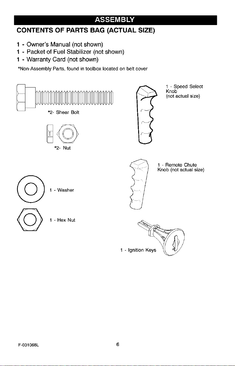
CONTENTS OF PARTS BAG (ACTUAL SIZE)
1 - Owner's Manual (not shown)
1 - Packet of Fuel Stabilizer (not shown)
1 - Warranty Card (not shown)
*Non-Assembly Parts,foundintoolboxlocatedonbeltcover
1 - Speed Select
_ Knob
(not actual size)
1 - Remote Chute
Knob (not actual size)
1 - Washer
©
1 - Hex Nut
1 - Ignit_
F-O31068L 6
,_ WARNING: Always wear
safety glasses or eye shields
while assembling snow
thrower.
TOOLS REQUIRED FOR
ASSEMBLY
1 - Knife to cut carton
2 - 1/2 inch wrenches
(or adjustable wrenches)
2 - 9/16 inch wrenches
(or adjustable wrenches)
2 - 3/4 inch wrenches
(or adjustable wrenches)
1 - Pliers (to spread cotter pin)
1 - Screwdriver
1 - Measuring tape or ruler
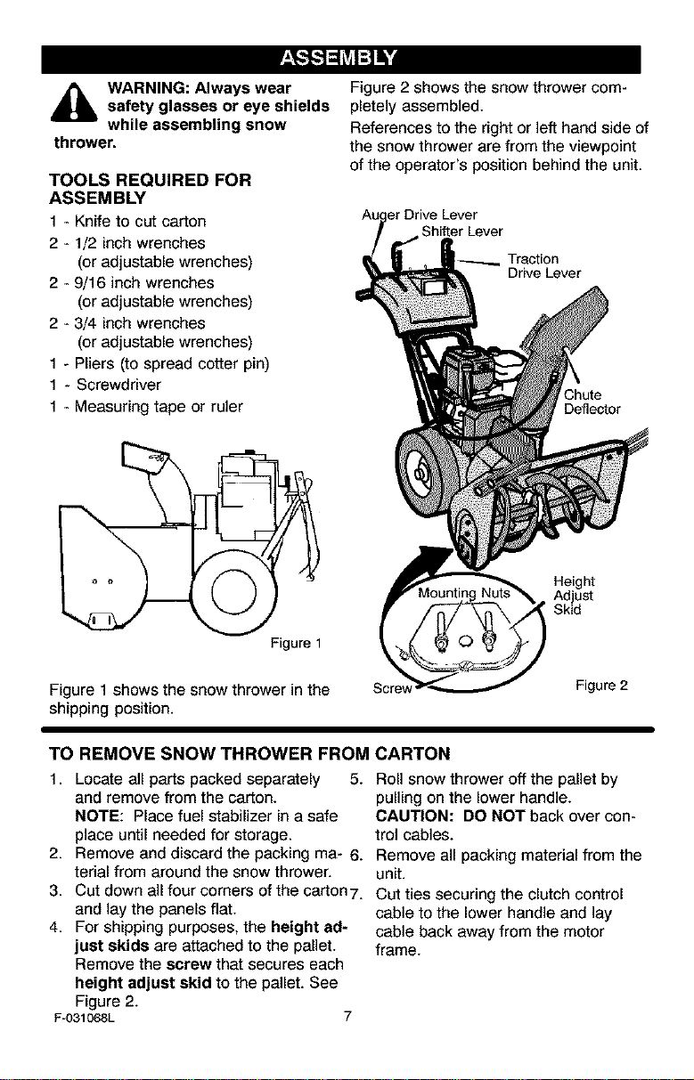
Figure 1
Figure 1 shows the snow thrower in the
shipping position.
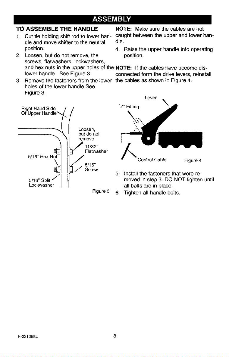
Figure 2 shows the snow thrower com-
pletely assembled.
References to the right or left hand side of
the snow thrower are from the viewpoint
of the operator's position behind the unit.
Lever
Shifter Lever
Traction
Drive Lever
Chute
Deflector
Height
Adjust
Skid
Scre_
Figure2
TO REMOVE SNOW THROWER FROM CARTON
1. Locate all parts packed separately 5.
and remove from the carton.
NOTE: Place fuel stabilizer in a safe
place until needed for storage.
2. Remove and discard the packing mR- 6.
terial from around the snow thrower.
3. Cut down all four corners of the carton 7.
and lay the panels fiat.
4. For shipping purposes, the height ad-
just skids are attached to the pallet.
Remove the screw that secures each
height adjust skid to the pallet. See
Figure 2.
Fu031068L 7
Roll snow thrower off the pallet by
pulling on the lower handle.
CAUTION: DO NOT back over con-
trol cables.
Remove all packing material from the
unit.
Cut ties securing the clutch control
cable to the lower handle and lay
cable back away from the motor
frame.
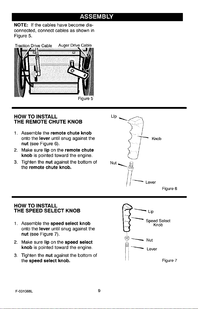
TO ASSEMBLE THE HANDLE NOTE: Make sure the cables are not
1. Cut tie holding shift rod to lower han- caught between the upper and lower han-
dle and move shifter to the neutral die.
position. 4. Raise the upper handle into operating
2. Loosen, but do not remove, the position.
screws, flatwashers, Iockwashers,
and hex nuts in the upper holes of the NOTE: Ifthe cables have become dis-
lower handle. See Figure 3. connected form the drive levers, reinstall
3. Remove the fasteners from the lower the cables as shown in Figure 4.
holes of the lower handle See
Figure 3.
Lever
Hand Side "Z" Fitting
\
5/
5/16" Split _"
Lockwasher
Loosen,
but do not
remove
11/32"
Flatwesher
5/16"
Screw
Figure 3
Control Cable Figure 4
5. Install the fasteners that were re-
moved in step 3. DO NOT tighten until
all bolts are in place.
6. Tighten all handle bolts.
F-O31068L 8
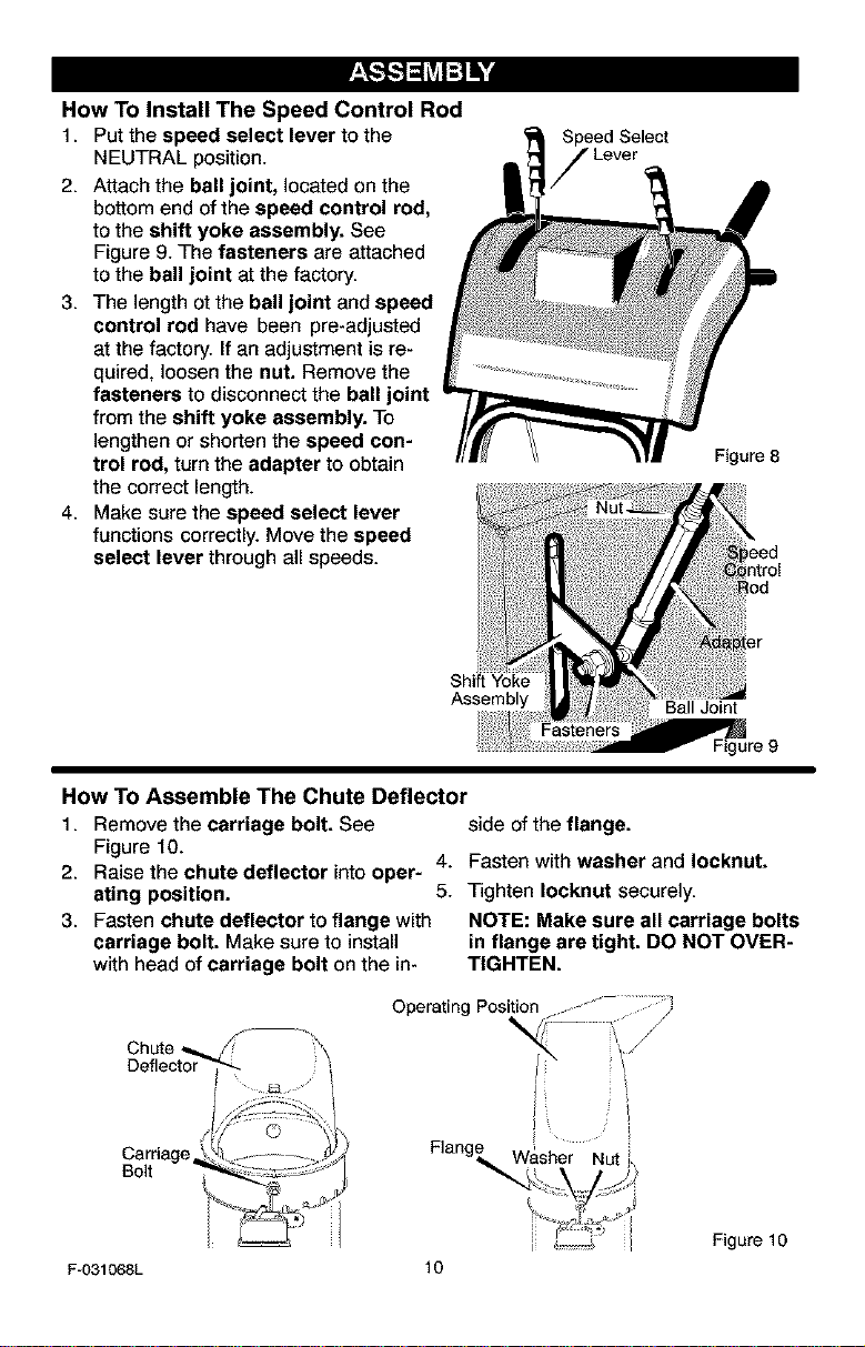
NOTE: If the cables have become dis-
connected, connect cables as shown in
Figure 5.
Traction Drive Cable Auger Drive Cable
Figure 5
HOW TO INSTALL
THE REMOTE CHUTE KNOB
1. Assemble the remote chute knob
onto the lever until snug against the
nut (see Figure 6).
2. Make sure lip on the remote chute
knob is pointed toward the engine.
3. Tighten the nut against the bottom of
the remote chute knob.
Llp
Knob
Lever
Figure 6
HOW TOINSTALL
THE SPEED SELECT KNOB
1. Assemble the speed select knob
onto the lever until snug against the
nut (see Figure 7).
2. Make sure lip on the speed select
knob is pointed toward the engine.
3. Tighten the nut against the bottom of
the speed select knob.
_ _"-"'_ Lip
I _-"_ Speed Select
[_ Knob
, _ Nut
Lever
[ Figure 7
F-031068L 9
How To Install The Speed Control Rod
1. Put the speed select lever to the
NEUTRAL position.
2. Attach the ball joint, located on the
bottom end of the speed control rod,
to the shift yoke assembly. See
Figure 9. The fasteners are attached
to the ball joint at the factory.
3. The length otthe ball joint and speed
control rod have been pre-adjusted
at the factory. If an adjustment is re-
quired, loosen the nut. Remove the
fasteners to disconnect the ball joint
from the shift yoke assembly. To
lengthen or shorten the speed con-
trol rod, turn the adapter to obtain
the correct length.
4. Make sure the speed select lever
functions correctly. Move the speed
select lever through all speeds.
Speed Select
Figure 8
Assembly Ball Joint
Fasteners
Figure 9
How To Assemble The Chute Deflector
1. Remove the carriage bolt. See side of the flange.
Figure 10.
4. Fasten with washer and Iocknut.
2. Raise the chute deflector into oper-
ating position. 5. Tighten Iocknut securely.
3. Fasten chute deflector to flange with NOTE: Make sure all carriage bolts
carriage bolt. Make sure to install in flange are tight. DO NOT OVER-
with head of carriage bolt on the in- TIGHTEN.
J_
Figure 10
F-031068L 10
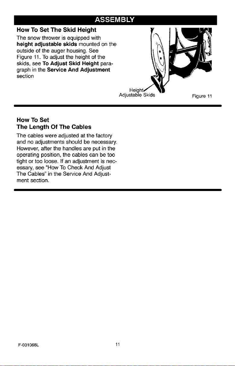
How To Set The Skid Height
The snow thrower is equipped with
height adjustable skids mounted on the
outside of the auger housing. See
Figure 11. To adjust the height of the
skids, see To Adjust Skid Height para-
graph in the Service And Adjustment
section
AdjL
Figure11
How To Set
The Length Of The Cables
The cables were adjusted at the factory
and no adjustments should be necessary.
However, after the handles are put in the
operating position, the cables can be too
tight or too loose. If an adjustment is nec-
essary, see "How To Check And Adjust
The Cables" in the Service And Adjust-
ment section.
F-031068L 11
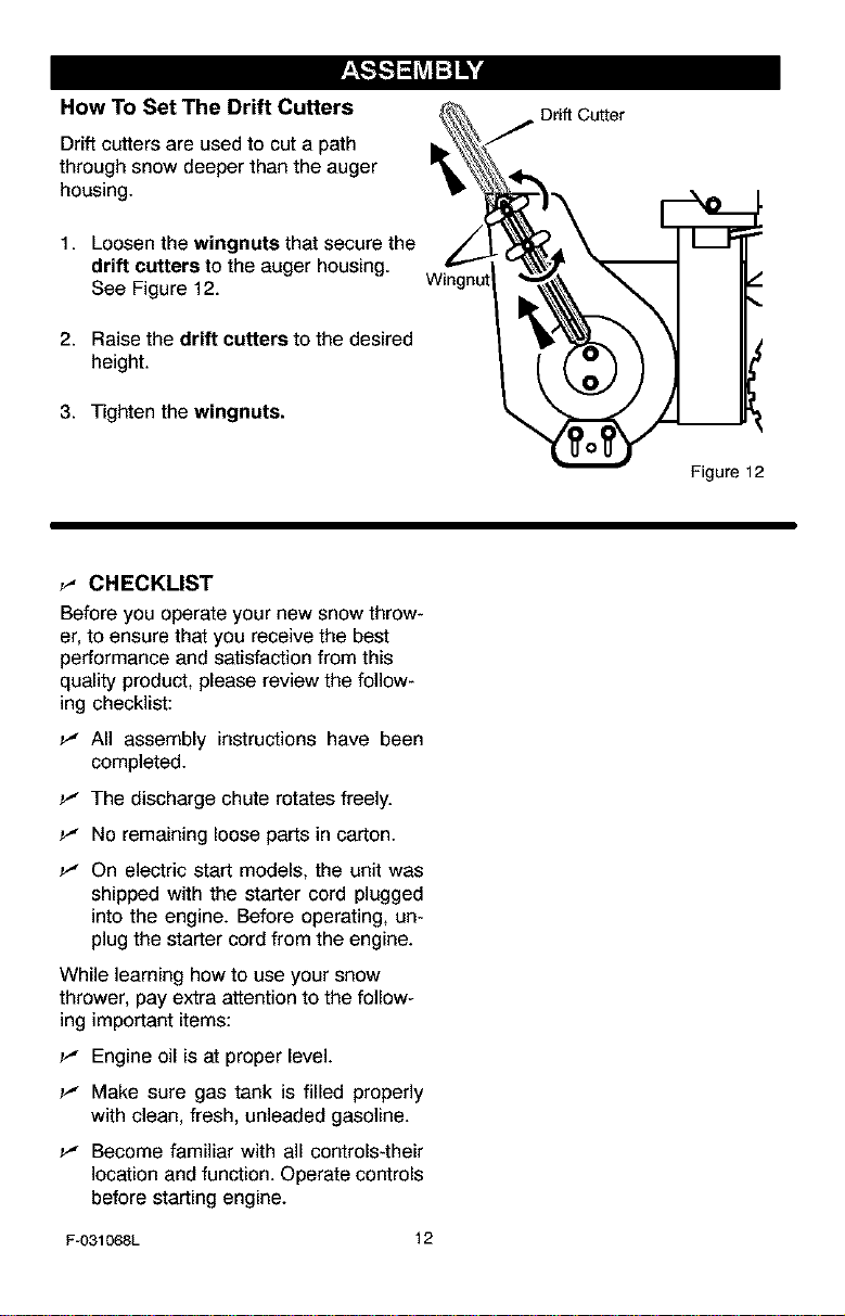
How To Set The Drift Cutters
Drift cutters are used to cut a path
through snow deeper than the auger
housing.
1. Loosen the wingnuts that secure the
drift cutters to the auger housing.
See Figure 12.
2. Raise the drift cutters to the desired
height.
3. Tighten the wingnuts.
Wingnul
Drift Cutter
Figure 12
_" CHECKLIST
Before you operate your new snow throw-
er, to ensure that you receive the best
performance and satisfaction from this
quality product, please review the follow-
ing checklist:
_" All assembly instructions have been
completed.
_" The discharge chute rotates freely.
No remaining loose parts in carton.
_" On electric start models, the unit was
shipped with the starter cord plugged
into the engine. Before operating, un-
plug the starter cord from the engine.
While learning how to use your snow
thrower, pay extra attention to the follow-
ing important items:
_" Engine oil is at proper level.
_" Make sure gas tank is filled properly
with clean, fresh, unleaded gasoline.
_" Become familiar with all controls-their
location and function. Operate controls
before starting engine.
Fu031068L 12
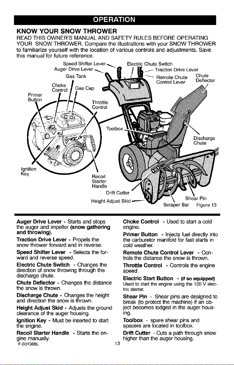
KNOW YOUR SNOW THROWER
READ THIS OWNER'S MANUAL AND SAFETY RULES BEFORE OPERATING
YOUR SNOW THROWER. Compare the illustrations with your SNOW THROWER
to familiarize yourself with the location of various controls and adjustments. Save
this manual for future reference.
Electric Chute Switch
Auger Drive Lever_.
mq
Gas Tank
_ Remote Chute
Chute
Deflector
Choke
Control
Primer
Button
Discharge
Chute
ignition
Key
Starter
Handle
=rPin
Height Adjust Skid _-
Bar Figure 13
Auger Drive Lever - Starts and stops
the auger and impeller (snow gathering
and throwing).
Traction Drive Lever - Propels the
snow thrower forward and in reverse.
Speed Shifter Lever - Selects the for-
ward and reverse speed.
Electric Chute Switch - Changes the
direction of snow throwing through the
discharge chute.
Chute Deflector - Changes the distance
the snow is thrown.
Discharge Chute - Changes the height
and direction the snow is thrown.
Height Adjust Skid - Adjusts the ground
clearance of the auger housing.
Ignition Key - Must be inserted to start
the engine.
Recoil Starter Handle - Starts the en-
gine manually.
F-031068L
13
Choke Control - Used to start a cold
engine.
Primer Button - Injects fuel directly into
the carburetor manifold for fast starts in
cold weather.
Remote Chute Control Lever - Con-
trols the distance the snow is thrown.
Throttle Control - Controls the engine
speed.
Electric Start Button - (ifso equipped)
Usedto startthe engine usingthe 120 V elec-
tric starter.
Shear Pin - Shear pins are designed to
break (to protect the machine) if an ob-
iect becomes lodged in the auger hous-
ing.
Toolbox - spare shear pins and
spacers are located intoolbox.
Drift Cutter -Cuts a path through snow
higher than the auger housing.

Theoperationofanysnowthrowercan
resultinforeignobjectsbeingthrown
intotheeyes,whichcanresultinse-
vereeyedamage.Alwayswearsafety
glassesoreyeshieldswhileoperating
thesnowthrower.
Werecommendstandardsafety
glassesorawidevisionsafetymaskfor
overyourglasses.
,_ WARNING: Read Owner's
Manual before operating
machine. Never direct dis-
charge toward bystanders. Stop the
engine before unclogging discharge
chute or auger housing and before
leaving the machine.
TO STOP YOUR
SNOW THROWER
1. To stop throwing snow, release the
auger drive lever. See Figure 14.
2. To stop the wheels, release the
traction drive lever.
3. To stop the engine, push the
throttle control lever to off and pull
out the ignition key.
Auger Drive Lever
\
TO CONTROL SNOW DISCHARGE
1. Move the electric chute switch to
set the direction (left to right) of the
snow throwing.
2. Push the remote chute lever for-
ward to discharge the snow down.
Pull the remote chute lever back to
discharge the snow high and far.
HOW TO MOVE
FORWARD AND BACKWARD
1. To move the snow thrower forward,
engage the traction drive lever
(left hand). As the snow thrower
starts to move forward, push the
shift lever to the desired speed.
Maintain a firm hold on the handles
and guide the snow thrower along
the clearing path. Do not attempt to
push the snow thrower.
2. To move the snow thrower back-
ward, pull the shift lever to the re-
verse position.
TO THROW SNOW
1. Push down the auger driver lever
(right hand). See Figure 14.
2. Release to stop throwing snow.
Shift Lever TractionDrive Lever
Remote Chute Lever
Figure 14
F-031068L 14
HOW TO USE
THE WHEEL LOCKOUT
Each wheel is secured to the axle with
a lockout pin. See Figure 15. The unit
was shipped with the lockout pin in the
locked position. For ease of maneuver-
ability, disconnect the lockout pin as fol-
lows.
1. Pull the knob out to disengage the
lockout pin.
2. To lock in the disengaged position,
turn the knob 1/4 turn (90 degrees).
Knob
Wheel Lockout
Figure15
HOW TOUSE THE HEATED
GRIPS
,_ WARNING: Heated grips are
designed for use when the tem-
perature is below 32 degrees.
Do not turn on electric grips if tempera-
ture is above 32 degrees.
When the temperature falls below 32 de-
grees, use the heated grips to keep your
hands warm. Move the heated grip switch
to the ON position (see Figure 14). It will
take a couple of minutes for the grips to be-
come warm. Because heated grips can be-
come very warm, we recommend that you
wear gloves. If you notice that the grips are
too warm, turn off heated grips.
BEFORE STARTING THE ENGINE
1. Before you service or start the en-
gine, familiarize yourself with the
snow thrower. Be sure you under-
stand the function and location of all
controls.
2. Check the tension of clutch cable
before starting the engine. See To
Adjust The Control Cable para-
graph in the Service & Adjust-
ments section of this manual.
3. Be sure that all fasteners are tight.
4. Make sure the height adjust skids
are properly adjusted. See To Ad-
just Skid Height paragraph in the
Service & Adjustments section of
this manual.
5. Checktire pressure (14-17
pounds). Do not exceed maximum
amount of pressure.
CHECK THE OIL:
NOTE: The engine was shipped from
the factory filled with oil. Check the lev-
el of the oil. Add oil as needed.
F-031068L
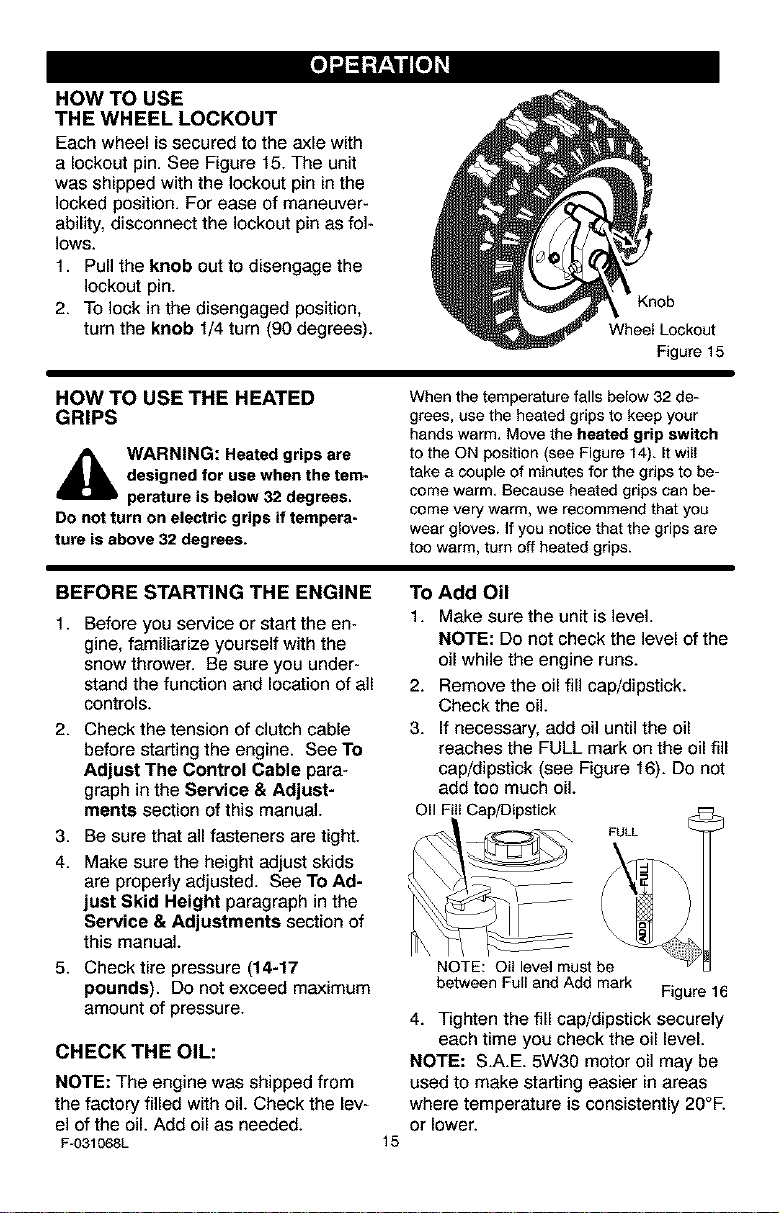
TO Add Oil
1. Make sure the unit is level.
NOTE: Do not check the level of the
oil while the engine runs.
2. Remove the oil fill cap/dipstick.
Check the oil.
3. If necessary, add oil untilthe oil
reaches the FULL mark on the oil fill
cap/dipstick (see Figure 16). Do not
add too much oil.
OII Fill Cap/Dipstick
FULL
15
NOTE: Oil level must be
between Full and Add mark Figure 16
4. Tighten the fill cap/dipstick securely
each time you check the oil level.
NOTE: S.A.E. 5W30 motor oil may be
used to make starting easier in areas
where temperature is consistently 20°F.
or lower.
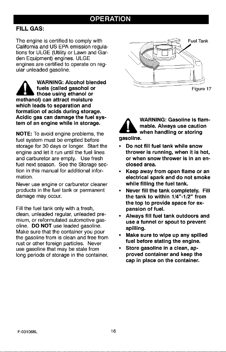
FILL GAS:
The engine is certified to comply with
California and US EPA emission regula-
tions for ULGE (Utility or Lawn and Gar-
den Equipment) engines. ULGE
engines are certified to operate on reg-
ular unleaded gasoline.
_lb ARNING: Alcohol blended
fuels (called gasohol or
those using ethanol or
methanol) can attract moisture
which leads to separation and
formation of acids during storage.
Acidic gas can damage the fuel sys-
tem of an engine while in storage.
NOTE: To avoid engine problems, the
fuel system must be emptied before
storage for 30 days or longer. Start the
engine and let it run until the fuel lines
and carburetor are empty. Use fresh
fuel next season. See the Storage sec-
tion in this manual for additional infor-
mation.
Never use engine or carburetor cleaner
products in the fuel tank or permanent
damage may occur.
Fill the fuel tank only with a fresh,
clean, unleaded regular, unleaded pre-
mium, or reformulated automotive gas-
oline. DO NOT use leaded gasoline.
Make sure that the container you pour
the gasoline from is clean and free from
rust or other foreign particles. Never
use gasoline that may be stale from
long periods of storage in the container.
Fuel Tank
Figure 17
_lb ARNING: Gasoline is flam-
mable. Always use caution
when handling or storing
gasoline.
• Do not fill fuel tank while snow
thrower is running, when it is hot,
or when snow thrower is in an en-
closed area.
• Keep away from open flame or an
electrical spark and do not smoke
while filling the fuel tank.
• Never fill the tank completely. Fill
the tank to within 1/4"-1/2" from
the top to provide space for ex-
pansion of fuel.
• Always fill fuel tank outdoors and
use a funnel or spout to prevent
spilling.
• Make sure to wipe up any spilled
fuel before stating the engine.
• Store gasoline in a clean, ap-
proved container and keep the
cap in place on the container.
F-031068L 16
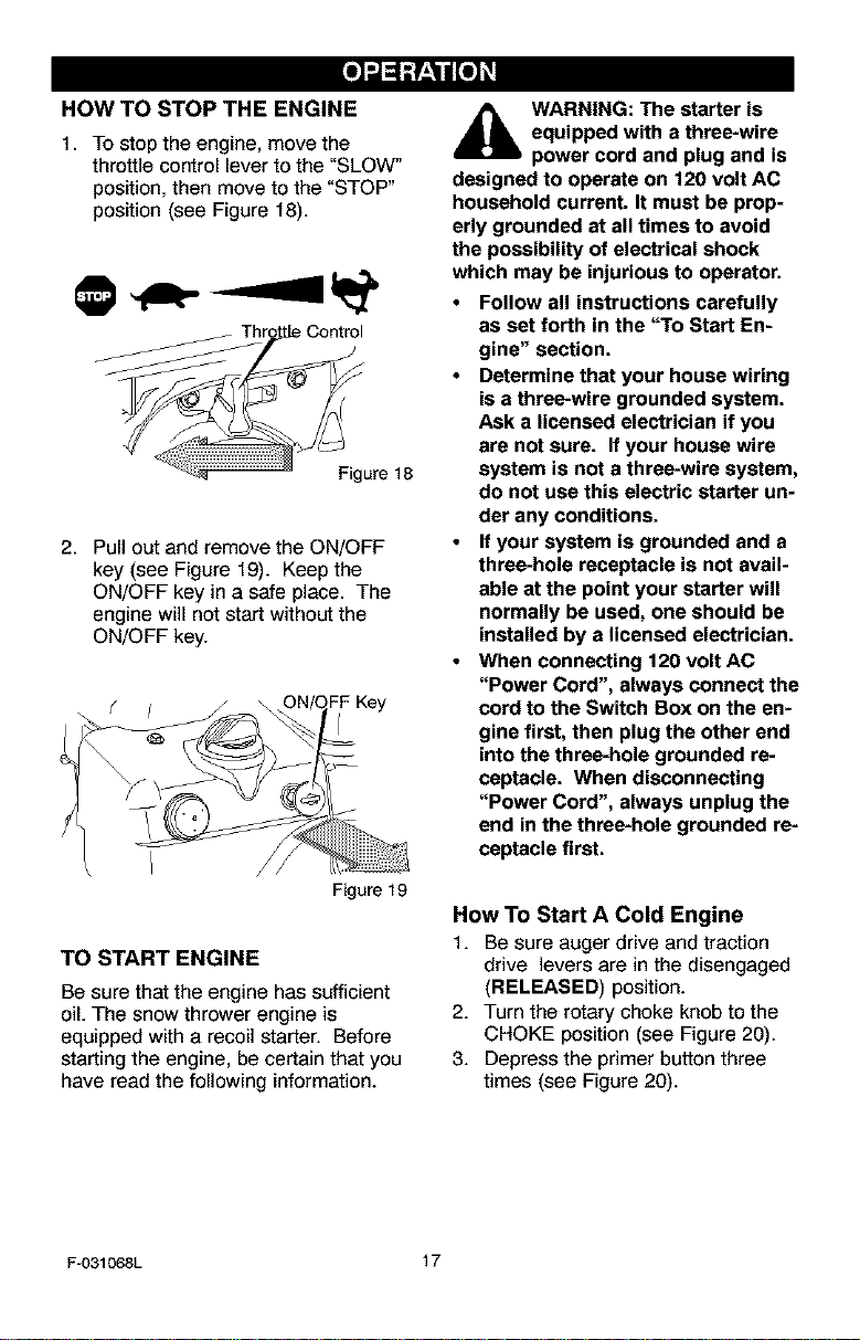
HOW TO STOP THE ENGINE
1. To stop the engine, move the
throttle control lever to the "SLOW"
position, then move to the "STOP"
position (see Figure 18).
Figure 18
2. Pull out and remove the ON/OFF
key (see Figure 19). Keep the
ON/OFF key in a safe place. The
engine will not start without the
ON/OFF key.
Figure 19
TO START ENGINE
Be sure that the engine has sufficient
oil. The snow thrower engine is
equipped with a recoil starter. Before
starting the engine, be certain that you
have read the following information.
_lb ARNING: The starter is
equipped with a three-wire
power cord and plug and is
designed to operate on 120 volt AC
household current. It must be prop-
erly grounded at all times to avoid
the possibility of electrical shock
which may be injurious to operator.
• Follow all instructions carefully
as set forth in the "To Start En-
gine" section.
• Determine that your house wiring
is a three-wire grounded system.
Ask a licensed electrician if you
are not sure. If your house wire
system is not a three-wire system,
do not use this electric starter un-
der any conditions.
• If your system is grounded and a
three-hole receptacle is not avail-
able at the point your starter will
normally be used, one should be
installed by a licensed electrician.
• When connecting 120 volt AC
"Power Cord", always connect the
cord to the Switch Box on the en-
gine first, then plug the other end
into the three-hole grounded re-
ceptacle. When disconnecting
"Power Cord", always unplug the
end in the three-hole grounded re-
ceptacle first.
How TO Start A Cold Engine
1. Be sure auger drive and traction
drive levers are in the disengaged
(RELEASED) position.
2. Turn the rotary choke knob to the
CHOKE position (see Figure 20).
3. Depress the primer button three
times (see Figure 20).
F-031068L 17

Choke Knob Recoil Starter Handle
\\\
4. Move throttle control to "FAST"
position. Operate the engine with
the throttle control in the "FAST"
position (see Figure 21).
Throttle Control
/
Figure 21
5. Remove the ON/OFF keys from the
plastic bag. Insert one of the
ON/OFF keys into the key slot (see
Figure 22). Make sure the key
snaps into place. Do not turn the
ON/OFF key. Keep the second ON/
OFF key in a safe place.
Figure 23
7. (ELECTRIC START) Connect the
power cord to the engine and de-
press the starter button.
Connect
Power Cord
Starter Button
Figure 24
8. As the engine warms up, move
choke lever to "1/2 choke" position.
When engine runs smoothly, move
choke lever to "No Choke" Posi-
tion.
9. Run engine at full throttle "FAST"
when throwing snow.
Allow the engine to warm up for several
minutes before blowing snow in temper-
atures below 0°F.
Figure 22
6. (RECOIL STAR'r) Rapidly pull the
starter handle (see Figure 23). Do
not allow the recoil starter handle
to snap back, but allow it to rewind
slowly while keeping a firm hold on
the starter handle.
F-031068L
18
WARM START
If restarting a warm engine after a short
shutdown, leave choke at "OFF" and do
not push the primer button. If the en-
gine fails to start, follow the Cold Start
instructions.
FROZEN STARTER
If the starter is frozen and will not turn
engine:
1. Pull as much rope out of the starter
as possible.
2. Releasethestarterhandleandletit
snapbackagainstthestarter.Re-
peatuntiltheenginestarts.
Tohelppreventpossiblefreeze-upof
recoilstarterandenginecontrols,pro-
ceedasfollowsaftereachsnowremov-
aljob.
1. Withtheenginerunning,pullthe
starterropehardwithacontinuous
fullarmstrokethreeorfourtimes.
Pullingofstarterropewillproducea
loudclatteringsound.Thisisnot
harmfultotheengineorstarter.
2. Withtheenginenotrunning,wipeall
snowandmoisturefromthecarbu-
retorcoverinareaofcontrollevers.
Alsomovethrottlecontrol,choke
control,andstarterhandleseveral
times.
_lb ARNING: Never run en-
gine indoors or in enclosed,
poorly ventilated areas. En-
gine exhaust contains CARBON
MONOXIDE, AN ODORLESS AND
DEADLY GAS, Keep hands, feet,
hair and loose clothing away from
any moving parts on engine and
snow thrower,
The temperature of muffler and
nearby areas may exceed 150°F,
Avoid these areas,
DO NOT allow children or young
teenagers to operate or be near
snow thrower while it is operat-
ing.
HOW TO REMOVE OBJECTS
FROM AUGER
_lb ARNING: Do not attempt
to remove any item that may
become lodged in auger
without taking the following precau-
tions:
Release auger drive lever.
Move throttle lever to stop position.
Remove (do not turn) ignition key.
Disconnect spark plug wire.
Do not place your hands in the au-
ger or discharge chute. Use a pry
bar.
SNOW THROWING TIPS
1. For maximum snow thrower efficien-
cy in removing snow, adjust ground
speed, NEVER the throttle. Go
slower in deep, freezing or wet
snow. If the wheels slips, reduce
forward speed. The engine is de-
signed to deliver maximum perfor-
mance at full throttle and should be
run at this power setting at all times.
2. Most efficient snow throwing is ac-
complished when the snow is re-
moved immediately after if falls.
3. For complete snow removal, slightly
overlap each path previously taken.
4. The snow should be discharged
down wind whenever possible.
5. For normal usage, set the skids so
that the scraper bar is 1/8" above
the skids. For extremely hard-
packed snow surfaces, adjust the
F-031068L
19
skids upward so that the scraper
bar touches the ground.
6. On gravel or crushed rock surfaces,
set the skids at 1-1/4" below the
scraper bar. See To Adjust Skid
Height paragraph in the Service &
Adjustments section of this manu-
al. Rocks and gravel must not be
picked up and thrown by the ma-
chine.
7. After the snow throwing job has
been completed, allow the engine to
idle for a few minutes, which will
melt snow and accumulated ice off
the engine.
8. Clean the snow thrower thoroughly
after each use.
9. Remove ice and snow accumulation
and all debris from the entire snow
thrower, and flush with water (if pos-
sible) to remove all salt or other
chemicals. Wipe snow thrower dry.
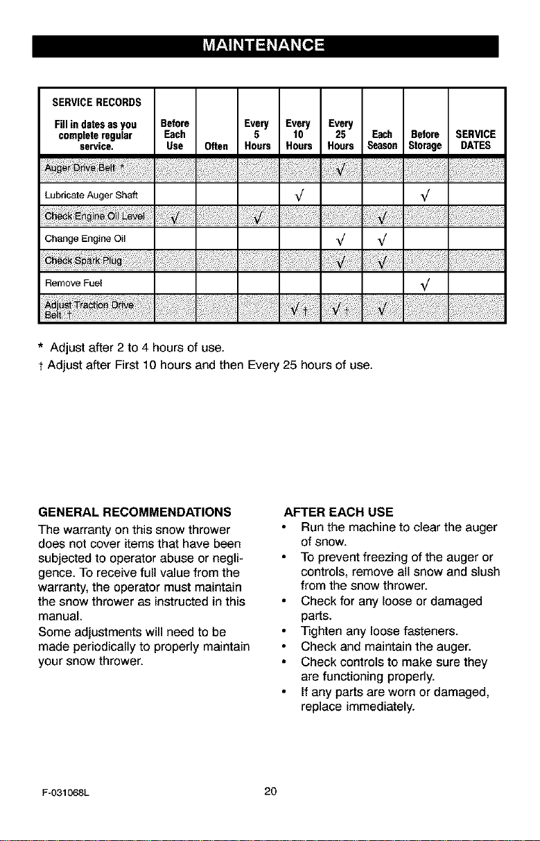
SERVICERECORDS
Fillindatesasyou Before Every Every Every
completeregular Each 5 10 25 Each Before SERVICE
service. Use Often Hours Hours Hours Season Storage DATES
Lubricate Auger Shaft _/ _/
Change Engine Oil _/ _/
Remove Fuel _/
* Adjust after 2 to 4 hours of use.
t Adjust after First 10 hours and then Every 25 hours of use.
GENERAL RECOMMENDATIONS
The warranty on this snow thrower
does not cover items that have been
subjected to operator abuse or negli-
gence. To receive full value from the
warranty, the operator must maintain
the snow thrower as instructed in this
manual.
Some adjustments will need to be
made periodically to properly maintain
your snow thrower.
AFTER EACH USE
Run the machine to clear the auger
of snow.
TO prevent freezing of the auger or
controls, remove all snow and slush
from the snow thrower.
Check for any loose or damaged
parts.
Tighten any loose fasteners.
Check and maintain the auger.
Check controls to make sure they
are functioning properly.
If any parts are worn or damaged,
replace immediately.
F-O31068L 20
ILti_;! I_i i _ r;! _[o]_
PRODUCT SPECIFICATIONS
HORSEPOWER f3 HP
DISPLACEMENT 20.85 cu. in.
GASOLINE 4 quarts
CAPACITY (unleaded)
OIL CAPACITY 5W30
(28oz capacity)
SPARK PLUG: Champion RC12Y(
(Gap .030in.) or
equivalent
VALVE CLEARANCE
Intake: 0.004 - 0.006 In.
Exhaust: 0.009 - 0.011 In.
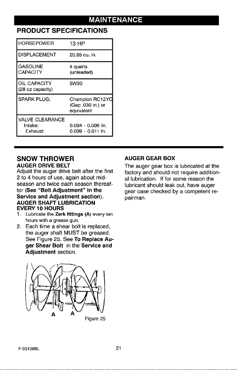
SNOW THROWER
AUGER DRIVE BELT
Adjust the auger drive belt after the first
2 to 4 hours of use, again about mid-
season and twice each season thereaf-
ter (See "Belt Adjustment" in the
Service and Adjustment section).
AUGER SHAFT LUBRICATION
EVERY 10 HOURS
1. Lubricate the Zerk fittings (A) everyten
hourswitha grease gun.
2. Each time a shear bolt is replaced,
the auger shaft MUST be greased.
See Figure 25. See To Replace Au-
ger Shear Bolt in the Service and
Adjustment section.
A
Figure 25
AUGER GEAR BOX
The auger gear box is lubricated at the
factory and should not require addition-
al lubrication, lffor some reason the
lubricant should leak out, have auger
gear case checked by a competent re-
pairman.
F-031068L 21

ENGINE
LUBRICATION
Check the crankcase oil level before
starting the engine and after each five
(5) hours of continuous use. Add S.A.E.
5W30 motor oil as needed. Tighten fill
cap/dipstick securely each time you
check the oil level.
Oil Fill Cap/Dipstick_____
FULL
Oil Drai!_
Plug
Figure 26
Figure 27
Change the oil every twenty-five (25)
hours or at least once a year if the
snow thrower is not used for twenty-five
(25) hours.
TO CHANGE ENGINE OIL
1. Position the snow thrower so that
the oil drain plug is at the lowest
point on the engine.
2. Remove the oil drain plug and the
oil fill cap/dipstick. Drain the oil
into a suitable container.
NOTE: The oil will drain more freely
when the engine is warm.
3. After draining all the oil, reinstall the
oil drain plug securely.
4. Fill the engine crankcase with
S.A.E. 5W30 motor oil, pouring
slowly. DO NOT OVERFILL. See
"To Add Oil" in the Operation Sec-
tion.
SPARK PLUG
Check the spark plug every twenty-five
(25) hours. Replace the spark plug if
the electrodes are pitted or burned or if
the porcelain is cracked.
To access the spark plug, the snow
hood must be removed. See "How To
Remove The Snow Hood" in the Ser-
vice And Adjustment section.
1. Make sure the spark plug is clean.
Clean the spark plug by carefully
scraping the electrodes (do not
sand blast or use a wire brush).
F-031068L
2. Check the spark plug gap with a
feeler gauge and reset gap to 0.30"
if necessary. See Figure 28.
3. Before installing the spark plug,
coat the threads lightly with oil for
easy removal. Tighten the spark
plug to a torque of 15 foot-pounds.
Feeler Gauge
0.030"
22
Spark Plug
Figure 28
_lb ARNING: Always discon-
nect the spark plug wire and
place it where it cannot
make contact with spark plug to pre-
vent accidental starting when mak-
ing any adjustments or repairs.
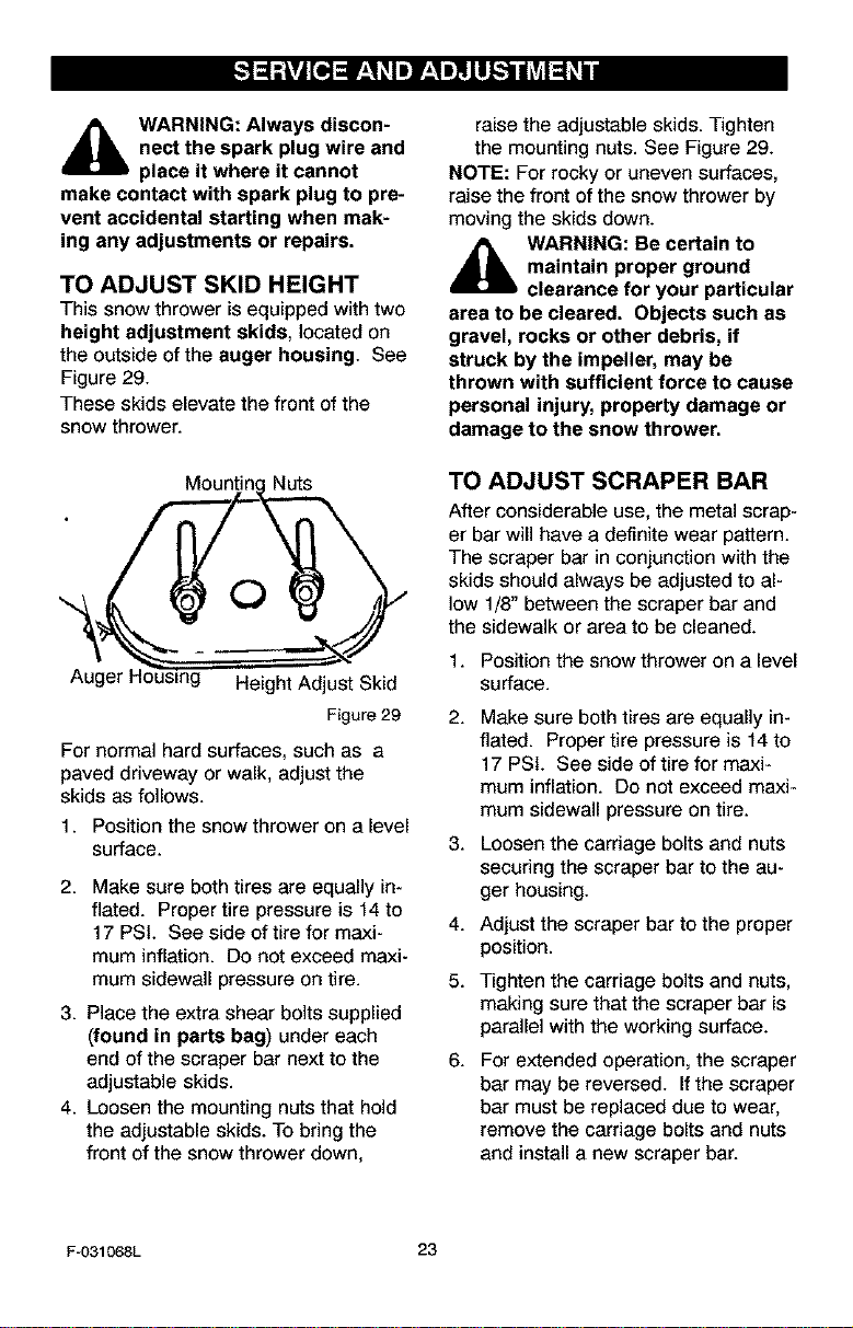
TO ADJUST SKID HEIGHT
This snow thrower is equipped with two
height adjustment skids, located on
the outside of the auger housing. See
Figure 29.
These skids elevate the front of the
snow thrower.
Mountin Nuts
C)
Auger t- Height Adjust Skid
Figure29
For normal hard surfaces, such as a
paved driveway or walk, adjust the
skids as follows.
1. Position the snow thrower on a level
surface.
2. Make sure both tires are equally in-
flated. Proper tire pressure is 14 to
17 PSi. See side of tire for maxi-
mum inflation. Do not exceed maxi-
mum sidewall pressure on tire.
3. Place the extra shear bolts supplied
(found in parts bag) under each
end of the scraper bar next to the
adjustable skids.
4. Loosen the mounting nuts that hold
the adjustable skids. To bring the
front of the snow thrower down,
raise the adjustable skids. Tighten
the mounting nuts. See Figure 29.
NOTE: For rocky or uneven surfaces,
raise the front of the snow thrower by
moving the skids down.
_lb ARNING: Be certain to
maintain proper ground
clearance for your particular
area to be cleared, Objects such as
gravel, rocks or other debris, if
struck by the impeller, may be
thrown with sufficient force to cause
personal injury, property damage or
damage to the snow thrower,
TO ADJUST SCRAPER BAR
After considerable use, the metal scrap-
er bar will have a definite wear pattern.
The scraper bar in conjunction with the
skids should always be adjusted to al-
low 1/8" between the scraper bar and
the sidewalk or area to be cleaned.
1. Position the snow thrower on a level
surface.
2.
3.
4.
5.
6.
Make sure both tires are equally in-
flated. Proper tire pressure is 14 to
17 PSi. See side of tire for maxi-
mum inflation. Do not exceed maxi-
mum sidewall pressure on tire.
Loosen the carriage bolts and nuts
securing the scraper bar to the au-
ger housing.
Adjust the scraper bar to the proper
position.
Tighten the carriage bolts and nuts,
making sure that the scraper bar is
parallel with the working surface.
For extended operation, the scraper
bar may be reversed. If the scraper
bar must be replaced due to wear,
remove the carriage bolts and nuts
and install a new scraper bar.
Fu031068L 23
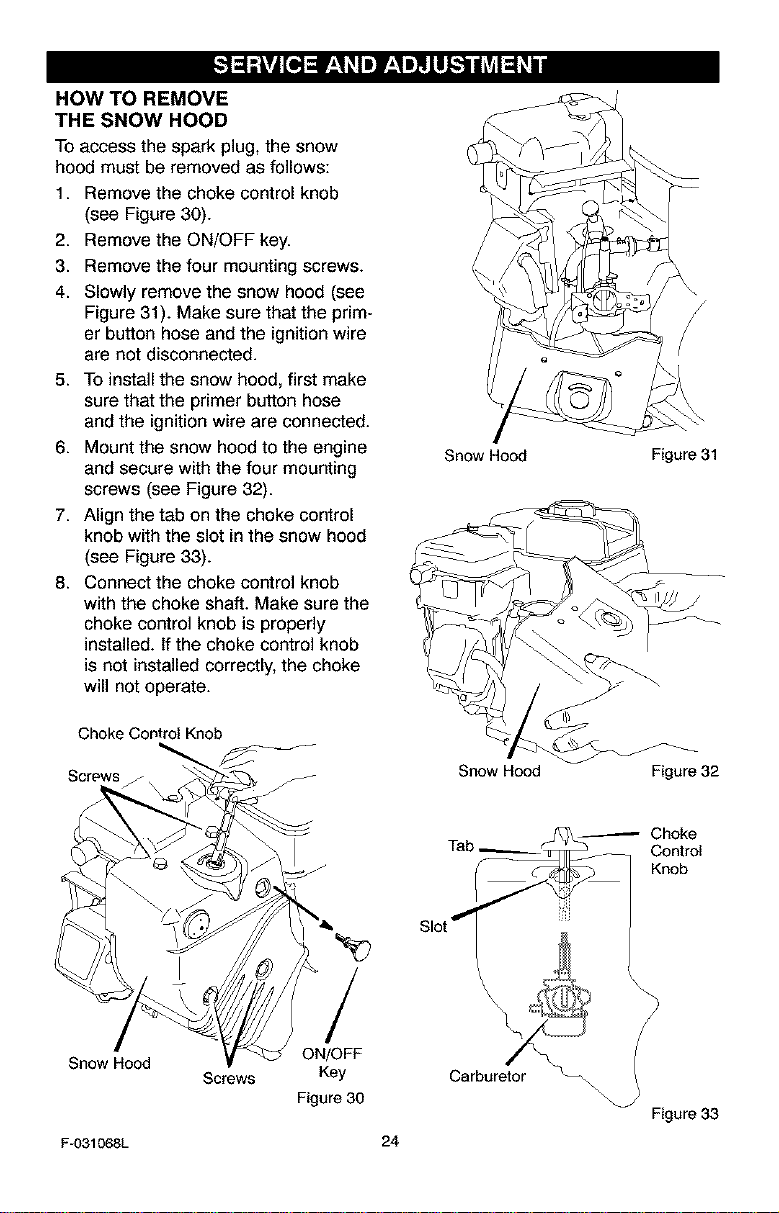
HOW TO REMOVE
THE SNOW HOOD
To access the spark plug, the snow
hood must be removed as follows:
1. Remove the choke control knob
(see Figure 30).
2. Remove the ON/OFF key.
3. Remove the four mounting screws.
4. Slowly remove the snow hood (see
Figure 31). Make sure that the prim-
er button hose and the ignition wire
are not disconnected.
5. To install the snow hood, first make
sure that the primer button hose
and the ignition wire are connected.
6. Mount the snow hood to the engine
and secure with the four mounting
screws (see Figure 32).
7. Align the tab on the choke control
knob with the slot in the snow hood
(see Figure 33).
8. Connect the choke control knob
with the choke shaft. Make sure the
choke control knob is properly
installed. If the choke control knob
is not installed correctly, the choke
will not operate.
Choke Control Knob
Screws
Snow Hood Figure 31
Snow Hood Figure 32
Snow Hood
Screws
F-031068L
/
ON/OFF
Key
Figure 30
--_ Choke
-- Control
Knob
Slot
\
\
24
Carburetor
Figure 33
BELT ADJUSTMENT
Traction Drive Belt
After approximately ten hours of opera-
tion, a new belt will stretch and require
an adjustment of the belt tension. Also,
if your snow thrower experiences a loss
of power under heavy load, check the
condition of the traction drive belt. if it is
damaged or loose, replace it (see "How
To Replace The Belts" in this section of
the manual).
1. Disconnect spark plug wire.
2. Unlock both left and right wheel
locks. See "How To Use The Wheel
Lockout" in the Operation section.
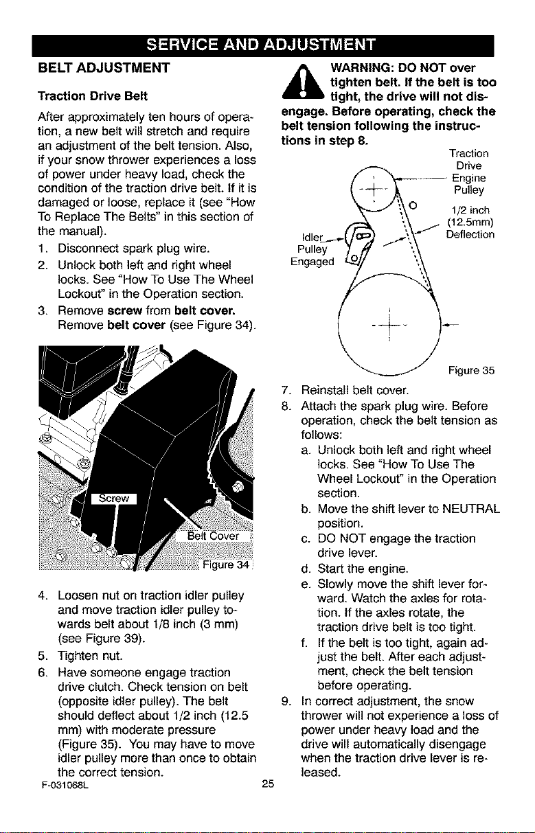
3. Remove screw from belt cover.
Remove belt cover (see Figure 34).
igure 34
4. Loosen nut on traction idler pulley
and move traction idler pulley to-
wards belt about 1/8 inch (3 mm)
(see Figure 39).
5. Tighten nut.
6. Have someone engage traction
drive clutch. Check tension on belt
(opposite idler pulley). The belt
should deflect about 1/2 inch (12.5
ram) with moderate pressure
(Figure 35). You may have to move
idler pulley more than once to obtain
the correct tension.
F-031068L
25
_lb ARNING: DO NOT over
tighten belt. If the belt is too
tight, the drive will not dis-
engage. Before operating, check the
belt tension following the instruc-
tions in step 8.
Traction
Drive
/ Engine
Pu,,ey
, J "t\O 1/2 inch
_-- _ (12.5mm)
Idler__.___(F .j\_J'/" Deflection
Pulley 7OJ " "_
Engaged _J ',
Figure 35
7. Reinstall belt cover.
8. Attach the spark plug wire. Before
operation, check the belt tension as
follows:
a. Unlock both left and right wheel
locks. See "How To Use The
Wheel Lockout" in the Operation
section.
b. Move the shift lever to NEUTRAL
position.
c. DO NOT engage the traction
drive lever.
d. Start the engine.
e. Slowly move the shift lever for-
ward. Watch the axles for rota-
tion. If the axles rotate, the
traction drive belt is too tight.
f. If the belt is too tight, again ad-
just the belt. After each adjust-
ment, check the belt tension
before operating.
9. In correct adjustment, the snow
thrower will not experience a loss of
power under heavy load and the
drive will automatically disengage
when the traction drive lever is re-
leased.
Auger Drive Belt
If your snow blower will not discharge
snow, check the control cable adjust-
ment. If it is correct, then check the
condition of the auger drive belt. If it is
damaged or loose, replace it (see "How
To Replace The Belts" in this section of
the manual).
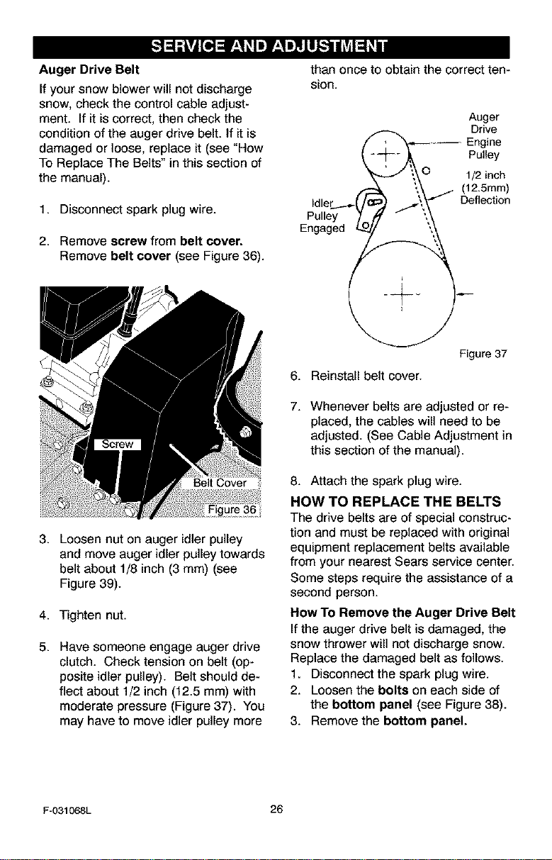
1. Disconnect spark plug wire.
2. Remove screw from belt cover.
Remove belt cover (see Figure 36).
3. Loosen nut on auger idler pulley
and move auger idler pulley towards
belt about 1/8 inch (3 mm) (see
Figure 39).
4. Tighten nut.
5. Have someone engage auger drive
clutch. Check tension on belt (op-
posite idler pulley). Belt should de-
flect about 1/2 inch (12.5 mm) with
moderate pressure (Figure 37). You
may have to move idler pulley more
than once to obtain the correct ten-
sion.
Auger
Drive
_-/_ ._ Pul,ey
.J t\O 1/2 inch
/- \\ (12.5mm)
idler __..._(F .j\_'" Deflection
Pulley 7oJ " "_
Engaged L.._/I_ _
Figure 37
6. Reinstall belt cover.
7. Whenever belts are adjusted or re-
placed, the cables will need to be
adjusted. (See Cable Adjustment in
this section of the manual).
8. Attach the spark plug wire.
HOW TO REPLACE THE BELTS
The drive belts are of special construc-
tion and must be replaced with original
equipment replacement belts available
from your nearest Sears service center.
Some steps require the assistance of a
second person.
How To Remove the Auger Drive Belt
If the auger drive belt is damaged, the
snow thrower will not discharge snow.
Replace the damaged belt as follows.
1. Disconnect the spark plug wire.
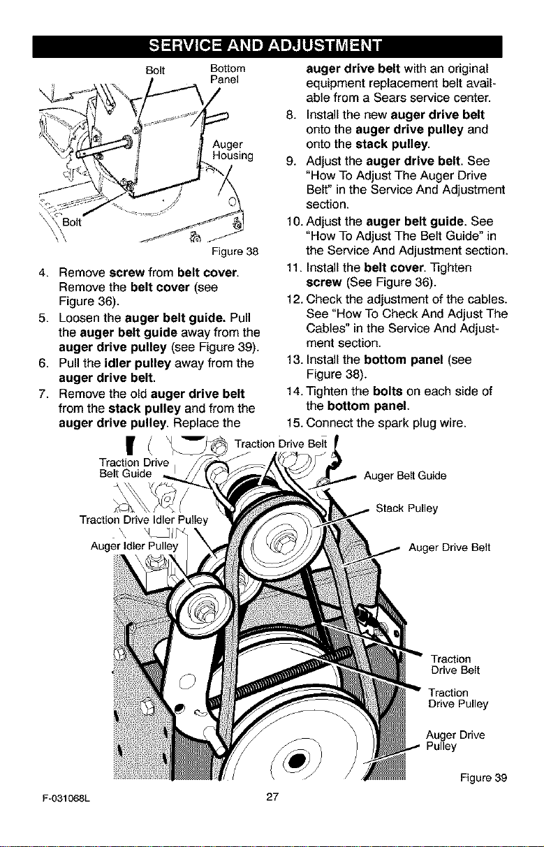
2. Loosen the bolts on each side of
the bottom panel (see Figure 38).
3. Remove the bottom panel.
F-031068L 26
Bolt Bottom
Panel
Auger
Housing
Bolt
Figure 38
4. Remove screw from belt cover.
Remove the belt cover (see
Figure 36).
5. Loosen the auger belt guide. Pull
the auger belt guide away from the
auger drive pulley (see Figure 39).
6. Pull the idler pulley away from the
auger drive belt.
7. Remove the old auger drive belt
from the stack pulley and from the
auger drive pulley. Replace the
I(
Traction Drive
Belt Guide
Traction Drive Idler Pulley
Auger Idler Pulley
auger drive belt with an original
equipment replacement belt avail-
able from a Sears service center.
8. Install the new auger drive belt
onto the auger drive pulley and
onto the stack pulley.
9. Adjust the auger drive belt. See
"How To Adjust The Auger Drive
Belt" in the Service And Adjustment
section.
10. Adjust the auger belt guide. See
"How To Adjust The Belt Guide" in
the Service And Adjustment section.
11. Install the belt cover, qRghten
screw (See Figure 36).
12. Check the adjustment of the cables.
See "How To Check And Adjust The
Cables" in the Service And Adjust-
ment section.
13. Install the bottom panel (see
Figure 38).
14. Tighten the bolts on each side of
the bottom panel.
15. Connect the spark plug wire.
Traction Drive Belt
Auger Belt Guide
Stack Pulley
Auger Drive Belt
Traction
Drive Belt
Traction
Drive Pulley
Auger Drive
Pulley
Figure 39
F-031068L 27
How To Remove
The Traction Drive Belt
Ifthe snow thrower will not move for-
ward, check the traction drive belt for
wear or damage. If the traction drive
belt is worn or damaged, replace the
belt as follows.
1. Disconnect the spark plug wire.
2. Remove the auger drive belt. See
"How To Remove The Auger Drive
Belt" in the Service And Adjustment
section.
3. Loosen the traction drive belt
guide(s). Pull the belt guide(s)
away from the traction drive belt.
4. Loosen the nut on the drive idler
pulley (see Figure 39). Move the
pulley the maximum distance away
from the traction drive belt and
then tighten the nut on the pulley.
5. Remove the old traction drive belt
from the smaller stack pulley.
Then, remove the stack pulley and
old traction drive belt. Replace the
traction drive belt with an original
equipment replacement belt avail-
able from a Sears service center.
6. Install the new traction drive belt
onto the traction drive pulley and
onto the engine shaft..
7. Install the stack pulley onto the en-
gine shaft. Then, mount the trac-
tion drive belt onto the smaller
stack pulley. Tighten the stack
pulley securely to the engine shaft.
8,
Adjust the traction drive belt
guide(s). See "Traction Drive Belt
Guide Adjustment" in the Service
And Adjustment section.
9,
Install and adjust the auger drive
belt. See "How To Remove The Au-
ger Drive Belt" in the Service And
Adjustment section.
10. Adjust the auger belt guide. See
"Auger Belt Guide Adjustment" in
the Service And Adjustment section.
11. Install the bottom panel (see
Figure 38).
12. Tighten the bolts on each side of
the bottom panel.
13.Installthe belt cover.Tighten
screw (seeFigure 36).
14. Check the adjustment of the cables.
See "How To Check And Adjust The
Cables" in the Service And Adjust-
ment section.
15. Connect the spark plug wire.
IMPORTANT: After approximately ten
hours of operation, a new belt will
stretch and require an adjustment of
the belt tension. See "Belt Adjust-
ment" in the Service And Adjustment
section.
F-031068L 28
AUGER BELT GUIDE
ADJUSTMENT
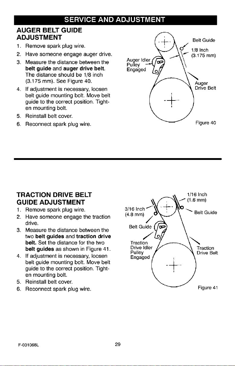
1. Remove spark plug wire.
2. Rave someone engage auger drive.
3. Measure the distance between the
belt guide and auger drive belt.
The distance should be 1/8 inch
(3.175 ram). See Figure 40.
4. If adjustment is necessary, loosen
belt guide mounting bolt. Move belt
guide to the correct position. Tight-
en mounting bolt.
5. Reinstall belt cover.
6. Reconnect spark plug wire.
Auger Idler
Pulley
Engaged
Belt Guide
1/8 Inch
(3.175 mm)
Drive Belt
Figure 40
TRACTION DRIVE BELT
GUIDE ADJUSTMENT
1. Remove spark plug wire.
2. Have someone engage the traction
drive.
3. Measure the distance between the
two belt guides and traction drive
belt. Set the distance for the two
belt guides as shown in Figure 41.
4. If adjustment is necessary, loosen
belt guide mounting bolt. Move belt
guide to the correct position. Tight-
en mounting bolt.
5. Reinstall belt cover.
6. Reconnect spark plug wire.
3/
(4.8 ram)
Belt Guide
Traction
Drive Idler
Pulley
Engaged
1/16 Inch
_ Belt Guide
Traction
Drive Belt
Figure 41
F-031068L 29
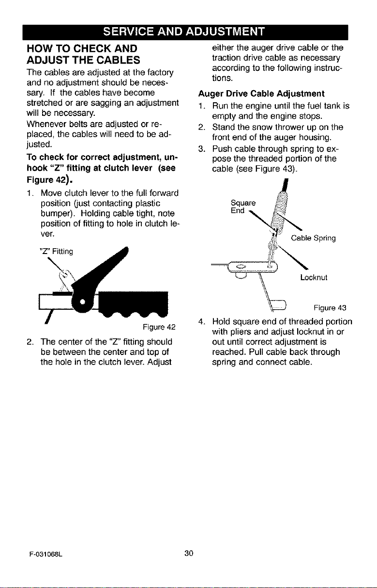
HOW TO CHECK AND
ADJUST THE CABLES
The cables are adjusted at the factory
and no adjustment should be neces-
sary. If the cables have become
stretched or are sagging an adjustment
will be necessary.
Whenever belts are adjusted or re-
placed, the cables will need to be ad-
justed.
To check for correct adjustment, un-
hook "Z" fitting at clutch lever (see
Figure 42).
1. Move clutch lever to the full forward
position (just contacting plastic
bumper). Holding cable tight, note
position of fitting to hole in clutch le-
ver.
"Z" Fitting
Figure 42
2. The center of the "Z" fitting should
be between the center and top of
the hole in the clutch lever. Adjust
either the auger drive cable or the
traction drive cable as necessary
according to the following instruc-
tions.
Auger Drive Cable Adjustment
1. Run the engine until the fuel tank is
empty and the engine stops.
2. Stand the snow thrower up on the
front end of the auger housing.
3. Push cable through spring to ex-
pose the threaded portion of the
cable (see Figure 43).
Square f_
End _ble Spring
Locknut
Figure 43
4. Hold square end of threaded portion
with pliers and adjust Iocknut in or
out until correct adjustment is
reached. Pull cable back through
spring and connect cable.
F-O31068L 30

HOW TO REPLACE
THE AUGER SHEAR BOLT
The augers are secured to the auger
shaft with special shear bolts. These
shear bolts are designed to break and
protect the machine if an object be-
comes lodged in the auger housing. Do
not use a harder bolt as the protection
provided by the shear bolt will be lost.
_lb ARNING: For safety and to
protect the machine, use
only original equipment
shear bolts.
To replace a broken shear bolt, proceed
as follows. Extra shear bolts were pro-
vided in the assembly parts bag.
1. Move the throttle control to the stop
position. Disengage all controls.
2. Disconnect the spark plug wire.
Make sure all moving parts have
stopped.
3. Align the hole in the auger with the
hole in the auger shaft. Install the
new bolt and nut. See Figure 44.
4. Connect the spark plug wire.
TO ADJUST THE CARBURETOR
If you think your carburetor needs ad-
justing, contact your nearest Sears Ser-
vice Center. Engine performance
should not be affected at altitudes up to
7,000 feet. For operation at higher
elevations, contact your nearest Sears
Service Center
IMPORTANT: Never tamper with the
engine governor, which is factory set for
proper engine speed. Over-speeding
the engine above the factory high
speed setting can be dangerous, if you
think the engine-governed high speed
needs adjusting, contact your nearest
Sears Service Center, which has the
proper equipment and experience to
make any necessary adjustments. For
the location of the nearest Sears Ser-
vice Center, call Sears Service at
1-800-4-MY-HOME ®.
F-031068L 31
,_ WARNING: Never store your
snow thrower indoors or in
an enclosed, poorly venti-
lated area. If gasoline remains in the
tank, fumes may reach an open
flame, spark or pilot light from a fur-
nace, water heater, clothes dryer,
cigarette, etc.
To prevent damage (if snow thrower is
not used for more than 30 days) follow
the steps below.
SNOW THROWER
1. Thoroughly cleanthe snow thrower.
2. Lubricateall lubrication points.See
the Maintenance section.
3. Be sure that all nuts, bolts and
screws are securely fastened, in-
spect all visible moving parts for
damage, breakage and wear. Re-
place if necessary.
4. Touch up all rusted or chipped paint
surfaces; sand lightly before paint-
ing.
5. Cover the bare metal parts of the
blower housing auger and the im-
peller with rust preventative, such
as a spray lubricant.
NOTE: A yearly checkup or tune-up by
a Sears service center is a good way of
ensuring that your snow thrower will
provide maximum performance for the
next season.
ENGINE
Gasoline must be removed or treated to
prevent gum deposits from forming in
the fuel tank, filter, hose, and carburetor
during storage. Also, during storage al-
cohol blended gasoline that uses etha-
nol or methanol (sometimes called
gasohol) attracts water, it acts on the
gasoline to form acids which damage
the engine.
1,
2.
3,
4,
5.
Run the engine until the fuel tank is
empty and the engine stops.
If you do not remove the gasoline,
use fuel stabilizer supplied with unit
or purchase Craftsman Fuel Stabi-
lizer No. 3550. Add fuel stabilizer to
any gasoline left in the tank to mini-
mize gum deposits and acids, if the
fuel tank is almost empty, mix stabi-
lizer with fresh gasoline in a sepa-
rate container and add some to the
fuel tank.
Always follow the instructions on the
stabilizer container. After the stabi-
lizer is added to the fuel tank, run
the engine at least ten minutes to
allow the mixture to reach the car-
buretor.
Change the engine oil.
Lubricate the piston/cylinder area.
First, remove the spark plug and
squirt a few drops of clean engine
oil into the spark plug hole. Next,
cover the spark plug hole with a rag
to absorb oil spray. Then, pull two or
three times on the recoil starter rope
to rotate the engine. Finally, install
the spark plug and attach the spark
plug wire.
OTHER
1. If possible,store yoursnowthrower
indoors and cover it to give protec-
tion from dust and dirt.
2. If the snow thrower must be stored
outdoors, put the snow thrower on
blocks to raise it off of the ground.
3. Cover the snow thrower with a suit-
able protective cover that does not
retain moisture. Do not use plastic.
IMPORTANT: Never cover snow
thrower while engine and exhaust areas
are still warm.
F-031068L 32
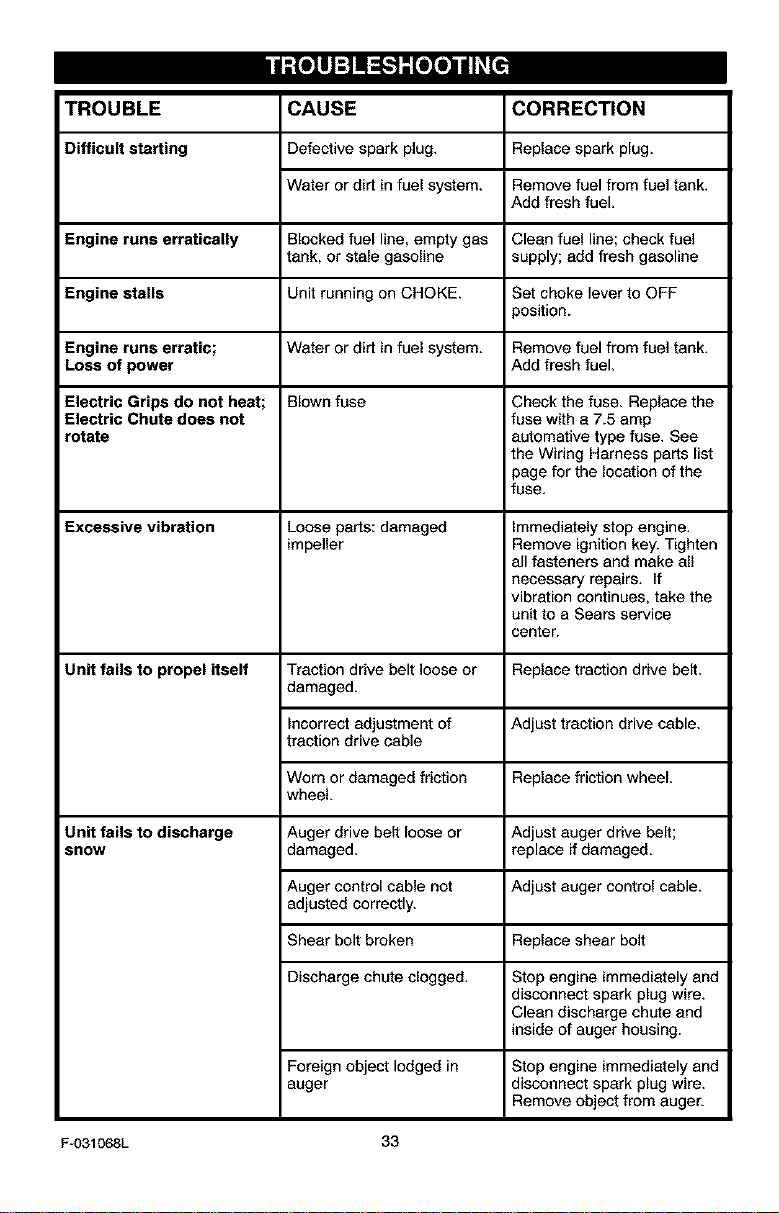
TROUBLE CORRECTION
Difficult starting
CAUSE
Defective spark plug,
Water or dirt in fuel system.
Replace spark plug.
Remove fuel from fuel tank.
Add fresh fuel.
Engine runs erratically Blocked fuel line, empty gas Clean fuel line; check fuel
tank, or stale gasoline supply; add fresh gasoline
Engine stalls Unit running on CHOKE. Set choke lever to OFF
position.
Engine runs erratic; Water or dirt in fuel system. Remove fuel from fuel tank.
Loss of power Add fresh fuel.
Electric Grips do not heat; Blown fuse Check the fuse. Replace the
Electric Chute does not fuse with a 7.5 amp
rotate automative type fuse. See
the Wiring Harness parts list
page for the location of the
fuse.
Excessive vibration Loose parts: damaged Immediately stop engine.
impeller Remove ignition key. Tighten
all fasteners and make all
necessary repairs. If
vibration continues, take the
unit to a Sears service
center.
Unit fails to propel itself Traction drive belt loose or Replace traction drive belt.
damaged.
Incorrect adjustment of
traction drive cable
Worn or damaged friction
wheel.
Auger drive belt loose or
damaged.
Adjust traction drive cable.
Replace friction wheel.
Unit fails to discharge
snow
Adjust auger drive belt;
replace if damaged.
Auger control cable not Adjust auger control cable.
adjusted correctly.
Shear bolt broken Replace shear bolt
Discharge chute clogged. Stop engine immediately and
disconnect spark plug wire.
Clean discharge chute and
inside of auger housing.
Foreign object lodged in
auger
Stop engine immediately and
disconnect spark plug wire.
Remove object from auger.
F-031068L 33
SEARS, ROEBUCK AND CO.
Federal and California Emission Control Systems Limited Warranty
Small Off-Road Engines
CALIFORNIA & US EPA EMISSION
CONTROL WARRANTY STATEMENT
The U. S. Environmental Protection Agency
CEPA"), the California Air Resources Board
CCARB") and Sears, Roebuck and Co. are
pleased to explain the Federal and California
Emission Control Systems Warranty on your
new small off-road engine. In California, new
1995 and later small off-road engines must be
designed, built and equipped to meet the
State's stringent anti-smog standards. In oth-
er states, new 1997 and later model year en-
gines must be designed, built and equipped, at
the time of sale, to meet the U.S. EPA regula-
tions for small non-road engines. Sears, Roe-
buck and Co. will warrant the emission control
system on your small off-road engine for the
periods of time listed below, provided there
has been no abuse, neglect, unapproved mod-
ification, or improper maintenance of your
small off-road engine.
Your emission control system may include
parts such as the carburetor, ignition system
and exhaust system. Also included may be the
compression release system and other emis-
sion-related assemblies.
Where a warrantable condition exists, Sears,
Roebuck and Co. will repair your small off-
road engine at no cost to you for diagnosis,
parts and labor.
MANUFACTURER'SEMISSION
CONTROL SYSTEM WARRANTY
COVERAGE
Emission control systems on 1995 and later
model year California small off-road engines
are warranted for two years as hereinafter
noted. In other states, 1997 and later model
year engines are also warranted for two years.
If, during such warranty period, any emission-
related part on your engine is defective in ma-
terials or workmanship, the part will be
repaired or replaced by Sears, Roebuck and
Co.
OWNER'S WARRANTY
RESPONSIBILITIES
As the small off-road engine owner, you are
responsible for the performance of the re-
F-031068L
quired maintenance listed in your Owner's
Manual, but Sears, Roebuck and Co. will not
deny warranty solely due to the lack of receipts
or for your failure to provide wdtten evidence
of the performance of all scheduled mainte-
nance.
As the small off-road engine owner, you
should, however, be aware that Sears, Roe-
buck and Co. may deny you warranty cover-
age if your small off-road engine or e part
thereof has failed due to abuse, neglect, im-
proper maintenance or unepproved modifica-
tions.
You are responsible for presenting your small
off-road engine to a Sears, Roebuck and Co.
Authodzed Service Outlet as soon as a prob-
lem exists. The warranty repairs should be
completed ina reasonable amount of time, not
to exceed 30 days.
Warranty service can be arranged by contact-
ing either a Sears, Roebuck and Co. Autho-
rized Service Outlet, or by contacting Sears,
Roebuck and Co. at 1-800-473-7247.
34
IMPORTANT NOTE
This warranty statement explains your rights
and obligations under the Emission Control
System Warranty "(ECS Warranty") which is
provided to you by Sears, Roebuck and Co.
pursuant to California law. See also the Sears,
Roebuck and Co. Limited Warranties for
Sears, Roebuck and Co. which is enclosed
therewith on a separate sheet and also is pro-
vided to you by Sears, Roebuck and Co. The
ECS Warranty applies only to the emission
control system of your new engine. To the ex-
tent that there is any conflict in terms between
the ECS Warranty and the Sears, Roebuck
and Co. Warranty, the ECS Warranty shall ap-
ply except in any circumstances in which the
Sears, Roebuck and Co. Warranty may pro-
vide a longer warranty period. Both the ECS
Warranty and the Sears, Roebuck and Co.
Warranty describe important rights and obliga-
tions with respect to your new engine.
Warranty service can only be performed by a
Sears, Roebuck and Co. Authorized Service
Outlet. At the time of requesting warranty ser-
vice, evidence must be presented of the date
of sale to the original purchaser. The perches-
ershallpayanychargesformakingservice
callsand/orfortransportingtheproductsto
andfromtheplacewheretheinspectionand/
orwarrantyworkisperformed.Thepurchaser
shallberesponsibleforanydamageorlossin-
curredinconnectionwiththetransportationof
anyengineoranypart(s)thereofsubmittedfor
inspectionand/orwarrantywork.
Ifyouhaveanyquestionsregardingyourwar-
rantyrightsandresponsibilities,youshould
contactSears,Roebuckand Co. at
1-800-473-7247.
EMISSION CONTROL SYSTEM
WARRANTY
Emission Control System Warranty ("ECS
Warranty") for 1995 and later model year Cali-
fornia small off-road engines (for other states,
1997 and later model year engines):
A. APPLICABILITY: This warranty shall apply
to 1995 and later model year California small
off-raed engines (for other states, 1997 and
later model year engines). The ECS Warranty
Period shall begin on the date the new engine
or equipment is delivered to its original, end-
use purchaser, and shall continue for 24 con-
secutive months thereafter.
B. GENERAL EMISSIONS WARRANTY
COVERAGE: Sears, Roebuck and Co. war-
rants to the original, end-use purchaser of the
new engine or equipment and to each subse-
quent purchaser that each of its small off-road
engines is:
1. Designed, built and equipped so as to con-
form with all applicable regulations adopted by
the Air Resources Board pursuant to its au-
thority in Chapters 1 and 2, Part 5, Division 26
of the Health and Safety Code, and
2. Free from defects in materials and work-
manship which, at any time during the ECS
Warranty Peded, will cause a warranted emis-
sions-related part to fail to be identical in all
material respects to the part as described in
the engine manufacturer's application for certi-
fication.
C. The ECS Warranty only pertains to emis-
sions-related parts on your engine, as follows:
1. Any warranted, emissions-related parts
which are not scheduled for replacement as
required maintenance in the Owner's Manual
shall be warranted for the ECS Warranty Peri-
od. If any such part fails dudng the ECS War-
ranty Period, it shall be repaired or replaced by
F-031068L
35
Sears, Roebuck and Co. according to Subsec-
tion 4 below. Any such part repaired or ra-
placed under the ECS Warranty shall be
warranted for any remainder of the ECS War-
ranty Period.
2. Any warranted, emissions-related part
which is scheduled only for regular inspection
as specified in the Owner's Manual shall be
warranted for the ECS Warranty Period. A
statement in such written instructions to the ef-
fect of "repair or replace as necessary", shall
not reduce the ECS Warranty Period. Any
such part repaired or replaced under the ECS
Warranty shall be warranted for the remainder
of the ECS Warranty Period.
3. Any warranted, emissions-related part
which is scheduled for replacement as re-
quired maintenance in the Owner's Manual,
shall be warranted for the period of time pdor
to the first scheduled replacement point for
that part. If the part fails prior to the first sched-
uled replacement, the part shall be repaired or
replaced by Sears, Roebuck and Co. accord-
ing to Subsection 4 below. Any such emis-
sions-related part repaired or replaced under
the ECS Warranty, shall be warranted for the
remainder of the ECS Warranty Period prior to
the first scheduled replacement point for such
emissions-related part.
4. Repair or replacement of any warranted,
emissions-related part under this ECS War-
ranty shall be performed at no charge to the
owner at a Sears, Roebuck and Co. Autho-
rized Service Outlet.
5. The owner shall not be charged for diagnos-
tic labor which leads to the determination that
a part covered by the ECS Warranty is in fact
defective, provided that such diagnostic work
is performed at a Sears, Roebuck and Co. Au-
thorized Service Outlet.
6. Sears, Roebuck and Co. shall be liable for
damages to other original engine components
or approved modifications proximately caused
by a failure under warranty of an emission-re-
lated part covered by the ECS Warranty.
7. Throughout the ECS Warranty Period,
Sears, Roebuck and Co. shall maintain a sup-
ply of warranted emission-related parts suffi-
cient to meet the expected demand for such
emission-related parts.
8. Any Sears, Roebuck and Co. authorized
and approved emission-related replacement
part may be used in the performance of any
ECS Warranty maintenance or repair and will
be provided withoL_ charge to the owner. Such
useshallnotreduceSears,RoebuckandCo.
ECSWarrantyobligations.
9.Unepprovedadd-onormodifiedpartsmay
notbeusedtomodifyorrepairaSears,Roe-
buckandCo.engine. Such use voids this ECS
Warranty and shall be sufficient grounds for
disallowing an ECS Warranty claim. Sears,
Roebuck and Co. shall not be liable hereunder
for failures of any warranted parts of a Sears,
Roebuck and Co. engine caused by the use of
such an unapproved add-on or modified part.
EMISSION-RELATED PARTS
INCLUDE THE FOLLOWING:
1. Carburetor Assembly and its Internal Com-
ponents
a) Fuel filter
b) Carburetor gaskets
c) Intake pipe
2. Air Cleaner Assembly
a) Air filter element
3. Ignition System, including:
a) Spark plug
b) Ignition module
c) Flywheel assembly
4. Catalytic Muffler (if so equipped)
a) Muffler gasket (if so equipped)
b) Exhaust manifold (if so equipped)
5. Crankcase Breather Assembly and its
Components
a) Breather connection tube
10/22/99 EPA/CARB
Sears, Roebuck and Co., Hoffman Estates, IL 60179 U.S.A.
F-031068L 36

F-O31068L 37

F-O31068L 38
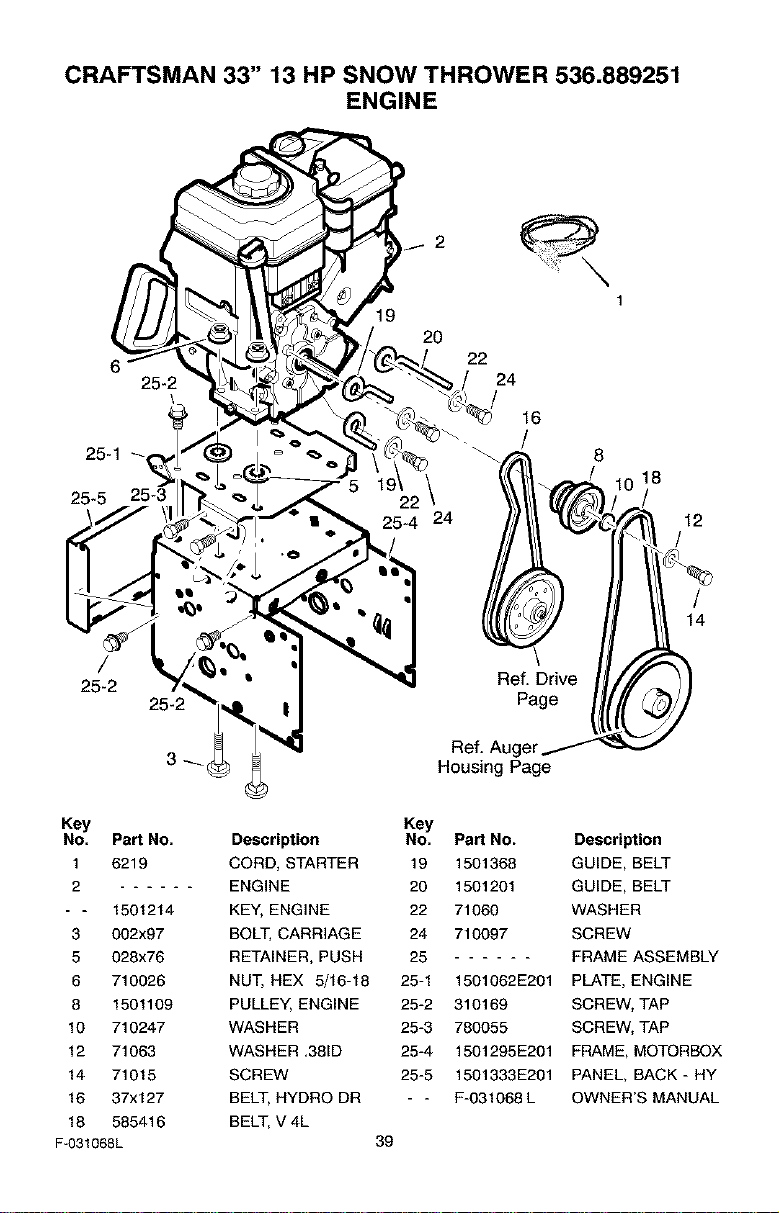
CRAFTSMAN 33" 13 HP SNOW THROWER 536.889251
ENGINE
19
20
6 22
25-2 24
25-1
25-5 25-3
25-4 24
/
25-2
25-2
16
/
8
Ref. Drive
Page
18
12
/
/
14
Housing Page
Key
No. Part No.
1 6219
2
- - 1501214
3 002x97
5 028x76
6 710026
8 1501109
10 710247
12 71063
14 71015
16 37x127
18 585416
F-031068L
Key
Description No. Part No.
CORD, STARTER 19 1501368
ENGINE 20 1501201
KEY, ENGINE 22 71060
BOLT, CARRIAGE 24 710097
RETAINER, PUSH 25
NUT, HEX 5/16-18 25-1 1501062E201
PULLEY, ENGINE 25-2 310169
WASHER 25-3 780055
WASHER ,38_D 25-4 1501295E201
SCREW 25-5 1501333E201
BELT, HYDRO DR - - E-031068 L
BELT, V 4L
39
Description
GUIDE, BELT
GUIDE, BELT
WASHER
SCREW
FRAME ASSEMBLY
PLATE, ENGINE
SCREW, TAP
SCREW, TAP
FRAME, MOTORBOX
PANEL, BACK - HY
OWNER'S MANUAL
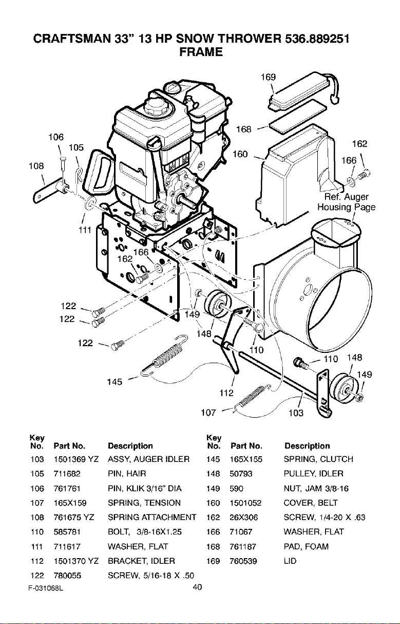
CRAFTSMAN 33" 13 HP SNOW THROWER 536.889251
FRAME
106
\ 105
/
111
169
168
162
Ref. Auger
Key
No. Part No.
103 1501369 YZ
105 711682
106 761761
107 165X159
108 761675 YZ
110 585781
111 711617
112 1501370 YZ
122 780055
F-031068L
145
/
112
107
Key
Description No. Part No.
ASSY, AUGER IDLER 145 165X155
PIN, HAiR 148 50793
PIN, KLIK 3/16" DIA 149 590
SPRING, TENSION 160 1501052
SPRING ATTACHMENT 162 26X306
BOLT, 3/8-16Xl.25 166 71067
WASHER, FLAT 168 761187
BRACKET, IDLER 169 760539
SCREW, 5/16-18 X ,50
40
148
149
103
Description
SPRING, CLUTCH
PULLEY, IDLER
NUT, JAM 3/8-16
COVER, BELT
SCREW, 1/4-20 X ,63
WASHER, FLAT
PAD, FOAM
LID
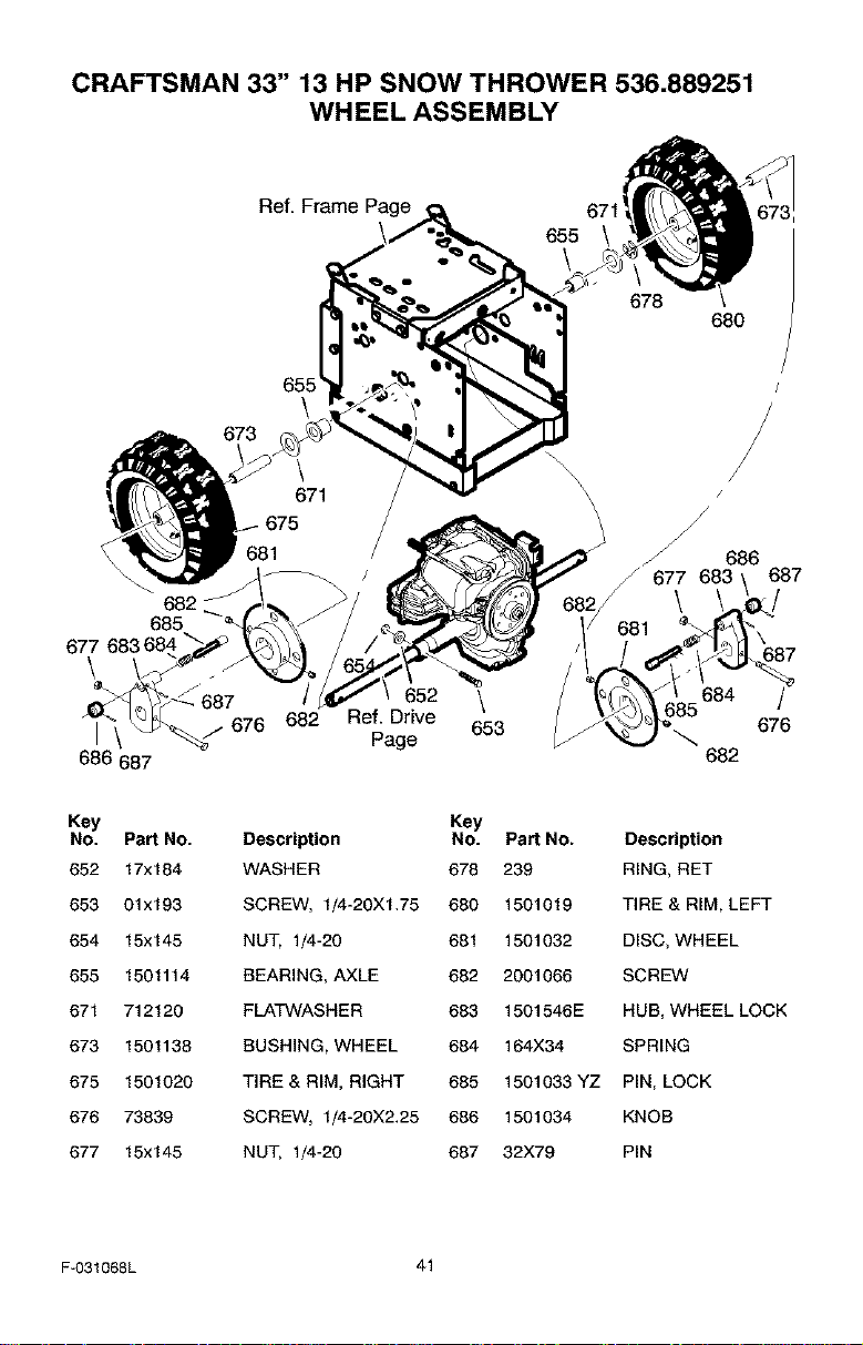
CRAFTSMAN 33" 13 HP SNOW THROWER 536.889251
WHEEL ASSEMBLY
Ref. Frame Page
678
680
655
\
682 __
685
686 687
_/676 682 Ref. Drive
Page
\ /
h
\
\
686
_" 677 683
\
681
\ 684
653
682
687
87
7
676
Key
No. Part No.
652 17x184
653 01x193
654 15x145
655 1501114
671 712120
673 1501138
675 1501020
676 73839
677 15x145
Description
WASHER
SCREW, 1/4-20XI.75
NUT, 1/4-20
BEARING, AXLE
FLATWASHER
BUSHING, WHEEL
TIRE & RIM, RIGHT
SCREW, 1/4-20X2.25
NUT, 1/4-20
Key
No. Part No. Description
678 239 RING, RET
689 1501019 TIRE & RIM, LEFT
681 1591032 DISC, WHEEL
682 2001066 SCREW
683 1501546E HUB, WHEEL LOCK
684 164)(34 SPRING
685 1501033 YZ PIN, LOCK
686 1501034 KNOB
687 32X79 PIN
F-031068L 41
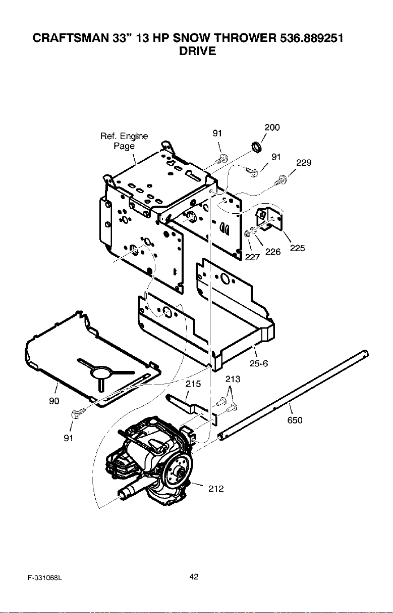
CRAFTSMAN 33" 13 HP SNOW THROWER 536.889251
DRIVE
Ref. Engine
Page
91
\
200
91
229
'226 225
90
/
91
25-6
213
650
212
F-031068L 42
CRAFTSMAN 33" 13 HP SNOW THROWER 536.889251
DRIVE
Key No. Part No. Description
90 1501311E701 COVER, BOTTOM
91 310169 SCREW, 1/4-20 X 0.62
25-6 1501334E201 FRAME, EXTENSION - HYDRO
200 1501496 PLUG, HEYCO
212 TRANSMISSION, HYDRO
213 021Xll RIVET, BUND
215 1501366 ARM, CONTROL EXTENSION
225 1501361 BRACKET, DRIVE CABLE
226 71063 WASHER, LOCK
227 71045 NUT, HEX JAM - 3/8-16
229 025X19 SCREW
650 1501365 AXLE, WHEEL
F-031068L 43
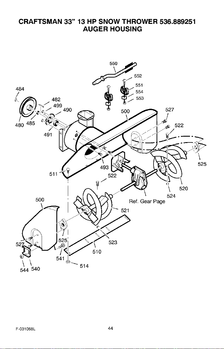
CRAFTSMAN 33" 13 HP SNOW THROWER 536.889251
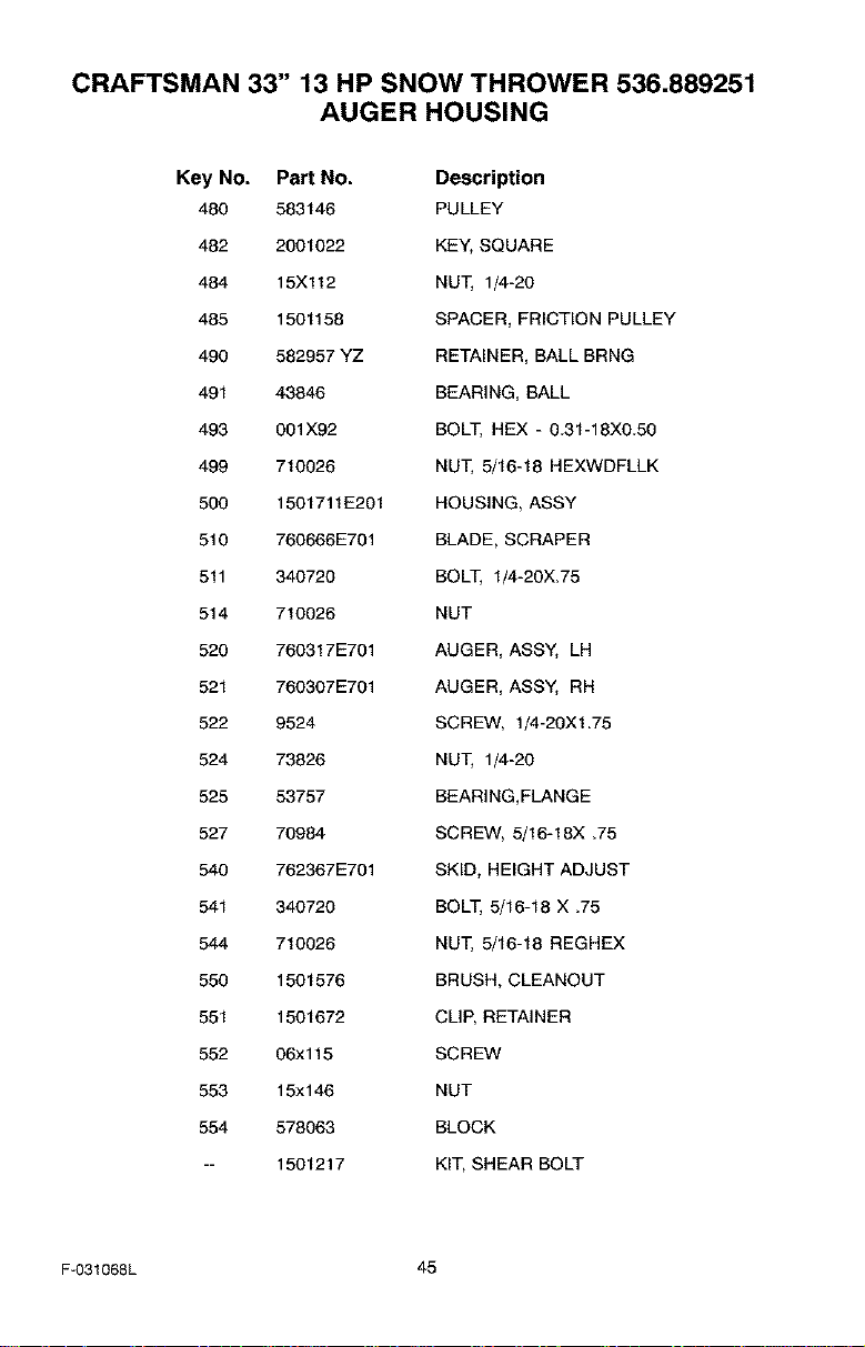
AUGER HOUSING
484
480
482
499
490
491
527
522
500
522
\ 520
524
Ref. Gear Page
521
\
525
\\
544 540
523
510
F-031068L 44
CRAFTSMAN 33" 13 HP SNOW THROWER 536.889251
AUGER HOUSING
Key No. Part No. Description
480 583146 PULLEY
482 2001022 KEY, SQUARE
484 15Xl12 NUT, 1/4-20
485 1501158 SPACER, FRICTION PULLEY
490 582957 YZ RETAINER, BALL BRNG
491 43846 BEARING, BALL
493 001X92 BOLT, HEX - 0.31-18X0.50
499 710026 NUT, 5/16-18 HEXWDFLLK
500 1501711E201 HOUSING, ASSY
510 760666E701 BLADE, SCRAPER
511 340720 BOLT, 1/4-20X.75
514 710026 NUT
520 760317E701 AUGER, ASSY, LH
521 760307E701 AUGER, ASSY, RH
522 9524 SCREW, 1/4-20X1.75
524 73826 NUT, 1/4-20
525 53757 BEARING,FLANGE
527 70984 SCREW, 5/16-18X _75
540 762367E701 SKID, HEIGHT ADJUST
541 340720 BOLT, 5/16-18 X .75
544 710026 NUT, 5/16-18 REGHEX
550 1501576 BRUSH, CLEANOUT
551 1501672 CLIP, RETAINER
552 06x115 SCREW
553 15xl 46 NUT
554 578063 BLOCK
-- 1501217 KIT, SHEAR BOLT
F-031068L 45
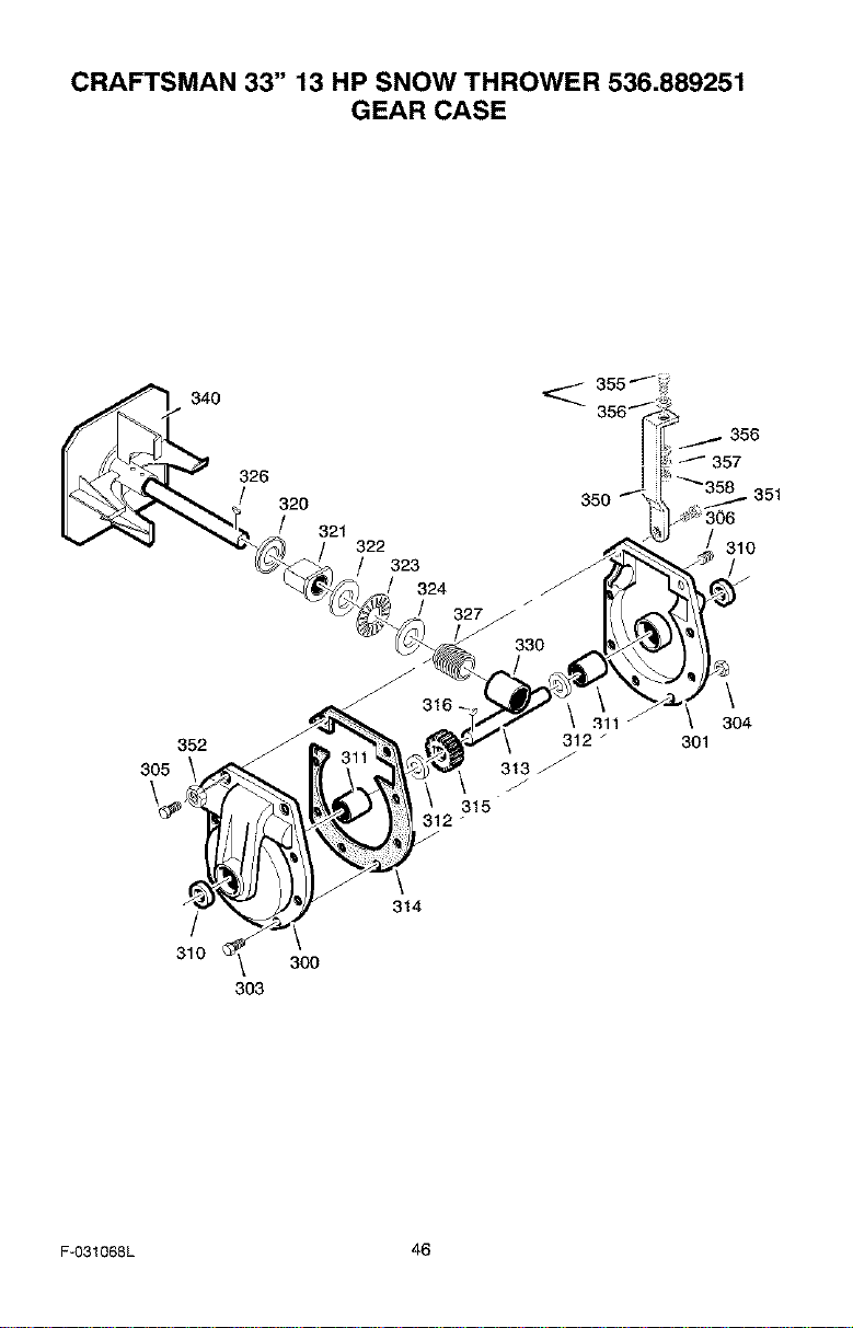
CRAFTSMAN 33" 13 HP SNOW THROWER 536.889251
GEAR CASE
340
326
320
321
322
323
324
305
352
312 _
313
315
312
304
301
314
/ \
310 _ 300
303
F-O31068L 46
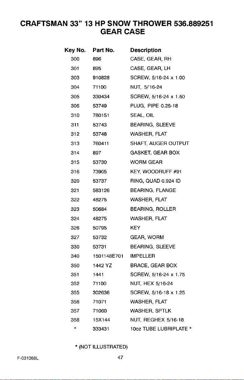
CRAFTSMAN 33" 13 HP SNOW THROWER 536.889251
GEAR CASE
Key No. Part No. Description
300 896 CASE, GEAR, RH
301 895 CASE, GEAR, LH
303 910828 SCREW, 5/16-24 x 1.00
304 71100 NUT, 5/'16-24
305 330434 SCREW, 5/16-24 x 1.50
306 53749 PLUG, PIPE 0.25-18
310 780151 SEAL, OIL
311 53743 BEARING, SLEEVE
312 53748 WASHER, FLAT
313 760411 SHAFT, AUGER OUTPUT
314 897 GASKET, GEAR BOX
315 53730 WORM GEAR
316 73905 KEY, WOODRUFF #91
320 53737 RING, QUAD 0.924 ID
321 583126 BEARING, FLANGE
322 48275 WASHER, FLAT
323 50684 BEARING, ROLLER
324 48275 WASHER, FLAT
326 50795 KEY
327 53732 GEAR, WORM
330 53731 BEARING, SLEEVE
340 1501148E701 IMPELLER
350 1442 YZ BRACE, GEAR BOX
351 1441 SCREW, 5/16-24 x 1.75
352 71100 NUT, HEX 5/16-24
355 302636 SCREW, 5/16-18 x 1.25
356 71071 WASHER, FLAT
357 71060 WASHER, SPTLK
358 15X144 NUT, REGHEX 5/16-18
333431 10oz TUBE LUBRIPLATE *
* (NOT ILLUSTRATED)
F-031068L 47
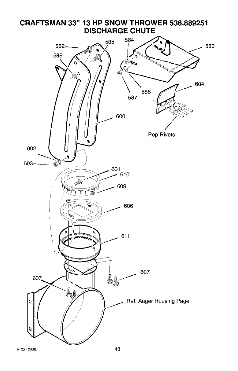
CRAFTSMAN 33" 13 HP SNOW THROWER 536.889251
DISCHARGE CHUTE
=86AAWI
602
603_ "
585 584
587
_. 600
601
610
580
604
Pop Rivets
609
I
606
611
6o7_
607
Ref. Auger Housing Page
F-031068L 48
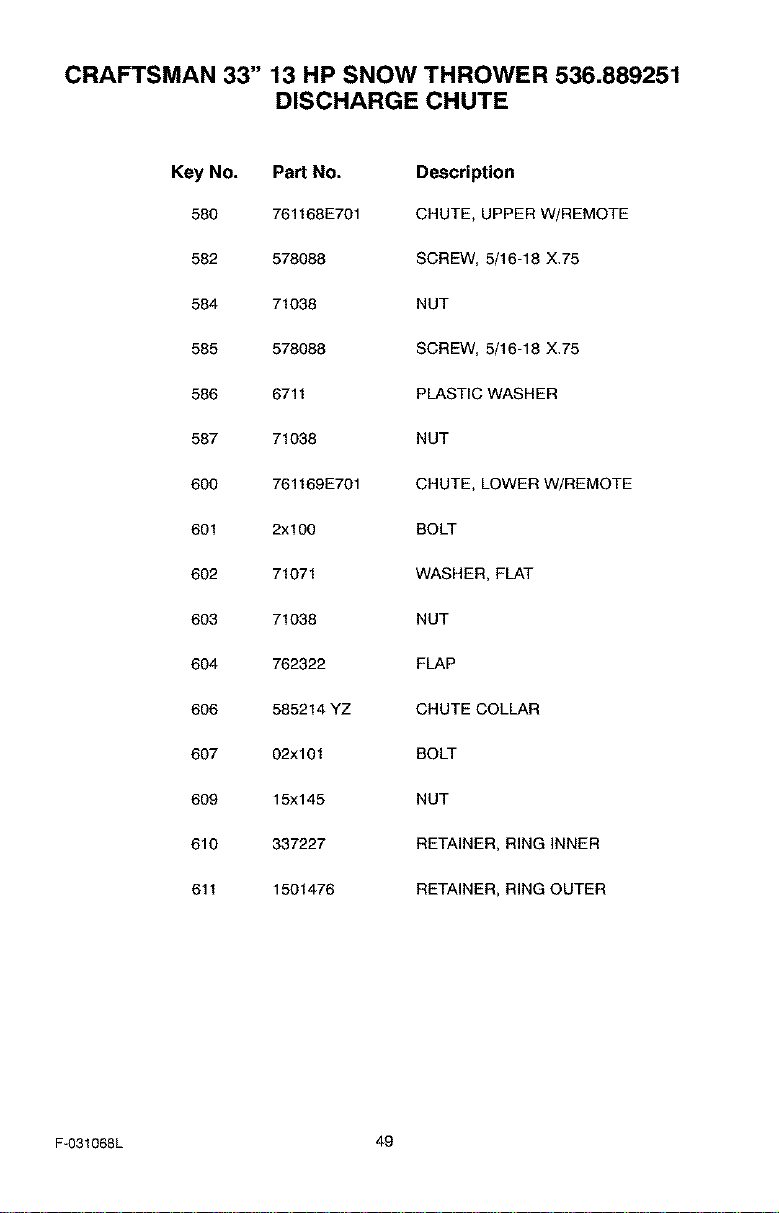
CRAFTSMAN 33" 13 HP SNOW THROWER 536.889251
DISCHARGE CHUTE
Key No. Part No. Description
580 761168E701 CHUTE, UPPER W/REMOTE
582 578088 SCREW, 5/16-18 X.75
584 71038 NUT
585 578088 SCREW, 5/16-18 X.75
586 6711 PLASTIC WASHER
587 71038 NUT
600 761169E701 CHUTE, LOWER W/REMOTE
601 2x100 BOLT
602 71071 WASHER, FLAT
603 71038 NUT
604 762322 FLAP
606 585214 YZ CHUTE COLLAR
607 02xl 01 BOLT
609 15x145 NUT
610 337227 RETAINER, RING INNER
611 1501476 RETAINER, RING OUTER
F-031068L 49
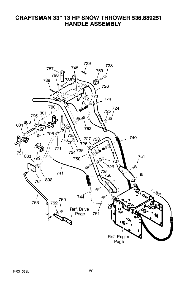
CRAFTSMAN 33" 13 HP SNOW THROWER 536.889251
HANDLE ASSEMBLY
739 723
787_ 745 759 /
798
739 _;_
\ 720
801 8
\
795
790
774
724
740
791
803 751
/
753
744
Page
751
Ref. Eng
Page
F-O31068L 50
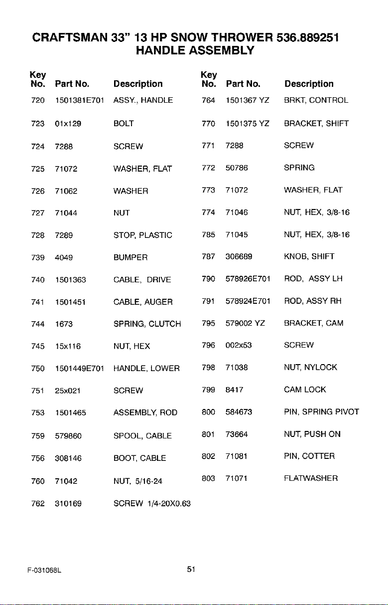
CRAFTSMAN 33" 13 HP SNOW THROWER 536.889251
HANDLE ASSEMBLY
Key Key
No. Part No. Description No. Part No. Description
720 1501381E701 ASSY., HANDLE 764 1501367YZ BRKT, CONTROL
723 01x129 BOLT 770 1501375 YZ BRACKET, SHIFT
724 7288 SCREW 771 7288 SCREW
725 71072 WASHER, FLAT 772 50786 SPRING
726 71062 WASHER 773 71072 WASHER, FLAT
727 71044 NUT 774 71046 NUT, HEX, 3/8-16
728 7289 STOP, PLASTIC 785 71045 NUT, HEX, 3/8-16
739 4049 BUMPER 787 306689 KNOB, SHIFT
740 1501363 CABLE, DRIVE 790 578926E701 ROD, ASSYLH
741 1501451 CABLE, AUGER 791 578924E701 ROD, ASSY RH
744 1673 SPRING, CLUTCH 795 579002 YZ BRACKET, CAM
745 15x116 NUT, HEX 796 002x53 SCREW
750 1501449E701 HANDLE, LOWER 798 71038 NUT, NYLOCK
751 25x021 SCREW 799 8417 CAM LOCK
753 1501465 ASSEMBLY, ROD 800 584673 PIN, SPRING PIVOT
759 579860 SPOOL, CABLE 801 73664 NUT, PUSH ON
756 308146 BOOT, CABLE 802 71081 PiN, COTTER
760 71042 NUT, 5/16-24 803 71071 FLATWASHER
762 310169 SCREW 1/4-20X0.63
F-031068L 51
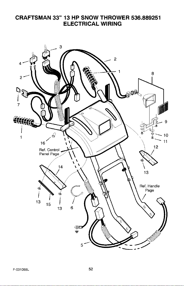
CRAFTSMAN 33" 13 HP SNOW THROWER 536.889251
ELECTRICAL WIRING
3
16
Ref.Control
Panel Page
13
6
Ref, Handle
Page
F-031068L 52
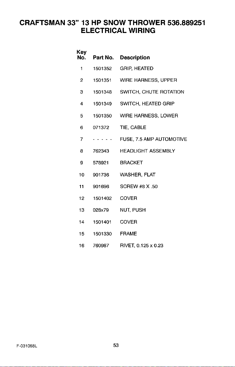
CRAFTSMAN 33" 13 HP SNOW THROWER 536.889251
ELECTRICAL WIRING
Key
No. Part No. Description
1 1501352
2 1501351
3 1501348
4 1501349
5 1501350
6 071372
7
8
9
10
11
12
13
14
15
16
762343
578921
901736
901696
1501402
028x79
1501401
1501330
760987
GRIP, HEATED
WIRE HARNESS, UPPER
SWITCH, CHUTE ROTATION
SWITCH, HEATED GRIP
WIRE HARNESS, LOWER
TIE, CABLE
FUSE, 7.5 AMP AUTOMOTIVE
HEADLIGHT ASSEMBLY
BRACKET
WASHER, FLAT
SCREW #8 X .50
COVER
NUT, PUSH
COVER
FRAME
RIVET, 0.125 x 0.23
F-031068L 53
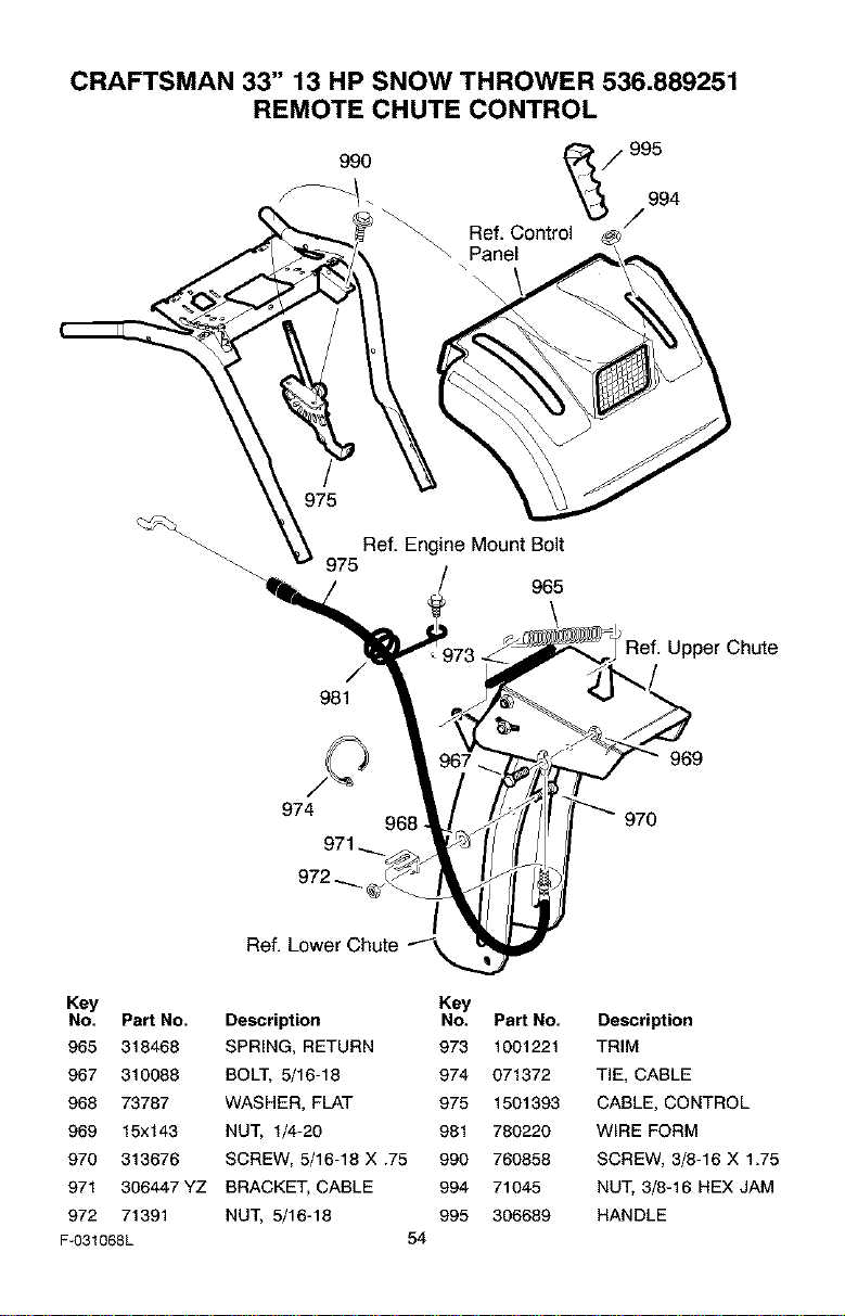
CRAFTSMAN 33" 13 HP SNOW THROWER 536.889251
REMOTE CHUTE CONTROL
990
I
_ / 965
\
Ref. Upper Chute
981
974
968
969
/
Ref. Lower Chute
Key
No. Part No. Description
965 318468 SPRING, RETURN
967 310088 BOLT, 5/16-18
968 73787 WASHER, FLAT
969 15x143 NUT, 1/4-20
970 313676 SCREW, 5/16-18 X .75
971 306447 YZ BRACKET, CABLE
972 71391 NUT, 5/16-18
F-O31068L 54
Key
No. Part No.
973 1001221
974 071372
975 1501393
981 780220
990 760858
994 71045
995 306689
Description
TRIM
TIE, CABLE
CABLE, CONTROL
WIRE FORM
SCREW, 3/8-16 X 1.75
NUT, 3/8-16 HEX JAM
HANDLE
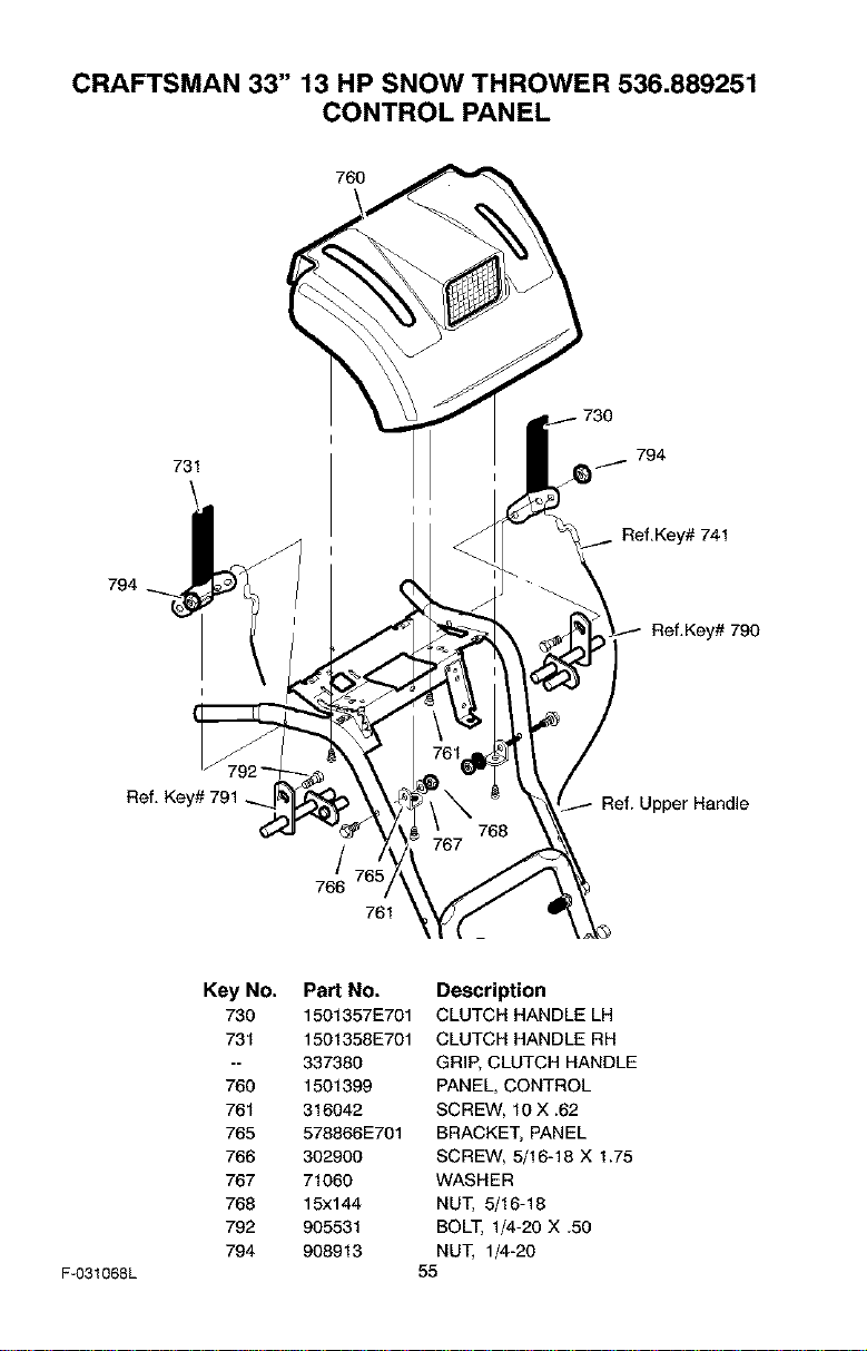
CRAFTSMAN 33" 13 HP SNOW THROWER 536.889251
CONTROL PANEL
760
794
731
Ref.Key#741
Ref.Key#790
Ref. Key# 791
Ipper Handle
766
761
F-031068L
Key No. Part No.
730 1501357E701
731 1501358E701
337380
760 1501399
761 316042
765 578866E701
766 302900
767 71060
768 15x144
792 905531
794 908913
Description
CLUTCH HANDLE LH
CLUTCH HANDLE RH
GRI_ CLUTCH HANDLE
PANEL, CONTROL
SCREW, 10 X.62
BRACKE_ PANEL
SCREW, 5/16-18 X 1.75
WASHER
NU_ _16-18
BOLT, I_-20 X .50
NU_ 1_-20
55
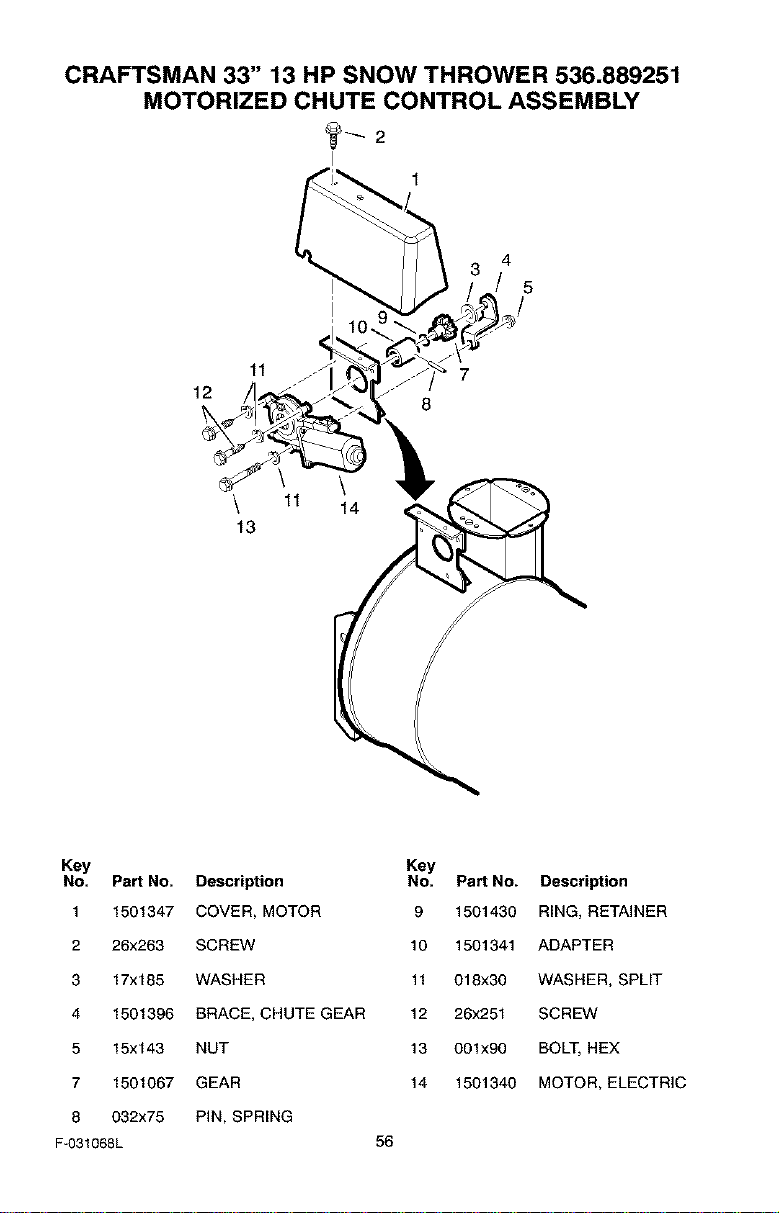
CRAFTSMAN 33" 13 HP SNOW THROWER 536.889251
MOTORIZED CHUTE CONTROL ASSEMBLY
4
5
11 7
12
8
\ 11 14
13
Key Key
No. Part No. Description No. Part No. Description
1 1501347 COVER, MOTOR 9 1501430 RING, RETAINER
2 26x263 SCREW 10 1501341 ADAPTER
3 17x185 WASHER 11 018x30 WASHER, SPLIT
4 1501396 BRACE, CHUTE GEAR 12 26x251 SCREW
5 15x143 NUT 13 001x90 BOLT, HEX
7 1501067 GEAR 14 1501340 MOTOR, ELECTRIC
8 032x75 PIN, SPRING
F-O31068L 56

CRAFTSMAN 33" 13 HP SNOW THROWER 536.889251
DRIFT CUTTER ASSEMBLY
RIGHT SIDE OF
Key No. Part No. Description
280 762348E701 DRIFT CUTI-ER
281 340720 BOLT
282 12021 WASHER
283 711604 WlNGNUT
284 11261 STOP, PLASTIC
F-031068L 57
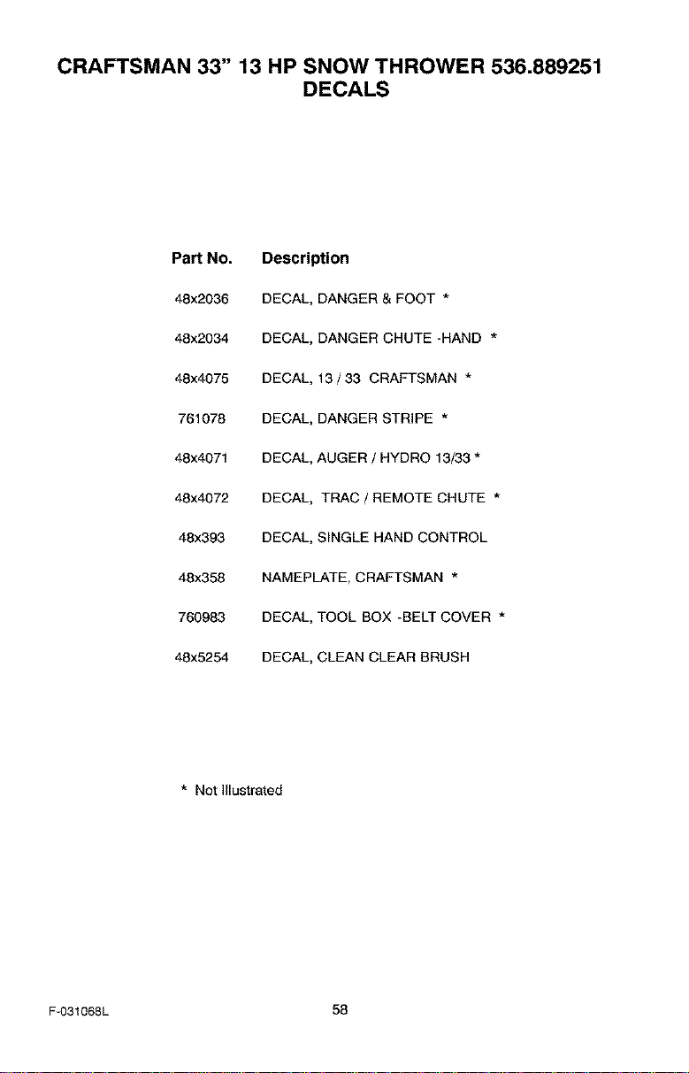
CRAFTSMAN 33" 13 HP SNOW THROWER 536.889251
DECALS
PaN No.
48x2036
48x2034
48x4075
761078
48x4871
48x4072
48x393
48x358
760988
48x5254
Description
DECAL, DANGER & FOOT *
DECAL, DANGER CHUTE -HAND *
DECAL, 13/33 CRAFTSMAN *
DECAL, DANGER STRIPE *
DECAL, AUGER / HYDRO 13/33 *
DECAL, TRAC / REMOTE CHUTE *
DECAL, SINGLE HAND CONTROL
NAMEPLATE, CRAFTSMAN *
DECAL, TOOL BOX -BELT COVER *
DECAL, CLEAN CLEAR BRUSH
* Not Illustrated
F-031068L 58
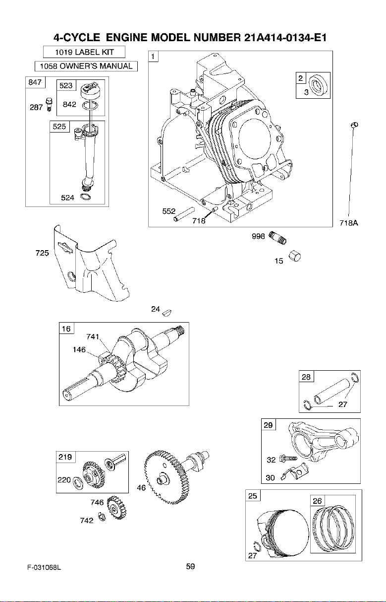
4-CYCLE ENGINE MODEL NUMBER 21A414-0134-E1
1019 LABEL KIT
I 1058 OWNER'S MANUAL I
287 I
524
725
718A
24
741
\
Fu031068L 59
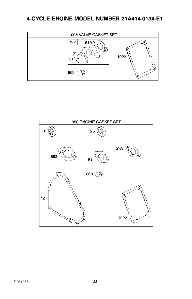
4-CYCLE ENGINE MODEL NUMBER 21A414-0134-E1
1095 VALVE GASKET SET
868
358 ENGINE GASKET SET
20
51A
51
868 _)
1022
F-031068L 60
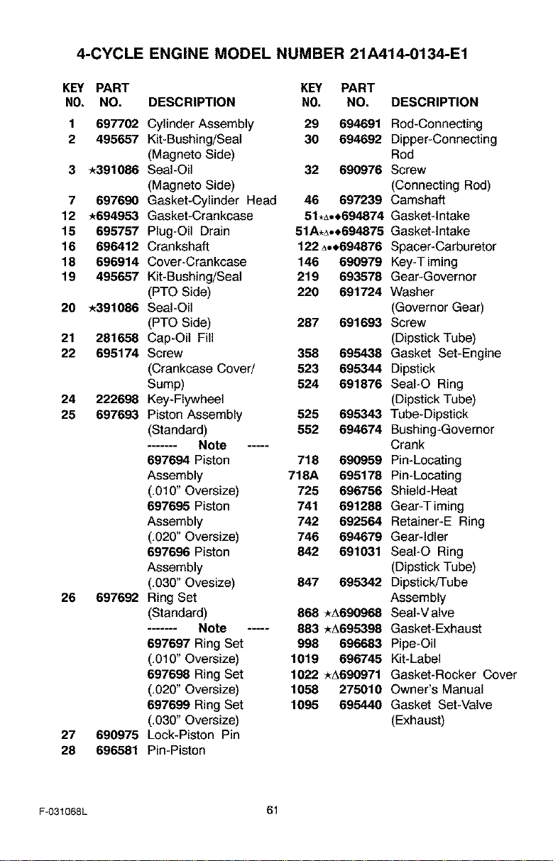
4-CYCLE ENGINE MODEL NUMBER 21A414-0134-E1
KEY PART
NO. NO.
KEY PART
DESCRIPTION N0. NO. DESCRIPTION
1 697702 Cylinder Assembly 29 694691 Rod-Connecting
2 495657 Kit-Bushing/Seal 30 694692 Dipper-Connecting
(Magneto Side) Rod
3 _391086 Seal-Oil 32 690976 Screw
(Magneto Side) (Connecting Rod)
7 697690 Gasket-Cylinder Head 46 697239 Camshaft
12 -*694953 Gasket-Crankcase 51,A,,694874 Gasket-Intake
16 696767 Plug-Oil Drain 51A,A,,694875 Gasket-Intake
16 696412 Crankshaft 122A,,694876 Spacer-Carburetor
16 696914 Cover-Crankcase 146 690979 Key-Timing
19 495657 Kit-Bushing/Seal 219 693578 Gear-Governor
(PTO Side) 220 691724 Washer
20 _391086 Seal-Oil (Governor Gear)
(PTO Side) 287 691693 Screw
21 281658 Cap-Oil Fill (Dipstick Tube)
22 695174 Screw 356 695438 Gasket Set-Engine
(Crankcase Coved 523 695344 Dipstick
Sump) 524 691876 SeaI-O Ring
24 222698 Key-Flywheel (Dipstick Tube)
26 697693 Piston Assembly 525 695343 Tube-Dipstick
(Standard) 552 694674 Bushing-Governor
....... Note ..... Crank
697694 Piston 716 690969 Pin-Locating
Assembly 718A 695178 Pin-Locating
(.010" Oversize) 725 696766 Shield-Heat
697695 Piston 741 691288 Gear-Timing
Assembly 742 692564 Retainer-E Ring
(.020" Oversize) 746 694679 Gear-Idler
697696 Piston 842 691031 SeaI-O Ring
Assembly (Dipstick Tube)
(.030" Ovesize) 847 695342 Dipstick/Tube
26 697692 Ring Set Assembly
(Standard) 868 *A690968 Seal-Valve
....... Note ..... 883 *A695398 Gasket-Exhaust
697697 Ring Set 998 696683 Pipe-Oil
(.010" Oversize) 1019 696746 Kit-Label
697698 Ring Set 1022 *A690971 Gasket-Rocker Cover
(.020" Oversize) 1058 275010 Owner's Manual
697699 Ring Set 1095 695440 Gasket Set-Valve
(.030" Oversize) (Exhaust)
27 690975 Lock-Piston Pin
28 696581 Pin-Piston
F-031068L 61
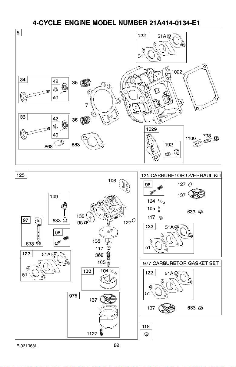
4-CYCLE ENGINE MODEL NUMBER 21A414-0134-E1
866_
108
633 @ 135
117 _
369 _
105
_ 137_
121 CARBURETOR OVERHAUL KN
127 0
137
1o4
105
633 @
117
977 CARBURETOR GASKET SET
51A_
137 _ 633@
1127
F-O31068L 62
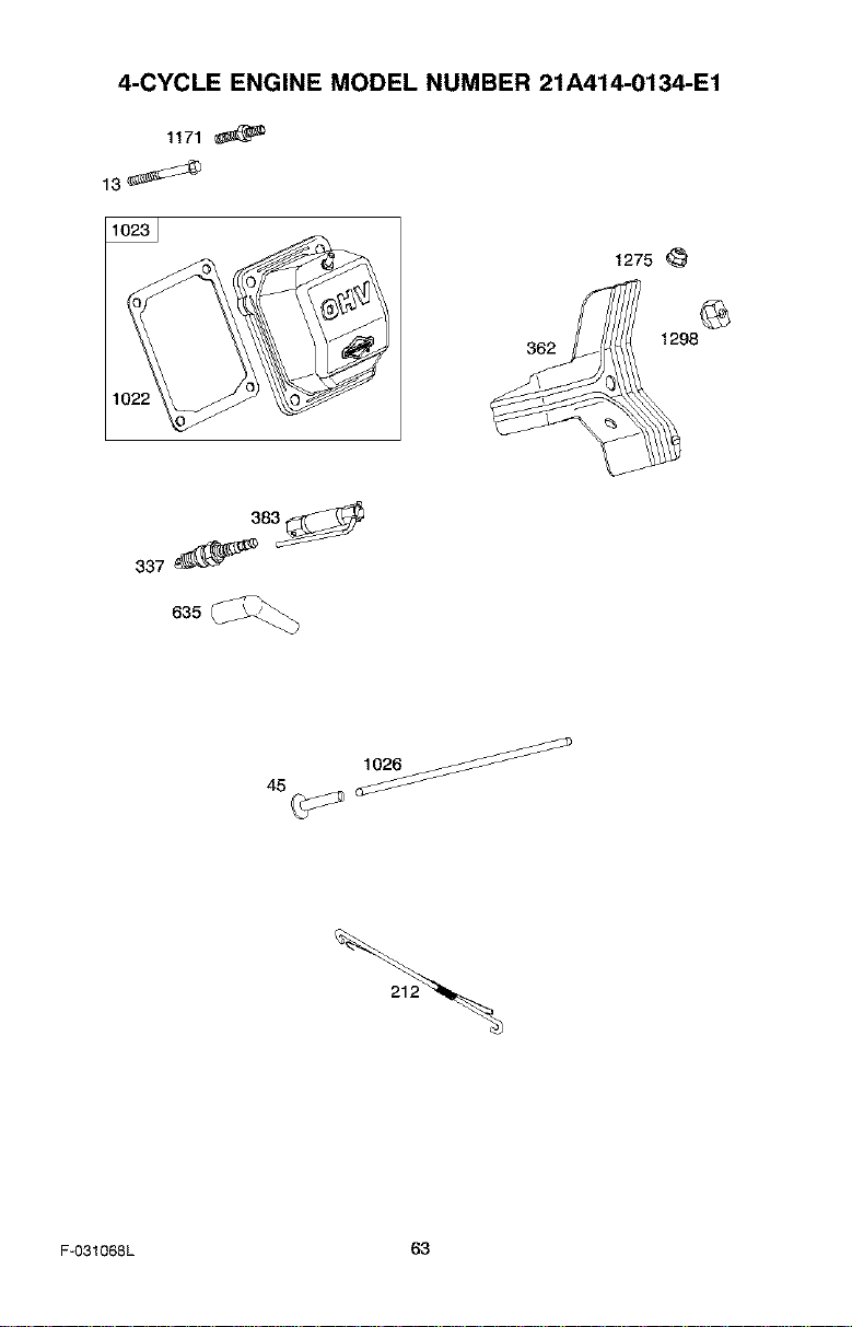
4-CYCLE ENGINE MODEL NUMBER 21A414-0134-E1
1171
1(
362
1275
1298
3_3_
337
635
F-O31068L 63
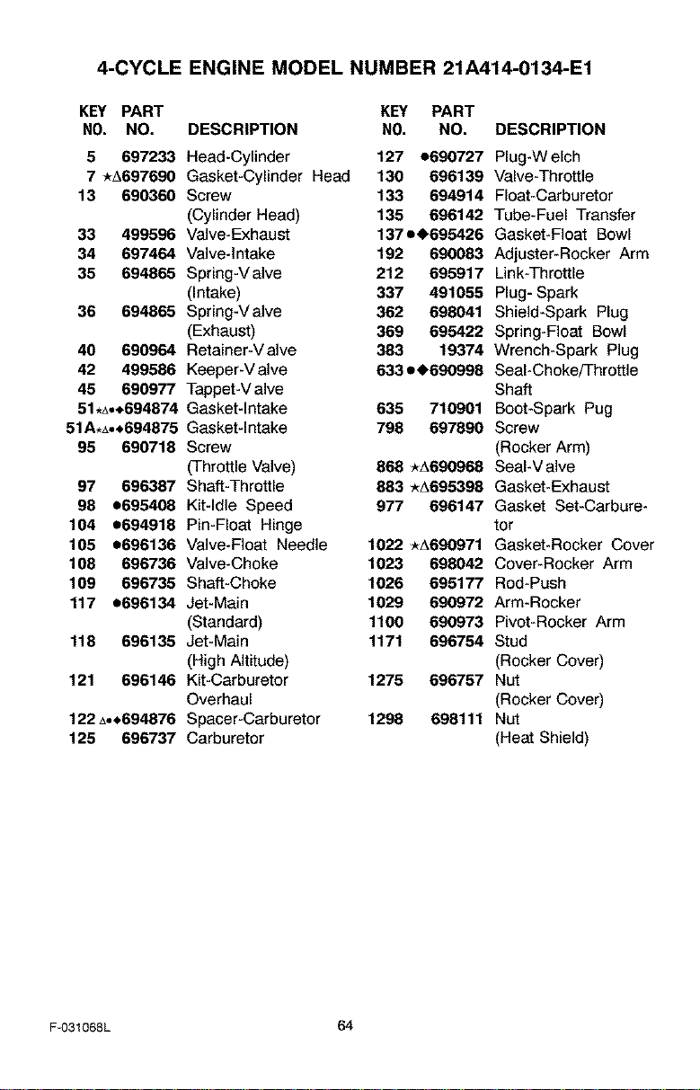
4-CYCLE ENGINE MODEL NUMBER 21A414-0134-E1
KEY PART KEY PART
NO. NO. DESCRIPTION NO. NO. DESCRIPTION
5 697233 Head-Cylinder 127 e690727 Plug-Welch
7 *A697690 Gasket-Cylinder Head 130 696139 Valve-Throttle
13 690360 Screw 133 694914 Float-Carburetor
(Cylinder Head) 135 696142 Tube-Fuel Transfer
33 499596 Valve-Exhaust 137e_695426 Gasket-Float Bowl
34 697464 Valve-Intake 192 690083 Adjuster-Rocker Arm
35 694865 Spring-Valve 212 695917 Link-Throttle
(Intake) 337 491055 Plug- Spark
36 694865 Spring-Valve 362 698041 Shield-Spark Plug
(Exhaust) 369 695422 Spring-Float Bowl
40 690964 Retainer-Valve 383 19374 Wrench-Spark Plug
42 499586 Keeper-V alve 633 e_690998 Seal-Choke/Throttle
45 690977 Tappet-Valve Shaft
51.A.,694874 Gasket-Intake 635 710901 Boot-Spark Pug
51A.A°*694875 Gasket-Intake 798 697890 Screw
95 690718 Screw (Rocker Arm)
(Throttle Valve) 888 *A690988 SeaI-V alve
97 696387 Shaft-Throttle 883 _A695398 Gasket-Exhaust
98 e695408 Kit-Idle Speed 977 696147 Gasket Set-Carbure-
104 e694918 Pin-Float Hinge tor
105 e696136 Valve-Float Needle 1022 _A690971 Gasket-Rocker Cover
108 696736 Valve-Choke 1023 698042 Cover-Rocker Arm
109 696735 Shaft-Choke 1026 695177 Rod-Push
117 e696134 Jet-Main 1029 690972 Arm-Rocker
(Standard) 1100 690973 Pivot-Rocker Arm
118 696135 Jet-Main 1171 696754 Stud
(High Altitude) (Rocker Cover)
121 696146 Kit-Carburetor 1275 696757 Nut
Overhaul (Rocker Cover)
122A°_694876 Spacer-Carburetor 1298 698111 Nut
125 696737 Carburetor (Heat Shield)
F-031068L 64
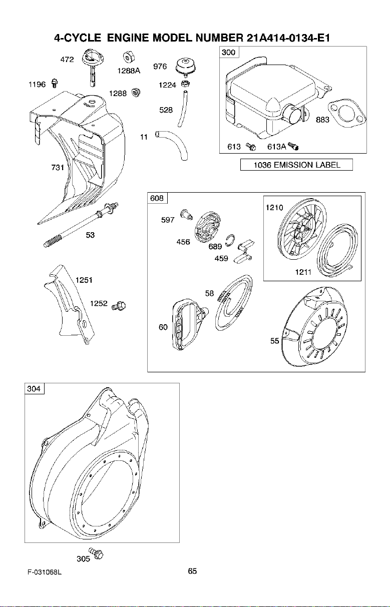
1196 '_
4-CYCLE ENGINE MODEL NUMBER 21A414-0134-E1
731
472_
1288A
1288
976
1224
528
613 _ 613A_
1036 EMISSION LABEL
53
597_(_
456 684959_b
60
1211
F-031068L 65
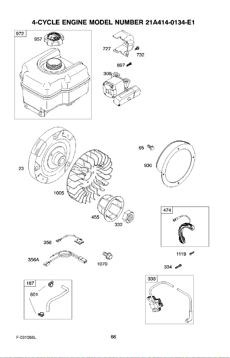
4-CYCLE ENGINE MODEL NUMBER 21A414-0134-E1
957
727
697
732
23
1005
455
332
1070
1119
334
F-O31068L 66
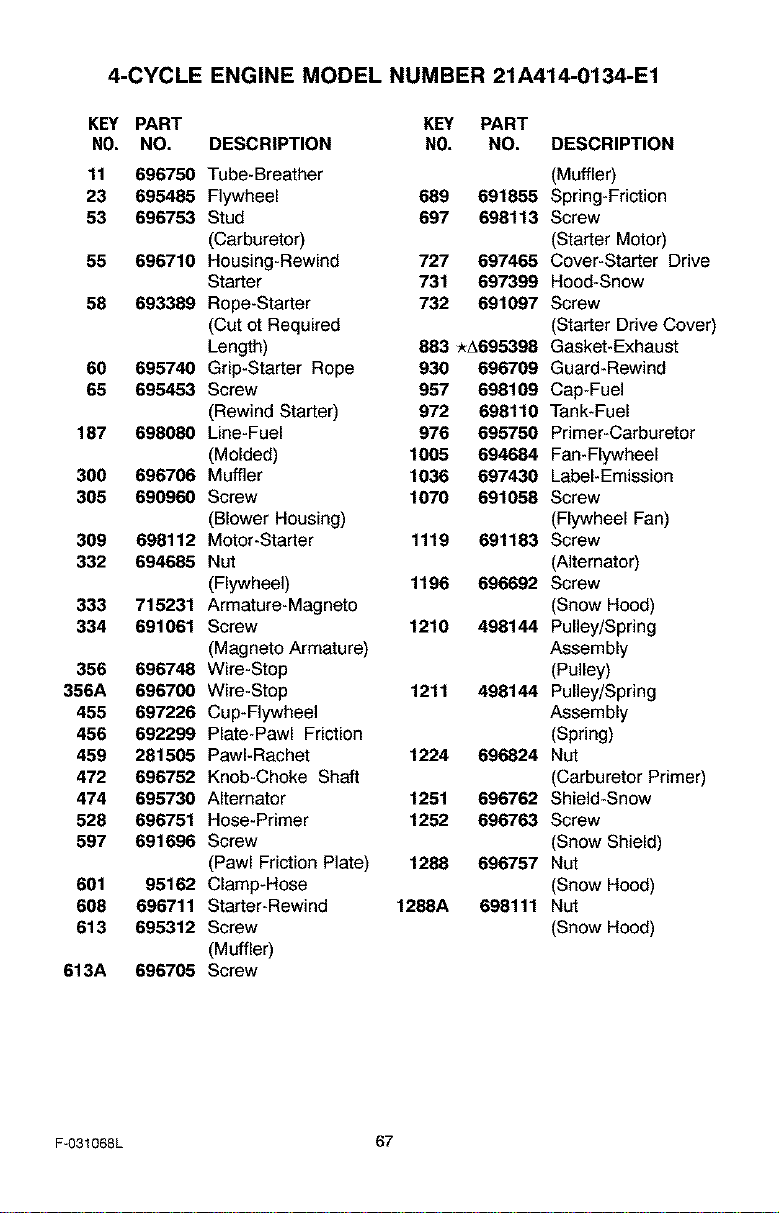
4-CYCLE ENGINE MODEL NUMBER 21A414-0134-E1
KEY PART KEY PART
NO. NO. DESCRIPTION NO. NO. DESCRIPTION
11 696750 Tube-Breather (Muffler)
23 695485 Flywheel 689 691855 Spring-Friction
53 696753 Stud 697 698113 Screw
(Carburetor) (Starter Motor)
55 696710 Housing-Rewind 727 697465 Cover-Starter Drive
Starter 731 697399 Hood-Snow
58 693389 Rope-Starter 732 691097 Screw
(Cut et Required (Starter Drive Cover)
Length) 883 _A695398 Gasket-Exhaust
60 695740 Grip-Starter Rope 930 696709 Guard-Rewind
65 695453 Screw 957 698109 Cap-Fuel
(Rewind Starter) 972 698110 Tank-Fuel
187 698080 Line-Fuel 976 695750 Primer-Carburetor
(Molded) 1005 694684 Fan-Flywheel
300 696706 Muffler 1036 697430 Label-Emission
305 690960 Screw 1070 691058 Screw
(Blower Housing) (Flywheel Fan)
309 698112 Metor-Starter 1119 691183 Screw
332 694685 Nut (Alternator)
(Flywheel) 1196 696692 Screw
333 715231 Armature-Magneto (Snow Hood)
334 691061 Screw 1210 498144 Pulley/Spring
(Magneto Armature) Assembly
356 696748 Wire-Stop (Pulley)
356A 696700 Wire-Stop 1211 498144 Pulley/Spring
455 697226 Cup-Flywheel Assembly
456 692299 Plate-Pawl Friction (Spring)
459 281505 PawI-Rachet 1224 696824 Nut
472 696752 Knob-Choke Shaft (Carburetor Primer)
474 695730 Alternator 1251 696762 Shield-Snow
528 696751 Hose-Primer 1252 696763 Screw
597 691696 Screw (Snow Shield)
(Pawl Friction Plate) 1288 696757 Nut
601 95162 Clamp-Hose (Snow Hood)
608 696711 Starter-Rewind 1288A 698111 Nut
613 695312 Screw (Snow Hood)
(Muffler)
613A 696705 Screw
F-031068L 67
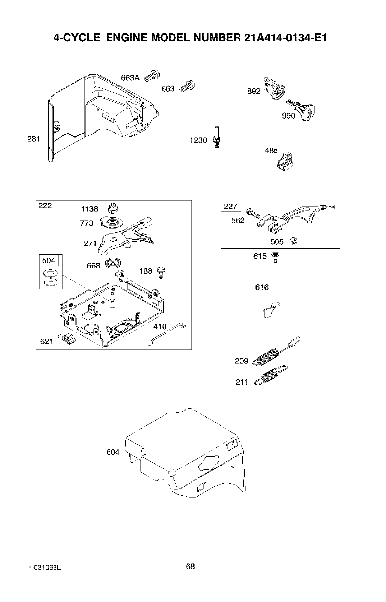
4-CYCLE ENGINE MODEL NUMBER 21A414-0134-E1
281
683_ 892_o_
1230
485_
222_ 1138
271 _
_2__
505 @
615
2ooJ
211 S
604
F-O31068L 68
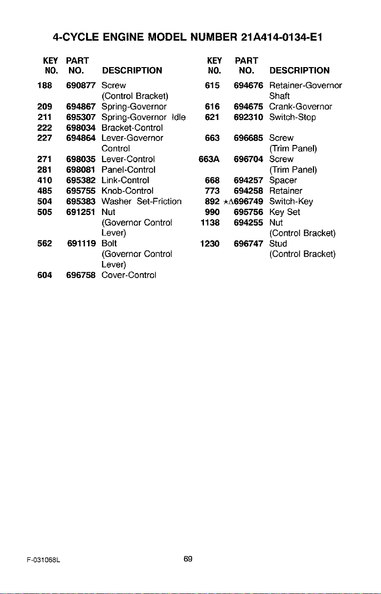
4-CYCLE
KEY PART
NO. NO.
188 690877
209 694867
211 695307
222 698034
227 694864
271 698035
281 698081
410 695382
485 695755
504 695383
505 691251
562 691119
604 696758
ENGINE MODEL NUMBER 21A414-0134-E1
KEY PART
DESCRIPTION NO. NO. DESCRIPTION
Screw 615 694676 Retainer-Governor
(Control Bracket) Shaft
Spring-Governor 616 694675 Crank-Governor
Spring-Governor Idle 621 692310 Switch-Stop
Bracket-Control
Lever-Governor 663 696685 Screw
Control (Trim Panel)
Lever-Control 663A 696704 Screw
Panel-Control (Trim Panel)
Link-Control 668 694257 Spacer
Knob-Control 773 694256 Retainer
Washer Set-Friction 892 _A696749 Switch-Key
Nut 990 695756 Key Set
(Governor Control 1138 694255 Nut
Lever) (Control Bracket)
Bolt 1230 696747 Stud
(Governor Control (Control Bracket)
Lever)
Cover-Control
F-031068L 69

[_o] _I 1:1_IIm]_o]
PIEZASDEREPUESTO ............ 39
PIEZASDEREPUESTO- MOTOR .... 59
GARANTIA ..................... 70
REGLASDESEGURIDAD .......... 70
SIMBOLOSINTERNACIONALES..... 73
ENSAMBLAJE................... 75
OPERACI(_N .................... 82
MANTENIMIENTO................ 89
SERVICIOY AJUSTES............. 92
ALMACENAMIENTO............... 101
TABLADELOC_UZACI(_NY
REPARACIONDEAVERIAS ..... 102
PEDIDODEPIEZAS/SERVICIO....... 108
[@-! ItiY-I
GARANTiA UMITADA DE DOS AI_IOS PARA EL QUITANIEVES CRAFTSMAN
Durante dos argosa par'Jrde la fecha de compra, siempre que a este quitanieves Craftsman se le
d6 mantenimiento, lubricaci6n y afinamiento de acuerdo con las instrucciones de operaci6n y man*
tenimiento presentadas en el manual del usuario, Sears reparar&, sin cargo alguno, cualquier defec*
to en material y mano de obra.
Si este quitanieves Craftsman es usado con propSsitos comerciales o de arrendamiento, esta ga*
rantia ser& v&lida solamente pot 90 dias a partir de la fecha de compra.
Esta garantia no cubre Io siguiente:
Elementos de dosgaste normal, tales como bujias, correas detransmisi6n y pasadores de segu-
ridad.
Reparaciones necesarias debido al abuso o negligencia del operador, incluyendo varillas dobla*
dos y otras reparaciones necesarias gor falta del mantenimiento a la unidad segL_nIo recomem
dado on las instrucciones contenidas en el manual del propietario.
EL SERVICIO DE GARANTiA SE PUEDE OBTENER LLEVANDO EL QUITANIEVES AL CEN-
TRO DE SERVICIO SEARS MAS CERCANO EN LOS ESTADOS UNIDOS. ESTA GARANTiA ES
VALIDA S_LO CUANDO ESTE PRODUCTO ES USADO EN LOS ESTADOS UNIDOS.
Esta garantia le otorga derechos legales especi§cos, y asimismo es posibleque tenga otros dere-
chos los cuales varian de un estado a otto.
Soars, Roebuck and Co., D817WA, Hoffman Estates, IL 60179
Preste atenci6n a esto simbolo, le indica precauciones do seguridad importantos. Sig-
nifica--iiiA TENCION!!! iii ESTE ALERTA!!! Se trata de su seguridad.
Las emanaciones de escape producidas pot este
motor y ciertos componentes de esta mbquina con-
tienen qulmicos reconocidos por el Estado de Cali-
fornia como carcinbgenos, tambibn pueden produ-
cir defectos en los reci_n nacidos o causar otros da*
r_osal sistema reproductivo.
Los bornes, terminales y accesorios relacionados
con la baterla contienen plomo y compuestos del
plomo, adembs de sustancias qulmicas que el Esta-
do de California reconoce que estos compuestos
pueden causar cancer y defectos como carcinbge*
has, adembs estas sustancias pueden producir da-
r_oscong_nitos, a los bebes y adem_s de otros da*
r_osal sistema reproductivo humano. DEBE LAVAR-
SE MUY BIEN LAS MANOS DESPUES DE MANIPU-
LAR ESTOS COMPONENTES.
F-031068L 70
4_ ADVERTENCIA:
Siempre desconecte
el cable de la bujia y
colbquelo alejado de bsta
para prevenir un arranque
accidental durante la prepe-
racion mantenimiento o al-
macenamiento del quitanie-
ves.
IMPORTANTE: Para prevenir
Iosiones, las normas de seguri-
dad exigen controles en ]aunidad
que s61o puedan ser manojados
en presencia del operador. Su
quitanievos est,, equipado con
dichos controles. Por ning_n mo-
tive intente pasar pot alto la fun-
ci6n de] control en presoncia del
oporador.
CAPAClTACIbN
1. Lea can atenci6n las instrucciones en el
manual de aperaci6n y servicio. Familiad-
cese completamente con los controles y
el use apropiado del quitanieves. Apren-
da a detener el quitanieves y a desen-
ganchar rapidemente las contrales.
2. Nunca permita a nifios operar el quite-
nieves. Nunca permita que adultes epe-
ren el quitanieves sin la instrucci6n
aprapiada.
3. Mantenga el Area libre de personas, es-
pecialmente niSes pequer_os y mascatas.
4. Tenga mucho cuidado pare evitar resba-
lanes o ca{das, especialmente cuanda
est6 retrecediendo.
PREPARACION
1. Inspeccione campletemente el Area don-
de se usara el quitanieves y retire tadas
las esteras, trinees, tableros, cables, y
atras ebjetos extrafios.
2. Desengenche todes las embragues antes
de hacer arrancar el motor.
3. Na apere el quitanieves sin vestir pren-
des de inviemo adecuadas pare trabajar
ala intemperie. Vista calzada que le d_
buena tracci6n sabre superficies resbalo-
sas.
4. Maneje el combustible con cuidado; _ste
es altamente inflamable.
(a) Use un contenedar aprabado pare
combustible.
(b) Nunca quite la tape del tanque de
combustible ni afieda combustible a
un motar ell marcba a 8.un motor ca-
[iente.
(c) Llene el tanque de combustible al ai-
re libra y con mucha cuidada. Nunca
[lena el tanque en un recinta cerrado.
(d) Vuelva a colacar le tapa del tanque
de combustible de manera segura, y
[impie el combustible derramado.
(e) Nunca almacene combustible a el
quitanieves can combustible en el
tanque dentro de un edificio donde
los vapores pudiesen alcanzar algu-
na llama abierta o chispas.
(f) Verifique que el quitanieves tenga
suficiente combustible antes de ceda
uso, y deje un espacio adicional en el
tanque puesto que el calor del motor
F-031068L 71
y/o del sal hace que el combustible
se expande.
5. Para todos los quitanieves con motores
de arranque el6ctrico, use cables de ex-
tensi6n con certificaci6n CSA!UL. Use
solamente tomacorrientes que hayan si-
do instalados de acuerdo con los regla-
mentos de inspecci6n locales.
6. JamAs intente efectuar ningt_n aiuste
mientras el motor se encuentra en mar-
cha (excepto cuando el fabricante Io re-
comiende asi especificamente).
7. Permita que el motor y el quitanieves se
ajusten alas temperaturas exteriores an-
tes de comenzar a despejer la nieve.
8. Siempre use gafas de seguridad o pro-
tectores para los ojos durante la opera-
ciAn o mientras efectQa algQn ajuste o
reparaci6n a la unidad, pare proteger sus
ojos de objetos extrafios que pudiesen
set lanzados por el quitanieves.
OPERACI_N
1. Na opere este quitanieves siesta taman-
da medicines qua puedan causer samno-
lencia o afectar su habilidad pare operar
el quitanieves.
2. No use el quitenieves si por motives
emocianales o f{sicas sele dfficulta ma-
nejarla de forma segura.
3. No calaque las manes a los pies cerca a
debaja de piezas en movimiento. Man-
t6ngase en todo momento a buena dis-
tancia de la abertura del tube de
descarga.
4. Tenga mucho cuidado al operar el quita-
nieves en o a tray,s de entradas de au-
tos, senderas o caminos de grava.
Mant_ngase alerta de peligros ocultos o
trafico.
5.. Si golpea un objeto extrar_o, pare el mo-
tor, desconecte el cable de la buj{a, ins-
peccione metJculasamente el quitanieves
por si hubiera alg_n daSo, y rep&relo an-
tes de arrancar el motor y operar el quita-
nieves nuevamente.
6. Si el quitanieves camienza a vibrar de
manera excesiva, pare el motor y revise-
Io inmediatamente para encontrar la cau-
se. Generalmente, la vibraci6n es una
advertencia de algt3n problema.
7. Pare el motor cuando deje la posiciAn de
operaci6n, antes de desobstruir el aloja-
miento de la barrena/propulsor o el tubo
de descarga, y cuando efect_e cualquier
reparaci6n, ajuste a inspecci6n.
8. Cuando limpie, repare o inspeccione el
quitanieves, asegt3rese de que la barre-
na/propulsorytodaslaspartesm6viles
seencuentrendetenidas,yquetodoslos
controlesest6ndesenganchados.Desco-
necteelcabledelabujiaymantAngalo
alejadodelabujiaparaevitarunarran-
queaccidental.
9. Tometodaslasprecaucionesposiblesal
dejarelquitanievesdesatendido.Desen-
ganchelabarrena/propulsor,pareel mo-
tor y retire ]a Ilave.
10. No haga arrancar el motor en recintos
cerrados, excepto para arrancar y para
transportar el quitanieves hacia adentro o
hacia afuera del recinto. Abra las puertas
que dan al exterior; los vapores de esca-
pe son peligrosos (contienen MONOXl-
DO DE CARBONO, un GAS INODORO y
LETAL).
11. No use el quitanieves para limpiar Areas
de terreno inclinadas (cuestas, pendien-
tes). Tenga mucho cuidado cuando cam-
bie de direcci6n. No intente limpiar
pendientes muy pronunciadas.
12. Nunca opere el quitanieves sin que los
resguardos, placas u otros dispositivos
de seguridad se encuentren en su lugar.
13. Nunca opere el quitanieves cerca de es-
caparates de vidrio, automAviles, vidde-
ras, sitios de carga/descarga, y similares,
sin el ajuste apropiado del Angulo de des-
carga de la nieve. Mantenga a los niSos y
las mascotas alejados del Area que estA
despejando.
14. No sobrecargue la capacidad del quita-
nieves al intentar limpiar la nieve a una
velocidad demasiado rapida.
15. Nunca opere el quitanieves a altas velooi-
dades de transporte sobre superficies
resbalosas. Mire hacia atrAs y tenga cui-
dado al retroceder.
16. Nunca descargue directamente hacia es-
pectadores ni permita a nadie frente al
quitanieves.
17. Desenganche la fuerza motriz de la ba-
rrenajpropulsor cuando el quitanieves
sea trasportado o no estA en uso.
18. Utilice t3nicamente aditamentos y acceso-
dos aprobados por el fabricante del quita-
nieves (tales come cadenas para las
ruedas, juegos de arranque el_ctdco,
etc.).
19. Nunca opere el quitanieves sin tener bue-
na visibilidad o iluminaci6n. AsegSrese
siempre que tiene buena estabilidad, y
sujete con firmeza el mango. Camine;
nunca corra,
20. No trate de alcanzar Areas diffciles. Man-
tenga la estabilidad y el balance en todo
momenta.
21. No trate de usar el quitanieves para lim-
piar techos.
MANTENIMIENTO Y
ALMACENAMIENTO
1. Revise los pemos con frecuencia para
asegurar que estAn bien apretados y que
el quitanieves est_ en condiciones segu-
ras de funcionamiento.
2. Nunca guarde el quitanieves con com-
bustible en el tanque dentro de un recinto
donde hubieran fuentes de ignici6n tales
como calentadores de agua y est_as,
secadoras de ropa, y similares. Permita
que el motor se enfrie antes de guardar
el quitanieves en cualquier recinto.
3. Si va a almacenar el quitanieves par un
periodo prolongado, siempre consulte las
instrucciones del manual del operador
donde encontrara consejos importantes.
4. Mantenga o reemplace las etiquetas de
seguridad e instrucciones, segSn sea ne-
cesario.
5. Mantenga el quitanieves en marcha unos
cuantos minutos despuAs de despejar la
nieve, para evitar que se congele la ba-
rrena!propulsor.
,_ ADVERTENCIA: Este quitanieves
es para use en aceras, entradas
de auto y otras superficies de te-
rreno planas. Se debe tenet cuidado al
usar el quitanieves en superficies inclina-
das. NO USE EL QUITANIEVES EN SU-
PERFICIES SOBRE EL NIVEL DEL SUELO
tales come techos de residencias, de ga-
rajes, perches u otras estructuras o cons-
trucciones similares.
F-031068L 72
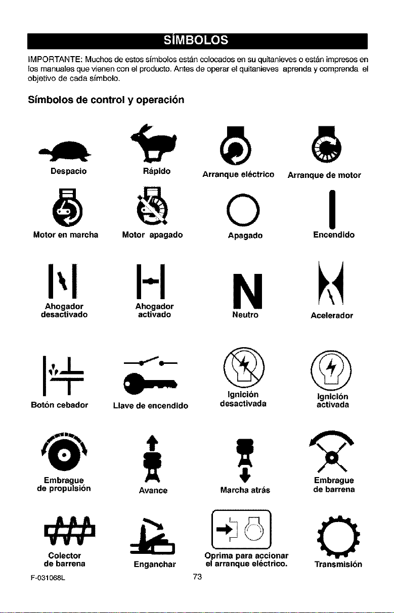
_,_o_oI,,_
IMPORTANTE: Muchos de estos simbolos es_an colocados en su qu_tanieves o estan impresos en
los manuales que vienen con el producto. Antes de operar el quitanieves aprenda y comprenda el
objetivo de cada simbolo,
Simbolos de control y operaci6n
Despacio Rapido Arranque el_ctrico
@ o
Arranque de motor
I
Motor en marcha Motor apagado Apagado Encendido
H N k4
Ahogador Ahogador
desactivado activado Neutro Acelerador
Boton cebador
Llave de encendido
@ @
Ignicibn Ignicibn
desactivada activada
Embrague
de propulsibn
Colector
de barrena
F-031068L
T 2
Avance Marcha atrbs de barrena
Enganchar Transmision
o
el arranque el_ctrico.
73
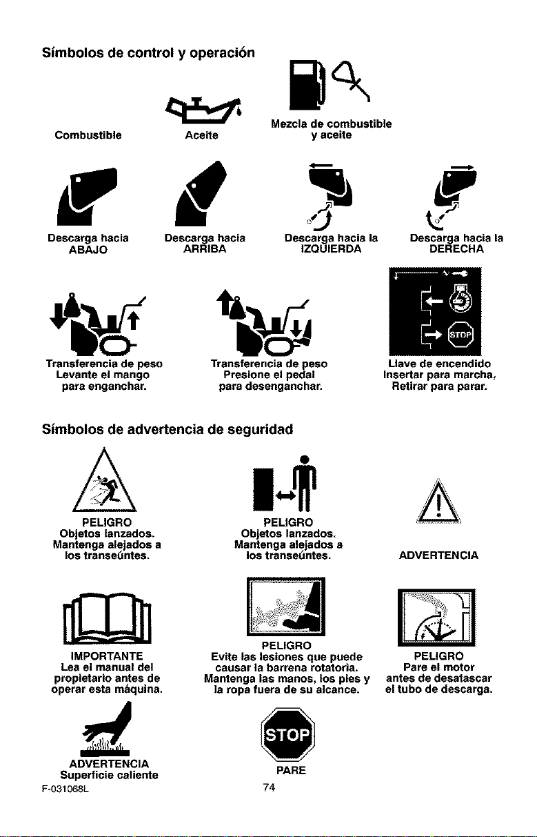
Simbolos de control y operacibn
Mezcla de combustible
Combustible Aceite y aceite
f d
Descarga hacia Descarga hacia Descarga hacia la Descarga hacia la
ABAJO ARRIBA IZQUIERDA DERECHA
Transferencia de peso Transferencia de peso Uave de encendido
Levante el mango Presione el pedal Insertar pars marcha,
pars enganchar, para desenganchar. Retirar para parar.
Simbolos de advertencia de seguridad
PELIGRO
Objetos lanzados.
Mantenga alejados a
los transet_ntes.
$
PEUGRO
Objetos lanzados.
Mantenga alejados a
los transeuntes. ADVERTENCIA
IMPORTANTE
Lea el manual del
propietario antes de
operar esta mbquina.
PEUGRO
Evite las lesiones que puede
causar la barrena rotatoria.
Mantenga las manos, los pies y
la rope fuera de su alcance.
PELIGRO
Pare el motor
antes de desatascar
el tubo de descarga.
ADVERTENCIA
Superficie caliente PARE
F-O31068L 74
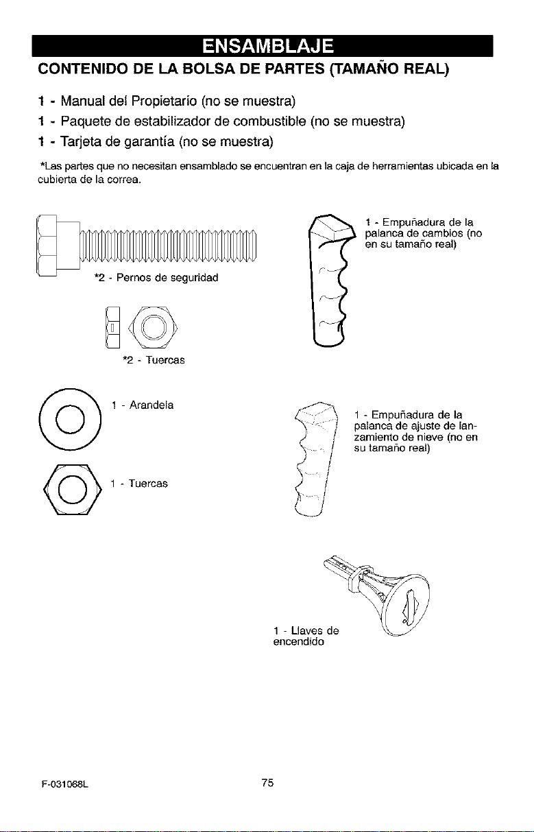
CONTENIDO DE LA BOLSA DE PARTES (TAMAt_IO REAL)
1 - Manual del Propietario (no se muestra)
1 - Paquete de estabilizador de combustible (no se muestra)
1 - Tarjeta de garantia (no se muestra)
*Las partes que no necesitan ensamblado se encuentran en la caja de herramientas ubicada en la
cubierta de la correa,
*2 - Pernos de seguridad
*2 - Tuercas
I 1 - EmpuSadura de la
palanca de cambios (no
en su tamaSo real)
F--
©
1 - Arandela
1 - Tuercas
1 - EmpuSadura de la
palanca de ajuste de lan-
zamiento de nieve (no en
su tamaSo real)
1 - L]avesde_
encendido
F-031068L 75
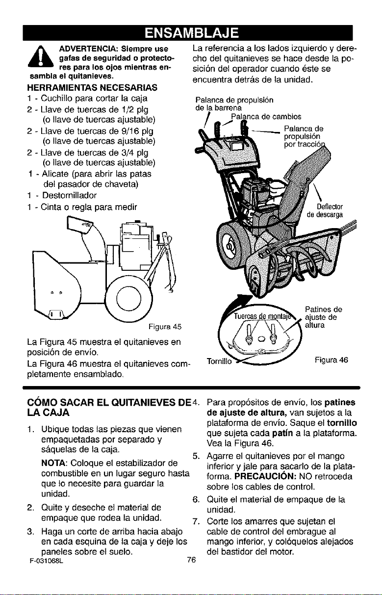
_b DVERTENCIA: Siempre use
gafas de seguridad o protecto-
res para los ojos mientras en-
sambla el quitanieves.
HERRAMIENTAS NECESAR|AS
1 - Cuchillo para cortar la caja
2 - Llave de tuercas de 1/2 pig
(o Ilave de tuercas ajustable)
2 - Llave de tuercas de 9/16 pig
(o Ilave de tuercas ajustable)
2 - Llave de tuercas de 3/4 pig
(o Ilave de tuercas ajustable)
1 - Alicate (para abrir las patas
del pasador de chaveta)
1 - Destornillador
1 - Cinta o regla para medir
Figura 45
La Figura 45 muestra el quitanieves en
posici6n de envio.
La Figura 46 muestra el quitanieves com-
pletamente ensamblado.
La referencia a los lados izquierdo y dere-
cho del quitanieves se hace desde la po-
sici6n del operador cuando 6ste se
encuentra detr&s de la unidad.
Palanca de propulsi6n
de la barrena
Palanca de
propulsi6n
Deflector
de descarga
Patines de
• ajuste de
altura
Figura 46
C_MO SACAR EL QUITANIEVES DE4.
LA CAJA
1. Ubique todas las piezas que vienen
empaquetadas por separado y
s&quelas de la caja.
NOTA: Coloque el estabilizador de
combustible en un lugar seguro hasta
que Io necesite para guardar ]a
unidad.
2. Quitey deseche el material de
empaque que rodea la unidad.
3. Haga un corte de arriba hacia abajo
en cada esquina de la caja y deje los
paneles sobre el suelo.
Fu031068L
5.
6.
7.
76
Para prop6sitos de envio, los patines
de ajuste de altura, van sujetos a la
plataforma de envio. Saque el tornillo
que sujeta cada pat|n a la plataforma.
Vea la Figura 46.
Agarre el quitanieves por el mango
inferior y jale para sacarlo de la plata-
forma. PRECAUCI(_N: NO retroceda
sobre los cables de control.
Quite el material de empaque de la
unidad.
Corte los amarres que sujetan el
cable de control del embrague al
mango inferior, y col6quelos alejados
del bastidor del motor.
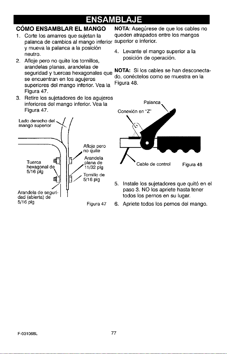
C6MO ENSAMBLAR EL MANGO NOTA: Aseg_rese de que los cables no
1. Corte los amarres que sujetan la queden atrapados entre los mangos
palanca de cambios al mango inferior superior e inferior.
y mueva la palanca a la posici6n
4. Levante el mango superior a la
neutro.
2. Afloje pero no quite los tornillos, posici6n de operaci6n.
arandelas planas, arandelas de
seguridad y tuercas hexagonales que NOTA: Si los cables se ban desconecta-
se encuentran en los agujeros do, conectelos como se muestra en la
superiores del mango inferior. Vea la Figura 48.
Figura 47.
3. Retire los sujetadores de los agujeros
inferiores del mango inferior. Vea la
Figura 47. Conexi6n en "Z"
mango superior
\
Afloje pero
no quite
Arandela
Arandela de segurid
dad aberta de
5/16 pig
Tuerca Cable de control Figura48
5/16pig , Tornillo de
5/16 pig
5. lnstale los sujetadores que quit6 en el
paso 3. NO los apriete hasta tener
todos los pernos en su lugar.
Figura 47 6. Apriete todos los pernos del mango.
F-031068L 77
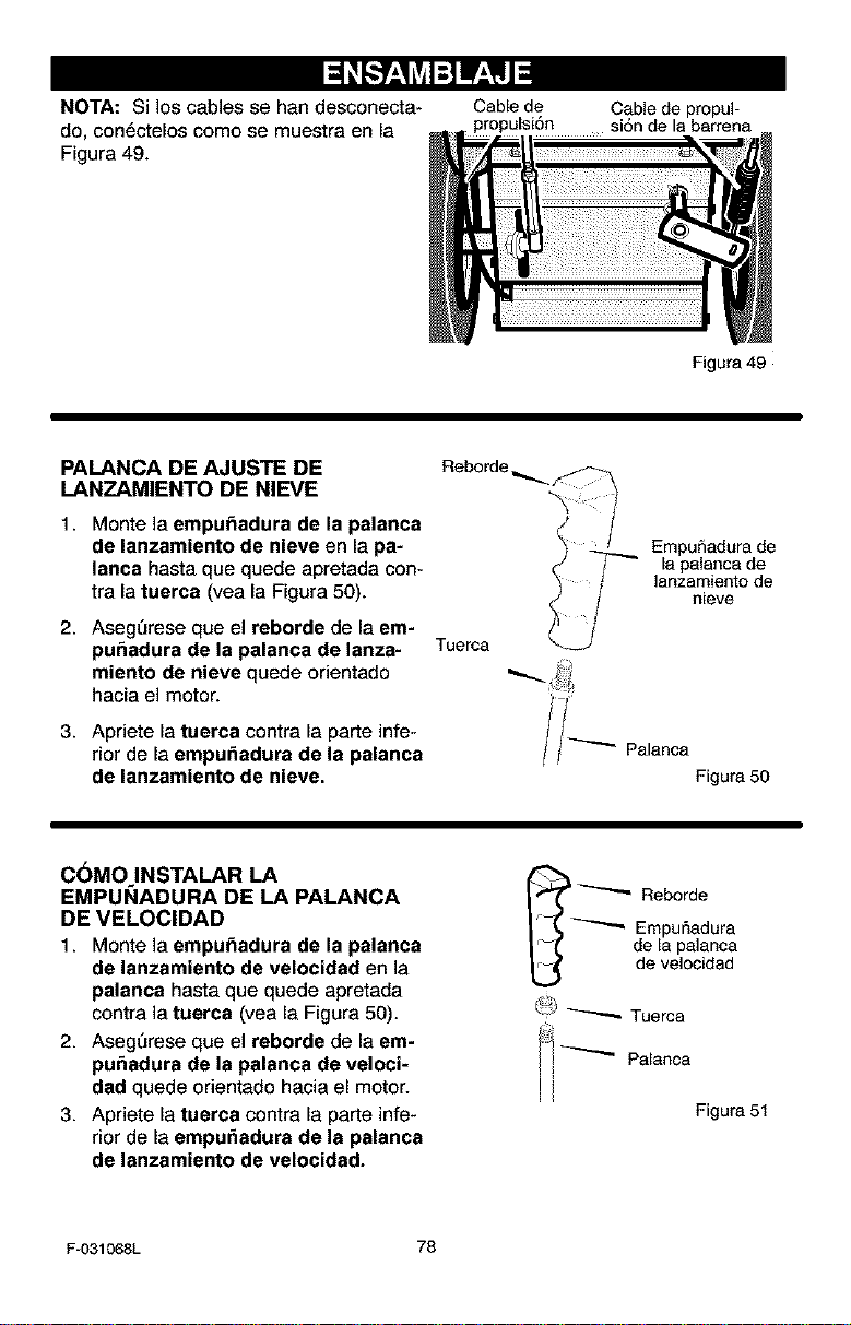
I::1 Lv4:]W_, IJ I
NOTA: Si los cables se han desconecta-
do, con_ctelos come se muestra en la
Figura 49.
Cable de
propulsi6n
Cable de propul-
si6n de la barrena
PALANCA DE AJUSTE DE
LANZAMIENTO DE NIEVE
1. Monte la empu_adura de la palanca
de lanzamiento de nieve en la pa-
lanca haste que quede apretada con-
tra la tuerca (yea la Figura 50).
2. AsegQrese que el reborde de la em-
pu_adura de la palanca de lanza-
miento de nieve quede orientado
hacia el motor.
3. Apriete la tuerca contra la parte infe-
rior de la empu_adura de la palanca
de lanzamiento de nieve.
Reborde
Tue_a
Figura 49
EmpuSadura de
la palanca de
lanzamiento de
nieve
Palanca
Figura 50
CbMO INSTALAR LA
EMPUI_IADURA DE LA PALANCA
DE VELOClDAD
1. Monte la empu_adura de la palanca
de lanzamiento de velocidad en la
palanca haste que quede apretada
contra la tuerca (yea la Figura 50).
2. Aseg_rese que el reborde de la em-
pu_adura de la palanca de veloci-
dad quede orientado hacia el motor.
3. Apriete la tuerca contra la parte infe-
rior de la empu_adura de la palanca
de lanzemiento de velocidad.
_"" Reborde
Empur_adura
de la palanca
de velocidad
_;;) _ Tuerca
Palanoa
'i
i
Figura 51
F-031068L 78
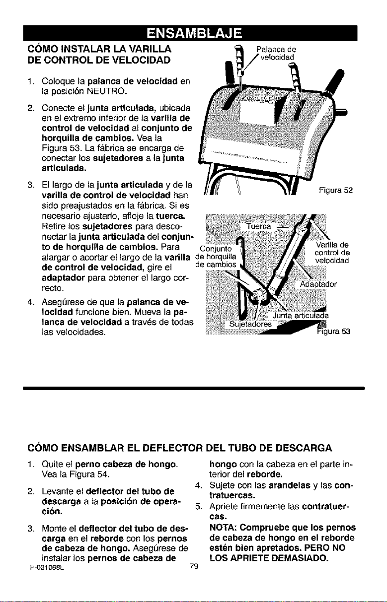
C6MO INSTALAR LA VARILLA
DE CONTROL DE VELOCIDAD
1. Coloque la palanca de velocidad en
la posici6n NEUTRO.
2. Conecte el junta articulada, ubicada
en el extremo inferior de la varilla de
control de velocidad al conjunto de
horquina de cambios. Vea la
Figura 53. La f_brica se encarga de
conectar los sujetadores a la junta
articulada.
3. El largo de la junta articulada y de la
varilla de control de velocidad han
sido preajustados en la f&brica. Si es
necesario ajustarlo, afloje la tuerca.
Retire los sujetadores para desco-
nectar la junta articulada del conjun-
to de horquilla de cambios. Para
alargar o acortar el largo de la varilla de hcrquilla
de control de velocidad, gire el de cambics
adaptador para obtener el largo cor-
recto.
4. AsegSrese de que la palanca de ve-
Iocidad funcione bien. Mueva la pa-
lanca de velocidad a trav_s de todas
las velocidades.
Palanca de
Figura 52
Varilia de
control de
velocidad
]Adaptador
Junta articulada
ujetadores
Figura 53
C6MO ENSAMBLAR EL DEFLECTOR
1. Quite el perno cabeza de hongo.
Yea la Figura 54.
4.
2. Levante el deflector del tubo de
descarga a la posicibn de opera- 5.
cion.
3. Monte el deflector del tubo de des-
carga en el reborde con los pernos
de cabeza de bongo. AsegSrese de
instalar los pernos de cabeza de
Fu031068L 79
DEL TUBO DE DESCARGA
hongo con la cabeza en el parte in-
terior del reborde.
Sujete con las arandelas y las con-
tratuercas.
Apriete firmemente las contratuer-
cas.
NOTA: Compruebe que los pernos
de cabeza de hongo en el reborde
esten blen apretados. PERO NO
LOS APRIETE DEMASIADO.
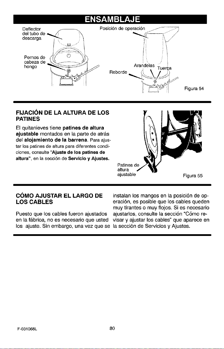
Pemos de
cabeza de
hongo
Posici6n de operaci6n .................;_
]
I S
Arandelas
Reborde_
Figura 54
FIJACI(_N DE LA ALTURA DE LOS
PATINES
El quitanieves tiene patines de altura
ajustable montados en la parte de atr&s
del alojamiente de la barrena. Para ajus-
tar los patinesde altura para diferentes condi-
ciones, consulte "Ajuste de los patines de
altura", en la secci6n de Servicio y Ajustes.
Patines de
altura
ajustable
Figura 55
C6MO AJUSTAR EL LARGO DE instalan los mangos en la posici6n de op*
LOS CABLES eraci6n, es posible que los cables queden
muy tirantes o muy flojos. Si es necesario
Puesto que los cables fueron ajustados ajustarlos, consulte la secci6n "C6mo re-
en la f&brica, no es necesario que usted visar y ajustar los cables" que aparece en
los ajuste. Sin embargo, una vez que se la secci6n de Servicios y Ajustes.
F-031068L 80
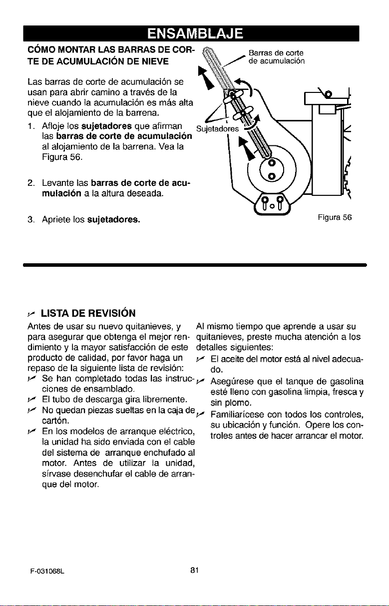
C(_MO MONTAR LAS BARRAS DE COR-
TE DE ACUMULACI(_N DE NIEVE
Las barras de corte de acumulaci6n se
usan para abrir camino a traves de la
nieve cuando la acumulaci6n es m&s aJta
que el alojamiento de la barrena.
1. Afioje los sujetedores que afirman
las barras de corte de acumulacion
al alojamiento de la barrena. Vea la
Figura 56.
2. Levante las barras de corte de acu-
mulacion a la altura deseada.
Barras de corte
Sujetadores
l
3. Apriete los sujetadores.
Figure, 56
_" LISTA DE REVISION
Antes de usar su nuevo quitanieves, y AI mismo tiempo que aprende a usar su
para asegurar que obtenga el mejor ren- quitanieves, preste mucha atenci6n a los
dimiento y la mayor satisfacci6n de este detalles siguientes:
producto de calidad, per favor haga un _" El aceite del motor est& al nivel adecua-
repaso de la siguiente lista de revisi6n: do.
_" Se hart completado todas las instruc-_, AsegQrese que el tanque de gasolina
clones de ensamblado, este Ileno con gasolina limpia, fresca y
_" El tube de descarga gira libremente, sin plomo.
_" No quedan piezas sueltas en la caja de_, Familiaricese con todos los controles,
cart6n, su ubicaci6n y funci6n. Opere los con-
_" En los modelos de arranque el_ctrico, troles antes de hacer arrancar el motor.
la unidad ha sido enviada con el cable
del sistema de arranque enchufado al
motor. Antes de utilizar la unidad,
sJrvase desenchufar el cable de arran-
que del motor.
F-031068L 81
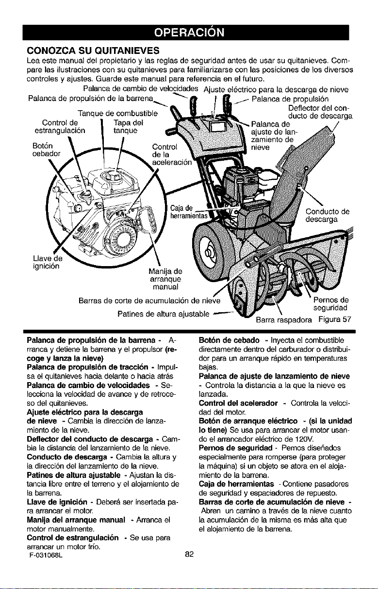
CONOZCA SU QUITANIEVES
Lea este manual del propietario y Ins reglas de seguridad antes de usar su quitanieves. Com-
pare Ins ilustraciones con su quitanieves para familiarizarse con Ins posiciones de los diversos
contreles y ajustes. Guarde este manual para referenela en el future.
Pelanca de cambb de velocidades Ajuste el6ctrico para la descarga de nieve
Palanca de _ Palanca de propulsi6n
Deflector del con-
Tanque de combustible ducto de descarga
Control de
estrangulaci6n
Bot6n
cebador
Conducto de
descarga
Uave de
igniel6n
Manila de
arrenque
manual
Barras de carte de acumulaci6n de nieve
Patines de altura ajustable
seguridad
Barra raspadora Figura 57
Palanca de propulsi6n de la barrena - A-
rranca y detiene la barrena y el propulsor (re-
cage y lanza la nieve)
Palanca de propulsibn de traecion - Impel-
sa el quitanieves habla delante o habla atrbs
Palanea de eambio de velocidades - Se-
lecciona la velocidad de avance y de retrese-
so del quitanieves.
Ajuste ef_-trico para la descarga
de nieve - Cambla la direcci6n de lanza-
miento de la nieve,
Deflector del conducto de descarga - Cam-
bin la distanbla del lanzamiento de la nieve.
Conducto de descarga - Cambla la altura y
la direcei6n del lanzamiento de ]a nieve,
Patines de altura ajustable - Ajustan ]a dis-
tancia libre entre el terreno y el alojamiento de
la barrena.
Mare de ignici6n - Deber& ser insertada pa-
re arrancar el motor.
Manila del arranque manual - Arranca el
motor manuelmente,
Control de estrangulaci6n - Se usa para
arrancar un motor frlo.
F-031068L
Botbn de cebado - Inyecta el combustible
directamente dentro del carburedor o distribui-
dot para un arranque r&pido en temperaturos
bsjas.
Palanca de ajuste de lanzamiento de nieve
- Contrela la distanbla a la que la nieve es
lanzada.
Control del acelerador - Controla la veloci-
dad del motor.
Botbn de arranque electrico - (el la unided
Io tiene) Se usa para arrancar el motor usan-
do el arrancador ek_c_r_o de 120V.
Pernos de segurided - Pemos diser_ados
especielmente para romperse (para prateger
la m&qelna) si un objeto se atora en el elaja-
mienta de ]a barrena.
Caja de herramiantas - Cantiene pasadores
de seguridad y espabladores de rebuesta.
Barraa de carte de acomulacibn de nieve -
Abren un camina a trav6s de ]a nieve cuanta
la asumulaci6n de ]a misma es mos elta que
el alojamientode la barrena.
82
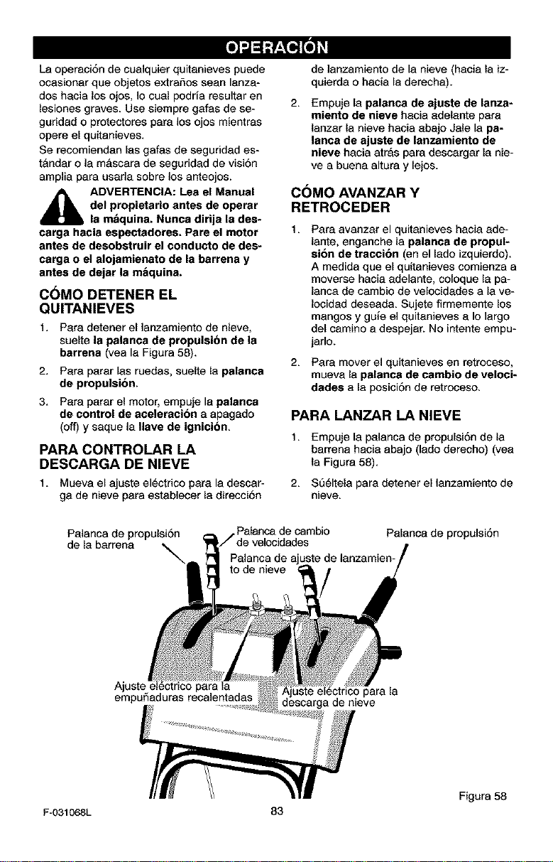
Laoperaci6ndecualquierquitanievespuede
ocasionarqueobjetosextraSosseanlanza-
doshacialosojas,]acualpodriaresultaren
lesianes graves. Use siempre gafas de se-
guridad o pratectores para ]as ajos mientras
opera el quitanieves.
Se recomiendan las gafas de seguridad es-
t&ndar o la mascara de seguridad de visi6n
amplia para usada sabre los anteajos.
_IL ADVERTENCIA: Lea el Manual
del propietario antes de operar
la m&quina. Nunca dirija la des-
carga hacia espectadores. Pare el motor
antes de desobstruir el conducto de des-
carga o el alojamienato de la barrena y
antes de dejar la m&quina.
C6MO DETENER EL
QUITANIEVES
1. Para detener el lanzamiento de nieve,
suelte la palanca de prepulsibn de la
barrena (yea la Figura 58).
2. Para parar las ruedas, suelte la palanca
de propulsibn.
3. Para parar el motor, empuje la palanca
de control de aceleracibn a apagado
(off) y saque ]a Ilave de ignicibn.
PARA CONTROLAR LA
DESCARGA DE NIEVE
1, Mueva el ajuste el_ctrico para la descar-
ga de nieve para establecer la direcci6n
de ]anzamiento de la nieve (hacia la iz-
quierda o haaia la derecha).
2. Empuje la palanca de ajuste de lanza-
miento de nieve hacia adelante para
lanzar la nieve hacia abajo Jale la pa-
lanca de ajuste de lanzamiento de
nieva hacia atrAs para descargar la nie-
vea buena altura y lejos.
CbMO AVANZAR Y
RETROCEDER
1,
2,
Para avanzar el quitanieves hacia ade-
lante, enganche la palanca de propul-
sion de traccibn (an el lado izquierdo).
A medida que el quitanieves comienza a
moverse hacia adelante, coloque la pa-
lanca de cambio de velocidades a la ve-
Iocidad deseada. Sujete firmemente los
mangos y guie el quitanieves a Io largo
del camino a despejar. No intente empu-
jarlo.
Para mover el quitanieves en retroceso,
mueva la palanca de cambio de veloci-
dades a la posici6n de retroceso.
PARA LANZAR LA NIEVE
1. Empuje la palanca de propulsi6n de la
barrena hacia abajo (lade derecho) (yea
la Figura 58).
2. S5_ltela para detener el ]anzamiento de
nieve.
Palanca de propulsi6n
de la barrena ,,.
\
,Palanca de cambio
Palanca de propulsi6n
empuSaduras recalentadas
para la
descarga de nieve
/ Figura 58
F-O31068L 83
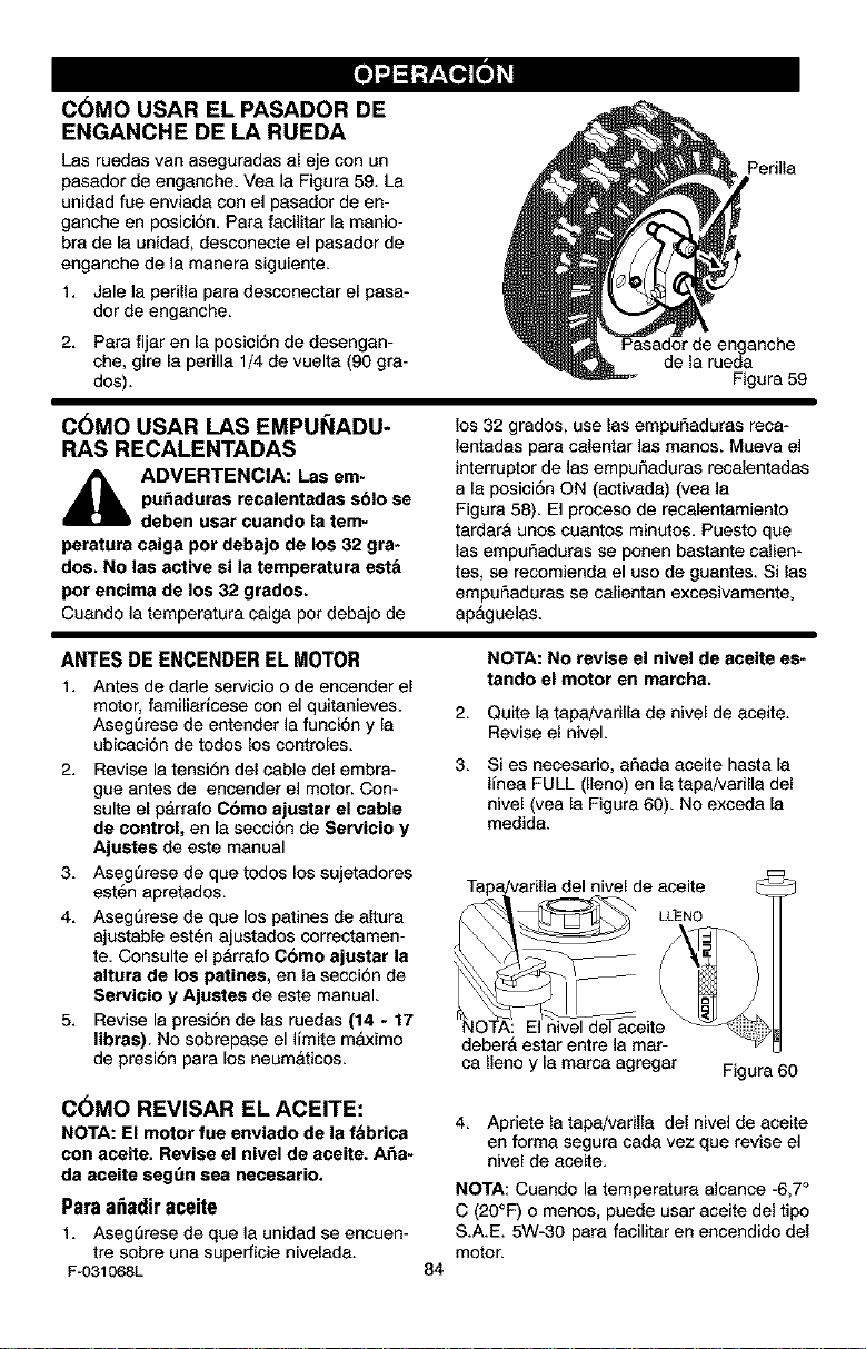
C6MO USAR EL PASADOR DE
ENGANCHE DE LA RUEDA
Las ruedas van aseguradas al eje con un
pasador de enganche. Vea la Figura 59. La
unidad fue enviada con el pasador de en-
ganche en posici6n. Para facilitar la manio-
bra de la unidad, desconecte el pasador de
enganche de la manera siguiente.
1. Jale la perilla para desconectar el pasa-
dor de enganche.
2. Para fijar en la posici6n de desengan-
che, gire la perilla 1/4 de vuelta (90 gra-
des).
Perilla
Pasador de enganche
de la rueda
Figura 59
C6MO USAR LAS EMPUI_IADU-
RAS RECALENTADAS
_ DVERTENClA: Las em-
pu_aduras recalentadas sblo se
deben usar cuando la tem-
peratura caiga per debajo de los 32 gra*
dos. No las active si la temperatura est_
per encima de los 32 grades.
Cuando la temperatura caiga per debajo de
los 32 grades, use las empufiaduras reca-
lentadas para calentar las manes. Mueva el
interrupter de las empufiaduras recalentadas
a la posici6n ON (activada) (yea la
Figura 58). El proceso de recalentamiento
tardarA unos cuantos minutes. Puesto que
las empufiaduras se ponen bastante calien-
tes, se recomienda el use de guantes. Si las
empufiaduras se calientan excesivamente,
apAguelas.
ANTES DE ENCENDER EL MOTOR
1, Antes de darle servicie e de eneender el
motor, familiaricese con el quitanieves.
AsegSrese de entender la funci6n y la
ubicaci6n de todos los controles.
2. Revise la tensi6n del cable del embra-
gue antes de encender el motor. Con-
suite el parrafo C6mo ajustar el cable
de control, en la secci6n de Servicio y
Ajustes de este manual
3, AsegSrese de que redes los sujetaderes
est6n apretados,
4, AsegSrese de que los patines de aitura
ajustable est_n ajustados cerrectamen-
te, Censulte el parrafe C6mo ajustar la
altera de los patines, en la secci6n de
Servicio y Ajustes de este manual.
5, Revise la presi6n de las ruedas (14 - 17
libras). No sobrepase el limite mAximo
de presi6n para los neumaticos.
C6MO REVISAR EL ACEITE:
NOTA: El motor fue enviado de la f_brica
con aceite. Revise el nivel de aceite. A_a-
da aceite segt_n sea necesario.
Paraa_adiraceite
t, AsegSrese de que ]a unidad se encuen-
tre sobre una superficie nivelada.
F-031068L
NOTA: No revise el nivel de aceite es-
tando el motor en marcha.
2. Quite la tapajvarilla de nivel de aceite.
Revise el niveL
3. Si es necesario, afiada aceite hasta la
linea FULL (lleno) en la tapa/varilla del
nivel (vea la Figura 60). No exceda la
medida.
_de _L_ei_=d_
NOTA: El nive de aceite --%
deberA estar entre la mar-
ca Ileno y la marca agregar Figura 60
84
4, Apriete la tapa/varilla del nivel de aceite
en forma segura cada vez que revise el
nivel de aceite,
NOTA: Cuando la temperatura alcance -6,7°
C (20°F) o menos, puede usar aceite del tipo
S.A.E. 5W-30 para facilitar en encendido del
motor.

"J
TIPO DE COMBUSTIBLE
La certificaci6n del motor indice que 6ste
cumple con las estipulaciones de las normas
de regulaci6n de emisiones de California y
de la US EPA pare motores ULGE (en equi-
po de servicio opara prados y jardines). Los
motores ULGE est&n certificados pare fun-
cionar con gasoline regular sin plomo.
_lb DVERTENClA: Los combusti-
bles mezclados con alcohol
(llamados gasohol o aquellos
que usan etanol o metanol) pueden
atraer humedad la cual conduce a la se-
paracion y formacion de bcidos durante
el almacenamiento. Los gases acldicos
pueden da_ar el sistema de combustible
de un motor mientras se encuentra en
almacenamiento.
NOTA: Pare evitar problemas del motor, el
sistema de combustible debe vaciarse antes
del almacenamiento durante 30 dies o ma-
yor. Arranque el motor y d6jelo en marcha
hasta que las lineas de combustible y el
carburador est6n vacios. Use gasolina fres-
ca la siguiente temporada.(vea la "lnstruccio-
nes para almacenamiento" pare obtener
informaci6n adicional).
Nunca use productos de limpieza de motor o
carburador en el tanque de combustible, de
Io contrario podria causer daSo permanente.
Llenar el tanque _nicamente con gasoline
nueva, ]impia, regular sin piomo, super sin
plomo, o gasoline automotor reformulada.
NO usa gssolina con plomo. AsegSrese de
que el recipiente que contiene la gasoline a
utilizar, est6 limpio y sin 6xido u otras
particulas extrar_as. Nunca use gasoline
vencida debido a su prolongado almacena-
miento.
DepSsito
de gasoline
\
ADVERTENCIA: La gasoline es
inflamable y debe tener mucho
cuidado al manipularla o
alamcenarla.
No Ilene el tanque de combustible
mientras el quitanieves se encuentre
en marcha, cuando est_ caliente, o
cuando el quitanieves se encuentre
en un area cerrada.
Mantenga la unidad alejada de llamas
abiertas o chispas el_ctricas y no fu-
me mientras liens el tanque de com-
bustible.
Nunca Ilene el tanque completamente,
Llene el tanque hasta dejar entre
1/4-1/2 pulgada de la parte superior
para proporcionar espacio pare la ex-
pansion del combustible.
Siempre Ilene el tanque al aire libre y
use un embudo o boquilla para preve-
nit el derrame.
Asegt_rese de limpiar cualquier com-
bustible derramado antes de arrancar
el motor.
Almacene la gasolina en un conten-
dor, limpio y aprobado, y mantenga la
tapa puesta y segura en el
contenedor.
Figura 61
F-031068L 85
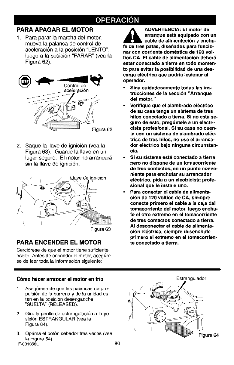
PARA APAGAR EL MOTOR
1. Para parar la marcha del motor,
mueva la palanca de control de
aceleraci6n a la posici6n "LENTO",
]uego a la posici6n "PARAR" (vea la
Figura 62).
Figura 62
2. Saque la Ilave de ignici6n (vea la
Figura 63). Guarde la Ilave en un
]ugar seguro. El motor no arrancar&
sin la Ilave de ignici6n.
f ( ri_nici6n
Figura 63
PARAENCENDERELMOTOR
Cerci6rese de que el motor tiene suficiente
aceite. Antes de encender el motor, asegQre-
se de leer toda la informaci6n siguiente:
_lb DVERTENCIA: El motor de
arranque est& equipado con un
cable de alimentacion y enchu-
fe de tres patas, dise_ados para funcio*
nat con corriente dom_stica de 120 vol-
tios CA. El cable de alimentacibn deber&
estar conectado a tierra en todo momen-
to para evitar la posibilidad de una des-
carga el_ctrica que podria lesionar al
operador.
Siga cuidadosamente todas las ins-
trucciones de la seccibn "Arranque
del motor."
Verifique que el alambrado el_ctrico
de su casa tenga un sistema de tres
hilos conectado a tierra. Si no est_ se-
guro de esto, preguntele a un electri-
cista profesionaL Si su casa no cuen-
ta con un sistema de alambrado el_c-
trico de tres hilos, no use el arranca*
dor electrico bajo ninguna circunstan-
cia.
Si su sistema est& conectado a tierra
pero no dispone de un tomacorriente
de tres contactos, en un punto conve-
niente para enchufar su arrancador
el_ctrico, pida a un electricista profe-
sional que le instale uno.
Para conectar el cable de alimenta-
cibn de 120 voltios de CA, siempre
conecte primero el cable a la caja del
tomacorriente del motor, luego enchu-
fe el otro extremo en el tomacorriente
de tres contactos conectado a tierra.
AI desconectar el cable de alimenta-
cibn el_ctrica, siempre desenchufe
primero el extremo en el tomacorrien-
te conectado a tierra.
C6mohacerarrancarelmotorenfrio
1, AsegQrese de que las palancas de pro-
pulsi6n de la barrena y de la unidad es-
t&n en la posici6n desenganche
"S UELTA" (RELEASED).
2. Gire la perilla de estrangulaci6n a la po-
sici6n ESTRANGULAR (vea la
Figura 64).
Estrangulador
#
3, Oprima el bot6n cebador tres veces (yea
la Figura 64),
F-031068L 86
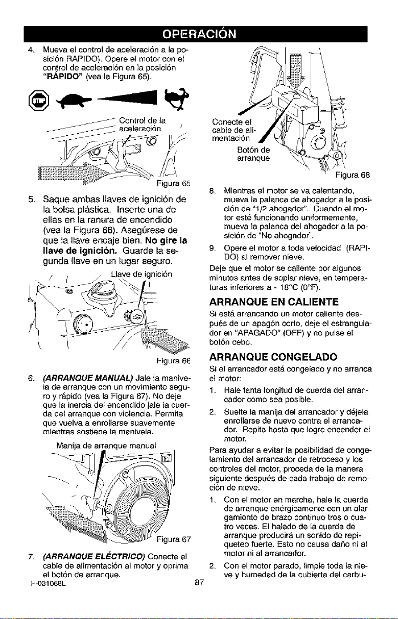
-.1
4. Mueva el control de aceleraci6n a ]a po-
sici6n RAPIDO). Opere el motor con el
con.trol de aceleraci6n en la posici6n
"RAPIDO" (yea la Figure 65).
_ ontrol de la
aceleraci6n
Figure 65
5. Saque ambas Ilaves de ignici6n de
]a boise pl&stica. Inserte una de
elias en la ranura de encendido
(vea la Figura 66). AsegQrese de
que la Ilave encaje bien. No gire la
gave de ignicibn. Guarde la se-
gunda Ilave en un lugar seguro.
f ( Uave de ignici6n
Figure 66
6. (ARRANQUE MANUAL) Jale la menive-
la de arranque con un movimiento segu-
roy r&pido (yea ]a Figure 67). No deje
que le inercia del encendido jale la cuer-
da del arranque con violencia. Permita
que vuelva a enrollarse suavemente
mientras sostiene la manivela.
Manija de arrar manual
Figura 67
7. (ARRANQUE ELECTRICO) Conecte el
cable de alimentaci6n al motor y oprima
el bot6n de arranque.
F-031068L
87
Conecte el
cable de ali-
mentaci6n
Bot6n de
arranque
Figure 68
8. Mientras el motor se va celentando,
mueva la palanca de ahogador ala posi-
ci6n de "I/2 ahogador". Cuando el mo-
tor est6 funcionando uniformemente,
mueva la palanca del ahogador ala po-
sici6n de "No ahogador".
9. Opere el motor a toda velocidad (RAPI-
DO) el remover nieve.
Deje que el motor se caliente pot algunos
minutos antes de soplar nieve, en tempera-
turas inferiores a - 18°C (0°F).
ARRANQUE EN CALIENTE
Siesta arrancando un motor celiente des-
pu6s de un apag6n corto, deje el estrangula-
dor en "APAGADO" (OFF) y no pulse el
bot6n cebo.
ARRANQUE CONGELADO
Si el arrancador esta congelado y no arranca
el motor:
1. Hale tanta Iongitud de cuerda del arran-
cador come sea posible.
2. Suelte la manija del arrancador y d_jela
enrollarse de nuevo contra el arranca-
dor. Repita haste que Iogre encender el
motor.
Pare ayuder a evitar la posibilided de conge-
lamiento del arrancedor de retroceso y los
controles del motor, proceda de la manera
siguiente despu_s de cada trabajo de remo-
ci6n de nieve.
1, Con el motor en marcha, hale la cuerda
de arranque en_rgicamente con un alar-
gamiento de braze continuo tres o cua-
tro veces. El halado de la cuerda de
arranque producira un sonido de repi-
queteo fuerte, Esto no causa dafio ni al
motor ni al arranoedoE
2, Con el motor parado, limpie toda la nie-
ve y humedad de la cubierta del carbu-
-.l
redor en el &rea de las palancas de
control. Asimismo, mueve el control de
acelereci6n, control de estrengulaci6n> y
menija del arrancador varias veces y de-
je el estrangulador en la posici6n, "TO-
TAL" (FULL) y la palanca de aceleraci6n
el la posici6n (RAPIDO).
_i ADVERTENCIA: Nunca arran-
que el motor dentro de un re-
cinto cerrado o en Areas con
poca ventilacibn. Los gases de escape
del motor contienen MONOXIDO DE
CARBONO, UN GAS INODORO Y MOR-
TAL. Mantenga las manes, los pies, el
pelo y las ropas sueltas alejadas de las
partes en movimiento tanto del motor
como del quitanieves.
La temperatura del silenciador y de
las piezas alrededor del silenciador
peede exceder los 150°[_. Evite tocar
estas partes.
NO PERMITA que ni_os ni adolescen-
tes operen el quitanieves ni que est_n
cerca cuando est_ funcionando.
C6MO RETIRAR OBJETOS
ATASCADOS DE LA BARRENA
ADVERTENClA: No intente qui-
tar ningl_n objeto que se haya
atorado en la barrena sin tomar
as precaeciones siguientes:
Suelte la pelance de propulsi6n de le be-
rreRe.
Mueva la palanca de control de acelera-
ci6n a la posici6n "perar".
Retire (sin girar) ]a Ilave de ignici6n.
Desconecte el cable de la bujfe.
No coloque las manos en la barrena o
canal de descerga. Use una barre de
apalancamiento pare secar el objeto
atescado.
RECOMENDACIONES SOBRE EL
LANZAMIENTO DE NIEVE
1. Pare mayor eficiencia de lanzamiento de
nieve durante la remoci6n de la misma,
ajuste la velocidad en el terreno, NUN-
CA le eceleraci6n. Avance lentemente
en nieve profunda, congelada, o h_me-
de. Si patinan las ruedas, reduzca la ve-
Iocidad de avarice. El motor est&
disefiado pare brindar un rendimiento
m_.ximo bajo acelereci6n total y debe
ser operado en este valor de potencia
en todo momento.
6,
2. El lanzamiento de nieve es mAs eficente 7.
si le remoci6n de la misma se efect5a
inmediatamente despu_s de su cafda.
3. Pare une remoci6n completa de le nieve,
traslape Iigeramente cede camino adop-
tado previamente. En nieve profunda,
superponga los barridos entre sf pare 8.
evitar sobrecargar la m&quina.
4. La nieve deberfa ser descargada en la 9.
direcci6n del viento siempre que sea po-
sible.
5. Pare uso normal, posicione los patines
de altura ajustable de manere tal que le
barre raspedora se encuentre 1/8 de
F-031068L
88
pulgada sobre los patines. Para superfi-
cies de nieve sumamente compacta,
ajuste los patines hacia arriba de mane-
re que la berra raspadora haga contecto
con el terreno.
En superficies de greva o roca triturada,
posicione los patines a I-1/4 pulgades
por debejo de la barre respadora (Vea el
p&rrafo "C6mo ajustar la altura de las
correderas de epoyo" en la pAgina 55).
Las rocas y grava no deberan ser reco-
gidas y ]anzadas por la m&quina.
Despu_s de que se haya completado el
lanzamiento de nieve, permita que el
motor se encuentre en reposo por unos
cuantos minutos, Io cual derretira la nie-
ve y hielo acumulado del motor.
Efect_e una limpieza completa de el qui-
tanieves luego de cada uso.
Remueva la ecumulaci6n de hielo y nie-
ve y todo material extraSo heterog6neo
de el quitanieves en su totalidad, y lave
con agua (si fuese posible) pera remo-
ver toda sel u otres substancies qufmi-
cas. Seque el quitenieves.
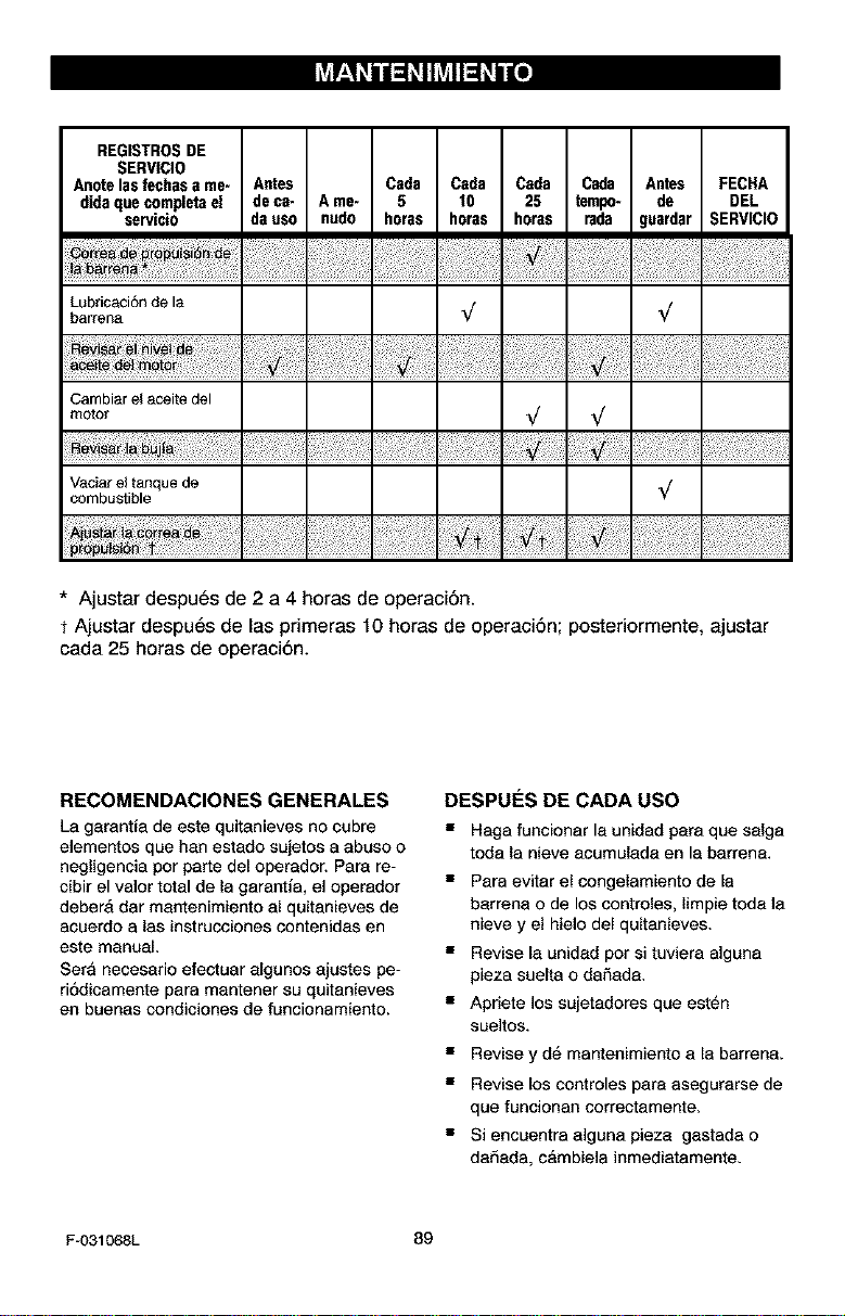
hViI__!I ii ;I 11hVlll;II i I[I]
REGISTROSDE
SERVICIO
Anotelas techas a me- Antes Csda Csda Csda Cada Antes FECHA
didaque completeel de ca- A me- 5 10 25 tempo- de DEL
servicio da uso nudo horas horas horas rada guardar SERVICIO
Lubricacidnde la
barrena %/ %/
Cambiar el aceite del
motor %/ %/
Vaciarel tanquede _/
combustible
¥
* Ajustar despues de 2 a 4 horas de operaci6n.
t Ajustar despues de las primeras 10 horas de operaci6n; posteriormente, ajustar
cada 25 horas de operaci6n.
RECOMENDACIONES GENERALES
La garantfa de este quitanieves no cubre
elementos que han estado sujetos a abuso o
negligencia por parte del operador. Parr re-
cibir el valor total de la garantfa, el operador
deber& dar mantenimiento al quitanieves de
acuerdo a las instrucciones contenidas en
este manual.
Sera necesario efectuar algunos ajustes pe-
ri6dicamente parr mantener su quitanieves
en buenas condiciones de funcionamiento.
DESPUF:S DE CADA USO
• Haga funcionar la unidad parr que salga
toda la nieve acumulada en la barrena.
• Parr evitar el congelamiento de la
barrena o de los controles, limpie toda la
nieve y el hielo del quitanieves.
• Revise la unidad pot si tuviera alguna
pieza suelta o daSada.
• Apriete los sujetadores que est_n
sueltos.
• Revise y d6 mantenimiento a la barren&
• Revise los controles parr asegurarse de
que funcionan correctamente.
• Si encuentra alguna pieza gastada o
daSada, c&mbiela inmediatamente.
F-O31068L 89
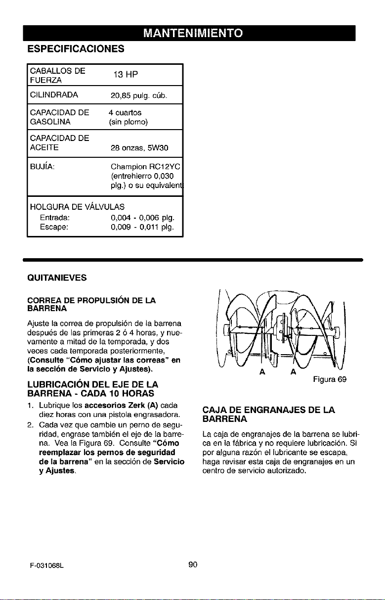
hV_r__!_ii_ IhV_ll_ i lie]
ESPECIFICAClONES
CABALLOS DE 13 HP
FUERZA
;ILINDRADA 20,85 pulg. cub.
CAPACIDAD DE 4 cuartos
GASOLiNA (sin plomo)
CAPACIDAD DE
ACEITE 28 onzas, 5W30
BUJIA: Champion RC12YC
(entrehierro 0,030
pig.) o su equivalen
HOLGURA DE V,_LVULAS
Entrada: 0,004 - 0,006 pig.
Escape: 0,009 - 0,011 pig.
QUITANIEVES
CORREA DE PROPULSI6N DE LA
BARRENA
Ajuste ]a correa de propulsi6n de la barrena
despots de las primeras 2 6 4 horas, y nue-
vamente a mitad de la temporada, y dos
veces cada temporada posteriormente,
(Consulte "Cbmo ajustar las correas" en
la secci6n de Servicio y Ajustes).
LUBRICACI(SN DEL EJE DE LA
BARRENA - CADA 10 HORAS
1, Lubrique los accesorios Zerk (A) cada
diez horas con una pistola engrasadora.
2. Cada vez que cambie un pemo de segu-
ridad, engrase tambi6n el eje de la barre-
ha. Vea [a Figura 69. Consulte "Cbmo
reemplazar los pernos de seguridad
de la barrena" en la secsiSn de Servicio
y Ajustes,
A A
Figura 69
CAJA DEENGRANAJESDELA
BARRENA
La caja de engranajes de la barrena se lubri-
ca en la f&brica y no requiere lubricaciSn. Si
par aiguna raz6n el [ubricante se ascap&
haga revisar esta caja de engranajes en un
centro de servicio autorizado.
F-O31068L 90
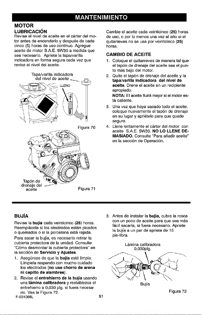
hV_r__!_ii_ IhV_ll_ i I[e_
MOTOR
LUBRICACI(SN
Revise el nive] de aceite en el carter de] mo-
tor antes de encendedo y despu6s de cada
cinco (5) horas de uso continuo, Agregue
aceite de motor S.A.E. 5W30 e medida que
sea necesario. Apriete ]a tapa/varilla
indicadora en forme segura cada vez que
revise el nivel del eceite.
Tapa/varilla indicadore
del nivel de aceite _
[_
LLENO --
Tap6n de I
drenajedel
aceite
Figure 70
Figure 71
Cambie el aceite cada veimicinco (25) horas
de uso, o por Io menos une vez al argo si el
quitanieves no se usa por veinticinco (25)
horas,
CAMB|O DE ACEITE
1. Coloque el quitanieves de manera tel que
el tap6n de drenaje del eceite see el pun-
to mAs bajo del motor.
2. Quite el tap6n de drenaje del aceite y le
tapa/varilla indicadora del nivel de
aceite, Drene el eceite en un recipiente
apropiado.
NOTA: El aceite fluirA mejor si el motores-
t& caliente.
3. Una vez que haya sacado todo el aceite,
coloque nuevamente el tap6n de drenaje
en su lugar y epri_telo pare que quede
seguro.
4. Uene lentamente el carter del motor con
aceite S.A.E. 5W30. NO LO LLENE DE-
MASIADO. Consulte "Pare a6adir eceite"
en le secci6n de Operaci6n.
BUJiA
Revise le bujia cada veinticinco (25) horas.
Reemplacela si los electrodos estan picados
o quemedos o si la porcelana estA rajada.
Pare secar la bujia, es necesario retirar la
cubierta protectora de la unidad. Consulte
"C6mo desmontar le cubierta protectora" en
la secci6n de Servicio y Ajustes,
1. Asegt3rese de que le bujia est6 limpia.
Limpiela raspando con mucho cuidedo
los eleetrodos (no use chorro de arena
ni cepillo de alambres).
2. Revise el entrehierro de la bujia usando
una I&mina calibradora y restablezoa el
entrehierro a 0,030 pig. si fuera necesa-
rio. Vea la Figure 72.
F-031068L
3. Antes de instalar la bujia, cubra la rosca
con un poco de aceite pare que sea m&s
facil sacarla, si fuera necesado. Apriete
la buj{a e un par de epriete de 15
pie-libra.
Lkmina calibradore
0,030pig.
91
Bui{a
Figure 72
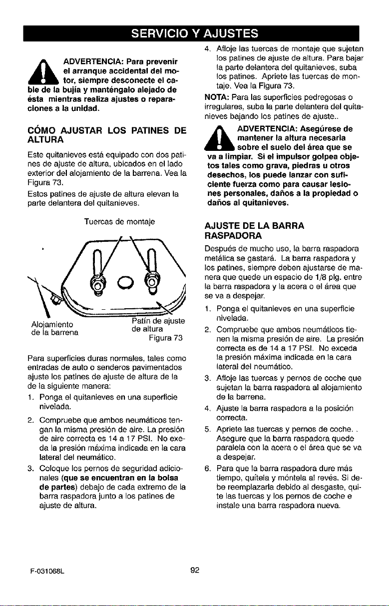
_lb ADVERTENCIA: Para prevenir
el arranque accidental del mo-
tor, siempre desconecte el ca*
ble de la bujia y mantengalo alejado de
esta mientras realiza ajustes o repara-
clones a la unidad.
C(_MO AJUSTAR LOS PATINES DE
ALTURA
Este quitanieves est& equipado con dos pati-
nes de ejuste de eltura, ubicedos en el lado
exterior del alojamiento de la barrene. Vea le
Figure 73.
Estos patines de ajuste de altura eleven la
parte delantere del quitenieves.
Tuercas de montaje
O
Pet[n de ajuste
Alojamiento
de le berrena de altura
Figura 73
Pare superficies duras normeles, tales como
entradas de auto o senderos pavimentados
ajuste los petines de ajuste de altura de la
de la siguiente manere:
1. Ponga el quitanieves en una superficie
nivelada.
2. Compruebe que embos neumaticos ten-
gan la misma presi6n de aire. La presi6n
de eire correcta es 14 a 17 PSL No exe-
dala presi6n maxima indiceda en la cara
lateral del neumatico.
3. Coloque los pemos de seguridad adicio-
hales (que se encuentran en la bolsa
de partes) debajo de ceda extremo de le
barra raspadora junto a los petines de
ejuste de eltura.
4. Afloje les tuercas de montaje que sujetan
los patines de ajuste de altura. Para bajar
la perte delantere del quitenieves, sube
los patines. Apriete ]as tuercas de mon-
teje. Vea la Figura 73.
NOTA: Pare las superficies pedregosas o
irregulares, suba le perte delentera del quita-
nieves bajendo los patines de ajuste-
_hk DVERTENOIA: Aseg_rese de
mantener la altura necesaria
sobre el suelo del &rea qee se
va a limpiar. Si el impulsor golpea obje-
tos tales como grava, piedras u otros
desechos, los puede lanzar con sufi-
ciente fuerza come para causar lesio-
nes personales, da_os a la propiedad o
da_os al quitanieves.
AJUSTE DE LA BARRA
RASPADORA
Despu_s de mucho uso, la barra raspadora
metalica se gestar& La barra respadora y
los patines, siempre deben ajustarse de ma-
nera que quede un espacio de 1/8 pig. entre
la barra raspadore y le acere o el Area que
se vaa despejan
1,
2.
Ponga el quitanieves en una superficie
nivelada.
Compruebe que ambos neumaticos tie-
hen la misma presi6n de aire. Le presi6n
correcta es de 14 e 17 PSI. No excede
la presi6n maxima indiceda en la cara
lateral del neumatico.
3. Afloje les tuercas y pernos de coche que
sujetan la berra raspadora al alojamiento
de la barren&
4. Ajuste le barra raspadora ala posici6n
correcta.
5. Apriete ]as tuercas y pernos de coche..
Asegure que la barra raspadora quede
paralela con la acera o el Area que se va
a despejar.
6. Para que la barre raspedore dure mas
tiempo, quitela y m6ntele al rev_s. Si de-
be reemplazarle debido al desgeste, qui-
te las tuercas y los pemos de coche e
instale una barra raspadore nueve.
F-031068L 92
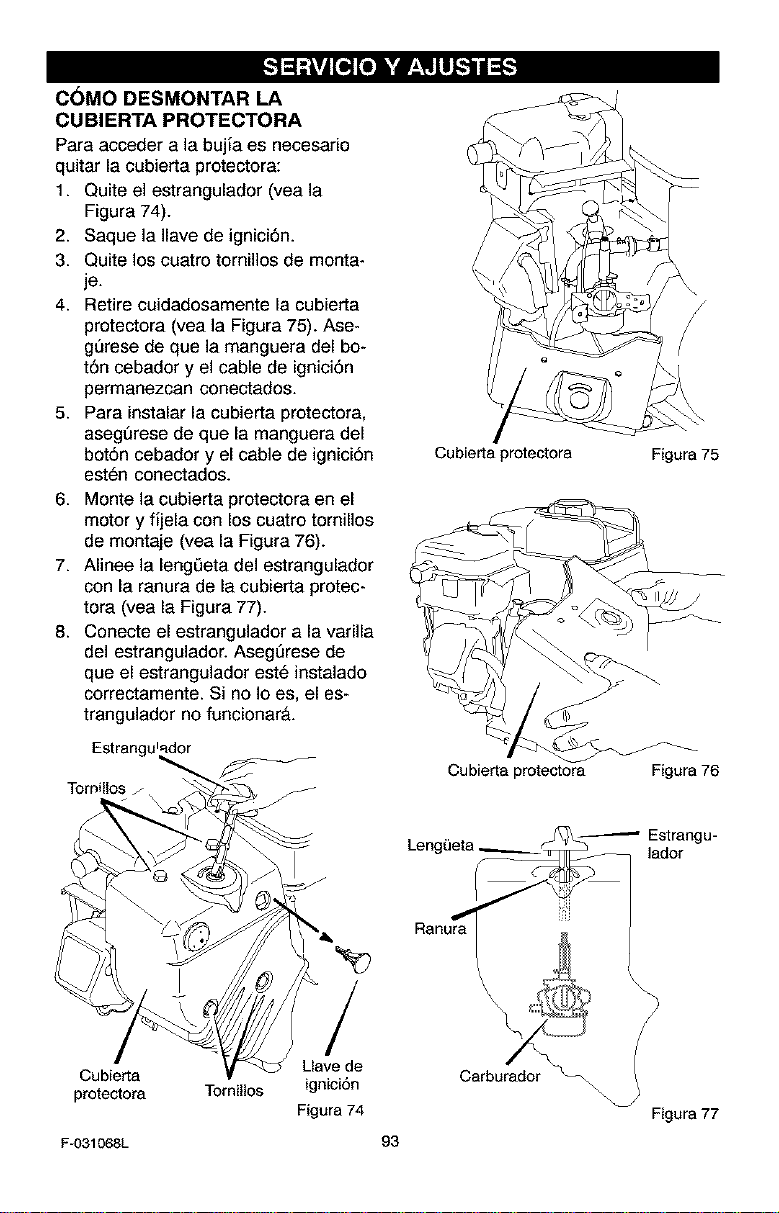
C6MO DESMONTAR LA
CUBIERTA PROTECTORA
Para acceder a la bujia es necesario
quitar la cubierta protectora:
1. Quite el estrangulador (vea la
Figura 74).
2. Saque la Ilave de ignici6n.
3. Quite los cuatro tornillos de monta-
je.
4. Retire cuidadosamente la cubierta
protectora (vea la Figura 75). Ase-
gQrese de que la manguera del be*
t6n cebador y el cable de ignici6n
permanezcan conectados.
5. Para instalar la cubierta protectora,
asegQrese de que la manguera del
bot6n cebador y el cable de ignici6n
esten conectados.
6. Monte la cubierta protectora en el
motor y fijela con los cuatro tornillos
de montaje (vea la Figura 76).
7. Alinee la leng0eta del estrangulador
con la ranura de la cubierta protec-
tora (vea la Figura 77).
8. Conecte el estrangulador a la varilla
del estrangulador. AsegQrese de
que el estrangulador este instalado
correctamente. Si no Io es, el es-
trangulador no funcionar&.
Estrangu_dor
TomiUos
Cubierta protectora Figura 75
Cubierta protectora Figura 76
_ Estrangu-
Leng_eta -- ]ador
Ranur_a
Cubierta
protectora Tornillos
Fu031068L
/
Llave de
ignici6n
Figura 74
\
Carburador_\\
\
93
Figura 77
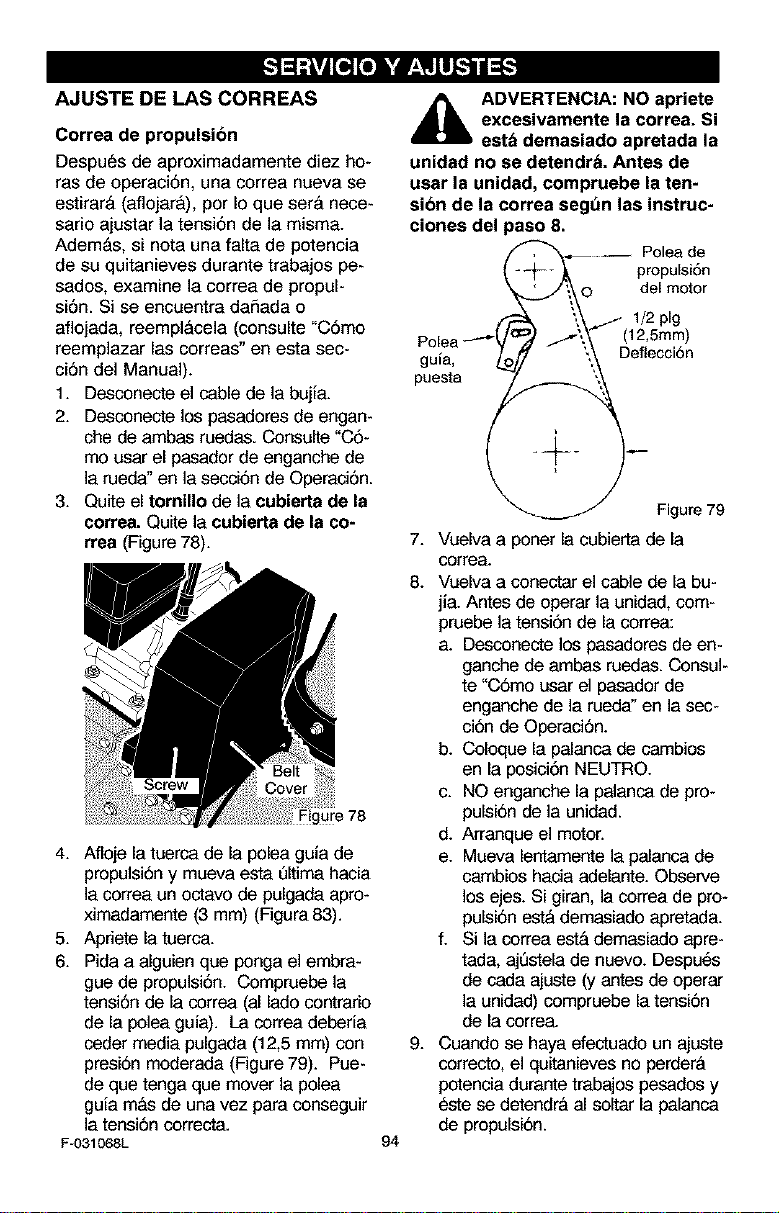
AJUSTE DE LAS CORREAS
Correa de propulsion
Despues de aproximadamente diez ho-
ras de operaci6n, una correa nueva se
estirar& (aflojar&), por Io que ser& nece-
sario ajustar la tensi6n de la misma.
Adem&s, si nota una falta de potencia
de su quitanieves durante trabajos pe-
sados, examine la correa de propul-
si6n. Si se encuentra daSada o
aflojada, reempl&cela (consulte "C6mo
reemplazar las correas" en esta sec-
ci6n del Manual).
1. Desconecte el cable de la bujia.
2. Desconecte los pasadores de engan-
che de ambas ruedas. Consuite "C6-
mo usar el pasador de enganche de
]a rueda" en la secci6n de Operaci6n.
3. Quite el tornillo de la cubierta de la
correa. Quite la cubierta de la co-
rrea (Figure 78).
4. Afloje la tuerca de la polea guia de
propulsi6ny mueva esta Qitima hacia
]a correa un octavo de pulgada apro-
ximadamente (3 mm) (Figura 83).
5. Apriete la tuerca.
6. Pida a alguien que ponga el embra-
gue de propulsi6n. Compruebe la
tensi6n de la correa (al lado contrario
de la polea guia). La correa deberia
ceder media pulgada (12,5 mm) con
presi6n moderada (Figure 79). Pue-
de que tenga que mover la polea
guia m&s de una vez para conseguir
la tensi6n correcta.
F-031068L
94
_ll ADVERTENClA: NO apriete
excesivamente la correa. Si
est& demasiado apretada la
unidad no se detendr& Antes de
usar la unidad, compruebe la ten-
sion de la correa segt_n las instruc-
clones del paso 8.
_ Poleade
-- ._ propulsi6n
J'\_o del motor
/', (12,5mm)
g _ '.,
P°liea o \ Defecc 6n
puesta ,___
Figure 79
7. Vuelva a paner la cubierta de la
correa.
8. Vuelva a conectar el cable de la bu-
jia. Antes de operar la unidad, com-
pruebe la tensi6n de la correa:
a. Desconecte los pasadores de en-
ganche de ambas ruedas. Consul-
te "CSmo usar el pasador de
enganche de la rueda" en la sec-
ci6n de Operaci6n.
b. Coloque la palanca de cambios
en la posici6n NEUTRO.
c. NO enganche la palanca de pro-
pulsi6n de la unidad.
d. Arranque el motor.
e. Mueva lentamente la palanca de
cambios hacia adelante. Observe
los ejes. Si giran, la correa de pro-
pulsi6n est& demasiado apretada.
f. Si la correa est& demasiado apre-
tad& ajQstela de nuevo. Despues
de cada ajuste (y antes de operar
la unidad) compruebe la tensi6n
de la correa.
9. Cuando se haya efectuado un ajuste
correcto, el quitanieves no perder&
potencia durante trabajos pesados y
_ste se detendr& al soitar la palanca
de propulsi6n.
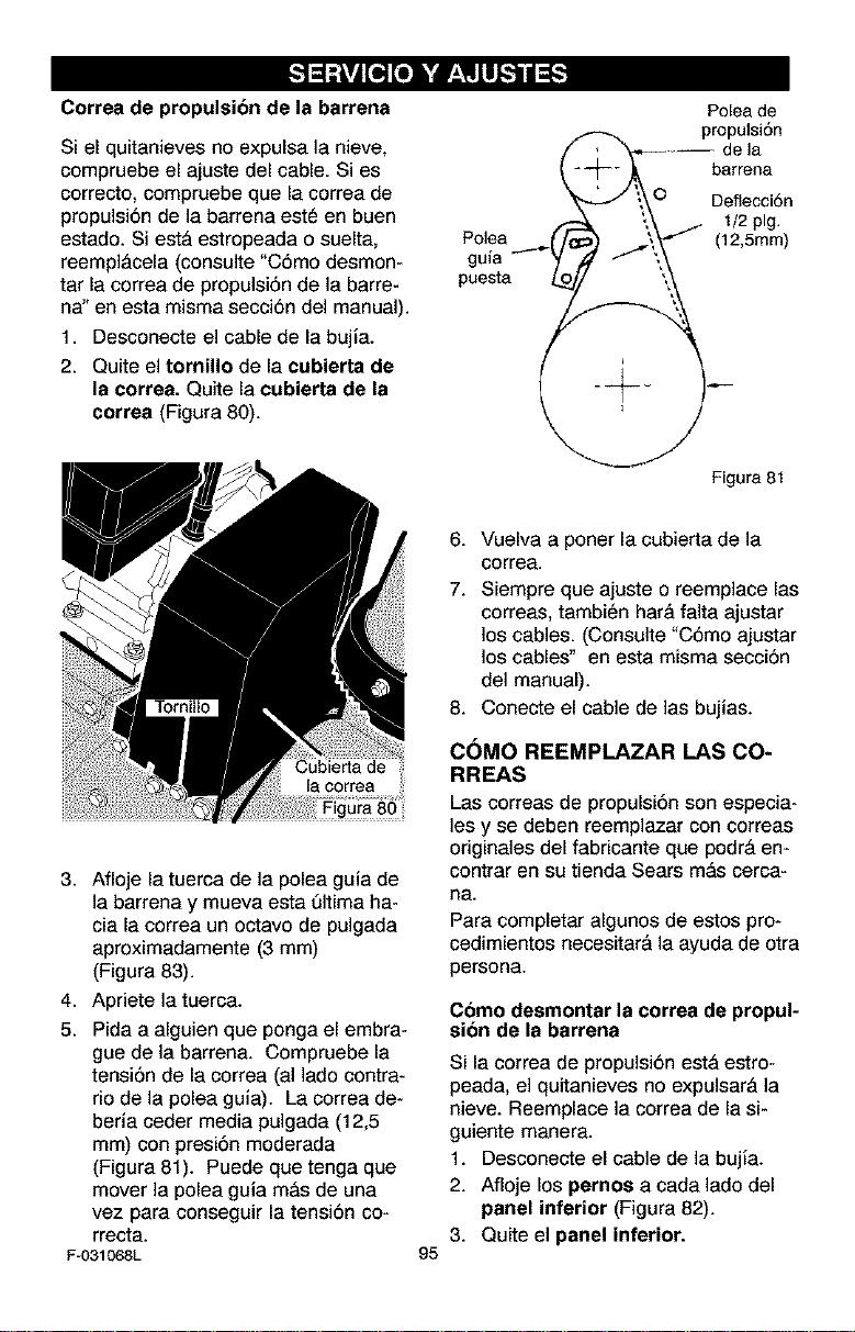
Correa de propulsion de la barrena
Si el quitanieves no expulsa la nieve,
compruebe el ajuste del cable. Si es
correcto, compruebe que la correa de
propulsi6n de la barrena est_ en buen
estado. Si est_ estropeada o suelta,
reempl_cela (consulte "C6mo desmon-
tar la correa de propulsi6n de la barre-
ha" en esta misma secci6n del manual).
1. Desconecte el cable de la bujia.
2. Quite el tornillo de la cubierta de
la correa. Quite la cubierta de la
correa (Figura 80).
Cubierta de
la correa
3. Afioje la tuerca de la polea guia de
]a barrena y mueva esta QItima ha-
cia la correa un octavo de pulgada
aproximadamente (3 mm)
(Figura 83).
4. Apriete la tuerca.
5. Pida a alguien que ponga el embra-
gue de la barren& Compruebe la
tensi6n de la correa (al lado contra-
rio de la polea guia). La correa de-
beria ceder media pulgada (12,5
mm) con presi6n moderada
(Figura 81). Puede que tenga que
mover la polea guia m&s de una
vez para conseguir la tensi6n co*
rrecta.
F-031068L
Poleade
_ propulsi6n
// "_--_-- de ]a
_ _-/_,., barrena
,/ ;\,O Deflecci6n
-'- ",\'-" /- 1/2 pig.
Polea (_ I',,\"_ (12,5mm)
puesta L.£//__,
Figura81
95
6. Vuelva a poner la cubierta de la
correa.
7. Siempre que ajuste o reemplace las
correas, tambien har& falta ajustar
los cables. (Consulte "C6mo ajustar
los cables" en esta misma secci6n
del manual).
8. Conecte el cable de las bujias.
C_MO REEMPLAZAR LAS CO-
RREAS
Las correas de propulsi6n son especia-
les y se deben reemplazar con correas
originales del fabricante que podr& en-
contrar en su tienda Sears m&s cerca-
ha.
Para completar algunos de estos pro*
cedimientos necesitar& la ayuda de otra
persona.
Como desmontar la correa de propul-
sion de la barrena
Si la correa de propulsi6n est& estro*
peada, el quitanieves no expulsar& la
nieve. Reemplace la correa de la si-
guiente manera.
1. Desconecte el cable de la bujia.
2. Afioje los pernos a cada lado del
panel inferior (Figura 82).
3. Quite el panel inferior.
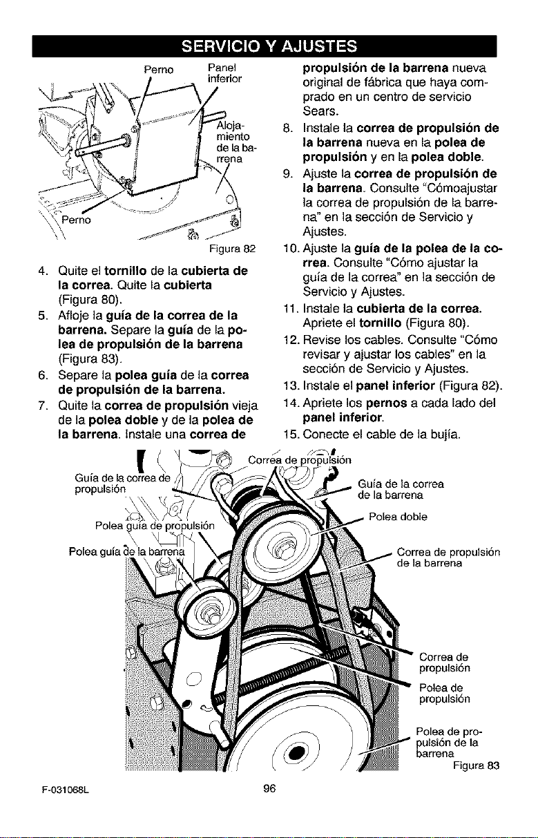
Pemo Panel
inferior
miento
de la ba-
Pemo
Figura 82
4. Quite el tornillo de la cubierte de
la correa. Quite la cubierte
(Figura 80).
5. Afloje la guia de la correa de la
barrena. Separe ]a guta de la po-
lea de propulsion de la barrena
(Figura 83).
6. Separe la polea guia de la correa
de propulsion de la barrena.
7. Quite la correa de propulsion vieja
de la pelea doble y de la polea de
la barrena, lnstale una correa de
Gula de lacorreade
propulsi6n
propulsibn de la barrena nueva
original de f&brica que haya com-
prado en un centre de servicio
Sears.
8. Instale la correa de propulsion de
la barrena nueva en la polea de
propulsi6n yen la pelea doble.
9. Ajuste la correa de propulsibn de
la barrena. Consulte "C6moajustar
la correa de propulsi6n de la barre-
ha" en la secci6n de Servicio y
Ajustes.
10. Ajuste la guia de la polea de la co-
rrea. Consulte "C6mo ajustar la
guia de la correa" en la secci6n de
Servicio y Ajustes.
11. Instale la cubierta de la correa.
Apriete el tornillo (Figura 80).
12. Revise los cables. Consulte "C6mo
revisar y ajustar los cables" en la
secci6n de Servicio y Ajustes.
13. InstaJe el panel inferior (Figura 82).
14. Apriete los pernes a cada lado del
panel inferior.
15. Conecte el cable de la bujia.
Correa de
Guia de la correa
Polea
Polea guia de la barrena
propulsi6n
de la barrena
F-031068L
96
Correa de
propulsi6n
Polea de
propulsi6n
Polea de pro-
pulsi6n de la
barrena
Figura 83
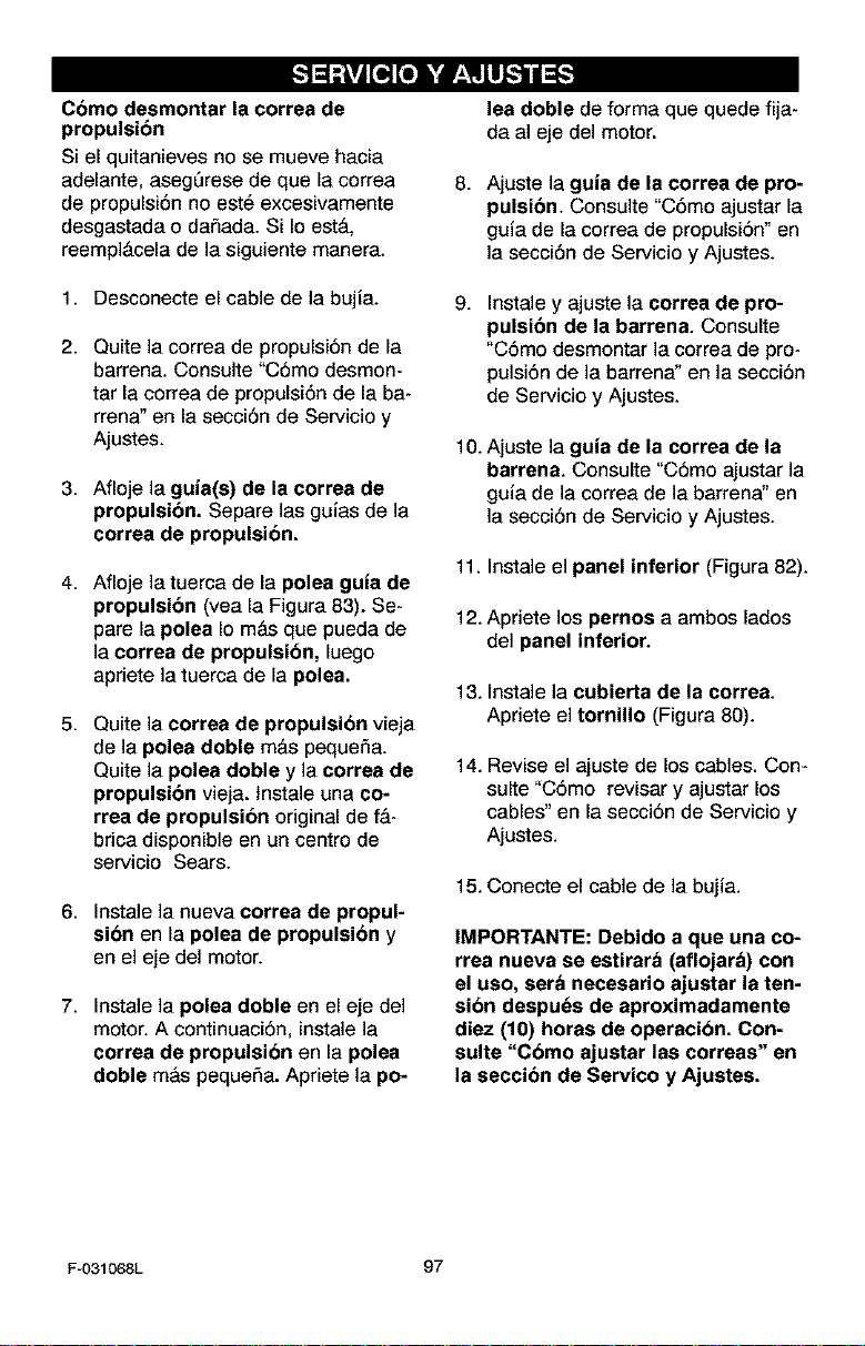
Come desmontar la correa de
propulsibn
Si el quitanieves no se mueve hacia
adelante, aseg_rese de que la correa
de propulsi6n no est_ excesivamente
desgastada o daSada. Si Io est&
reempl&cela de la siguiente manera.
1. Desconecte el cable de la bujia.
2. Quite la correa de propulsi6n de la
barrena. Consulte "C6mo desmon-
tar la correa de propulsi6n de la ba-
rrena" en la secci6n de Servicio y
Ajustes.
3. Afloje la guia(s) de la correa de
propulsibn. Separe las guias de la
correa de propulsion.
4. Afloje latuerca de la polea guta de
propulsion (yea la Figura 83). Se-
pare la polea Io m&s que pueda de
la correa de propulsion, luego
apriete la tuerca de la polea.
5. Quite la correa de propulsion vieja
de la polea doble m&s peque_a.
Quite la polea doble y la correa de
propulsion vieja, tnstale una co-
rrea de propulsion original de f_-
brica disponible en un centre de
servicio Sears.
6. Instale la nueva correa de propul-
sion en la polea de propulsion y
en el eje del motor.
7. Instale la polea doble en el eje del
motor. A continuaci6n, instale la
correa de propulsion en la pelee
doble m&s pequeSa. Apriete la po-
lea doble de forma que quede fija-
da al eje del motor.
8.
Ajuste la guia de la correa de pro-
pulsion. Consulte "C6mo ajustar la
guia de la correa de propulsi6n" en
la secci6n de Servicio y Ajustes.
9.
Instale y ajuste la correa de pro-
pulsibn de la barrena. Consulte
"C6mo desmontar la correa de pro-
pulsi6n de la barrena" en la secci6n
de Servicio y Ajustes.
10. Ajuste la guia de la correa de la
barrena. Consulte "C6mo ajustar la
guia de la correa de la barrena" en
la secci6n de Servicio y Ajustes.
11. Instale el panel inferior (Figura 82).
12. Apriete los pernos a ambos lades
del panel inferior.
13. Instale la cubierta de la correa.
Apriete el tornillo (Figura 80).
14.Revise el ajuste de los cables. Con-
suite "C6mo revisar y ajustar los
cables"en la secci6n de Servicio y
Ajustes.
15. Conecte el cable de la bujia.
IMPORTANTE: Debido a que una co-
rrea nueva se estirara (aflojara) con
el use, sera necesario ajustar la ten-
sion despu_s de aproximadamente
diez (10) horas de operacion. Con-
suite "Como ajustar las correas" en
la seccion de Servico y Ajustes.
F-O31068L 97
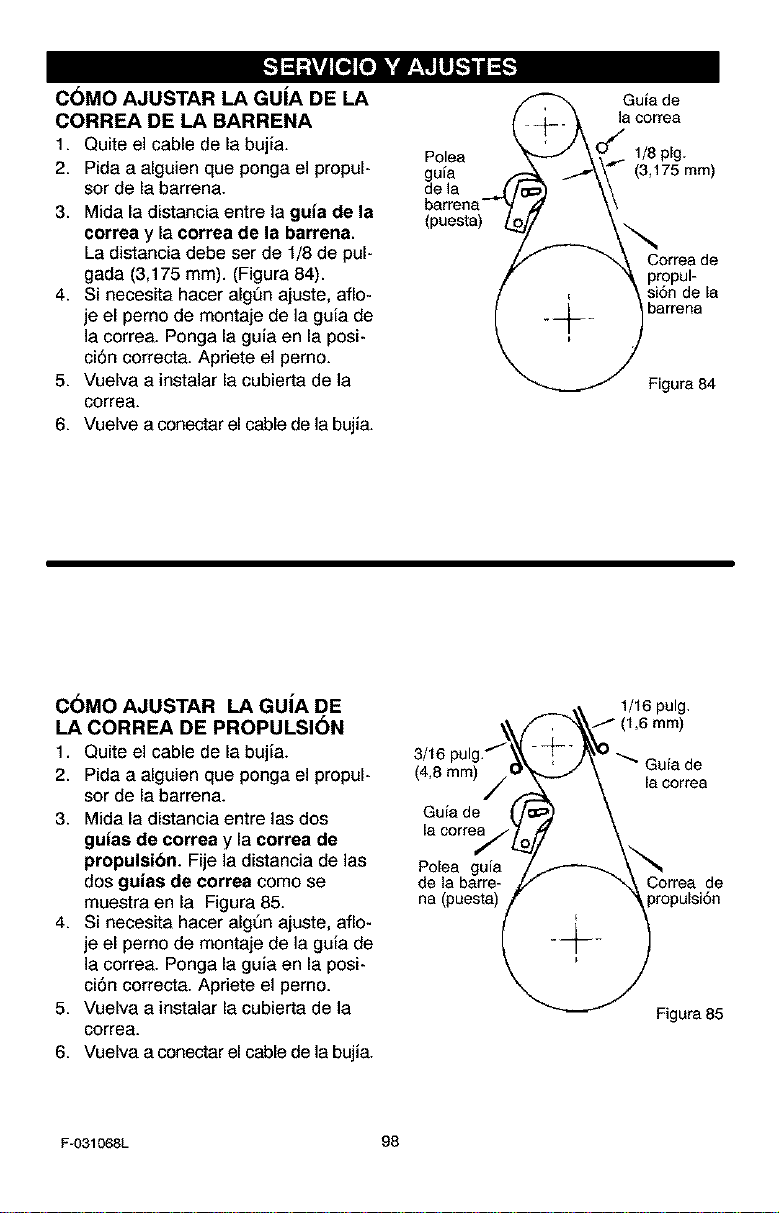
C6MO AJUSTAR LA GUiA DE LA
CORREA DE LA BARRENA
1. Quite el cable de la bujia.
2. Pida a alguien que ponga el propul-
sor de la barrena.
3. Mida la distancia entre la guta de la
correa y la correa de la barrena.
La distancia debe ser de 1/8 de pul-
gada (3,175 mm). (Figura 84).
4. Si necesita hacer algSn ajuste, aflo-
je el perno de montaje de la guia de
]a correa. Ponga la guia en la posi-
ci6n correcta. Apriete el pemo.
5. Vuelva a instalar la cubierta de la
correa.
6. Vuelve a conectar el cable de la bujia.
Polea
guia
de ]a
(puesta)
Guia de
la correa
1/Splg.
(3,175mm)
propul-
si6n de la
barrena
Figura84
C6MO AJUSTAR LA GUiA DE
LA CORREA DE PROPULSI6N
1. Quite el cable de la bujia.
2. Pida a alguien que ponga el propul-
sor de la barrena.
3. Mida la distancia entre las dos
gutas de correa y la correa de
propulsion. Fije la distancia de las
dos gutas de correa como se
muestra en la Figura 85.
4. Si necesita hacer alg_n ajuste, aflo-
je el perno de montaje de la guia de
]a correa. Ponga la guia en la posi-
ci6n correcta. Apriete el pemo.
5. Vuelva a instalar la cubierta de la
correa.
6. Vuelva a conectar el cable de la bujia.
3/16
(4,8mm)
Guia de
la correa
Polea guia
de la barre-
na (puesta)
1/16 pulg.
_ Guia de
la correa
de
propulsi6n
Figura 85
F-O31068L 98
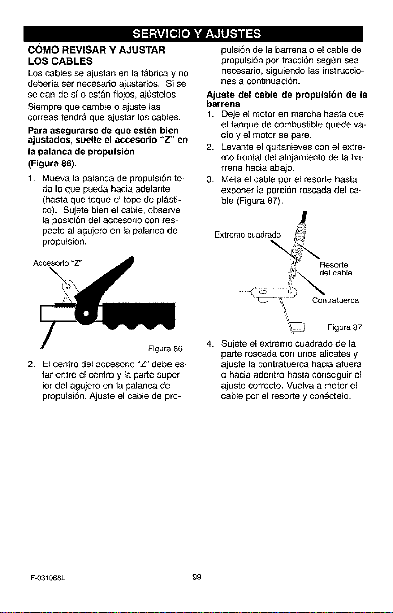
C6MO REVISAR Y AJUSTAR
LOS CABLES
Los cables se ajustan en la f&brica y no
deberia ser neeesario ajustarlos. Si se
se dan de si o est&n flojos, ajL_stelos.
Siempre que eatable o ajuste las
correas tendr& que ajustar los cables.
Para asegurarse de que estdn bien
ajustados, suelte el accesorio "Z" en
la palanca de propulsion
(Figura 86).
1. Mueva la palanca de propulsi6n to*
do Io que pueda hacia adelante
(hasta que toque el tope de pl&sti-
co). Sujete bien el cable, observe
la posici6n del accesorio con res-
pecto al agujero en la palanca de
propuisi6n.
Accesorio "Z"
pulsi6n de la barrena o el cable de
propulsi6n per tracci6n segQn sea
necesario, siguiendo las instruccio*
nes a continuaci6n.
Ajuste del cable de propulsibn de la
barrena
1. Deje el motor en marcha hasta que
el tanque de combustible quede va-
cioy el motor se pare.
2. Levante el quitanieves con el extre*
me frontal del alojamiento de la ba-
rrena hacia abajo.
3. Meta el cable por el resorte hasta
exporter ]a porci6n roscada del ca-
ble (Figura 87).
Extremo cuadrado
\
Resorte
del cable
Contratuerca
Figura 86
2. El centro del accesorio "Z" debe es-
tar entre el centro y la parte super-
ior del agujero en la palanca de
propulsi6n. Ajuste el cable de pro*
Figura 87
4. Sujete el extreme cuadrado de la
parte roscada con unos alicates y
ajuste la contratuerca hacia afuera
o hacia adentro hasta conseguir el
ajuste correcto. Vuelva a meter el
cable por el resorte y con_ctelo.
F-O31068L 99
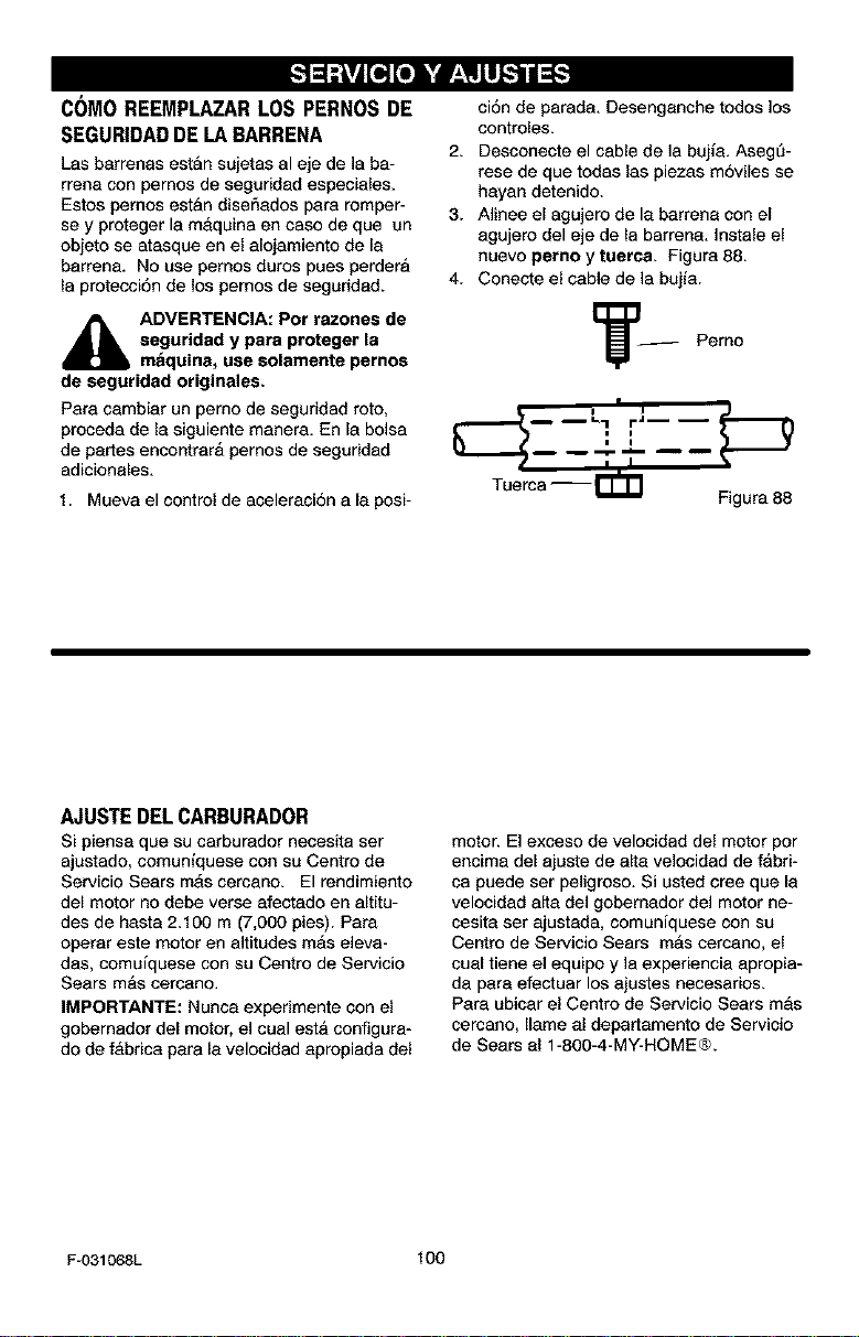
C(_MOREEMPLAZARLOSPERNOSDE
SEGURIDADDELABARRENA
Las barrenas est&n sujetas al eje de ]a ba-
rrena con pemos de seguridad especiales.
Estos pemos est&n diser_ados para romper-
se y proteger la m&quina en caso de que un
objeto se atasque en el alojamiento de la
barrena. No use pemos duros pues perder&
la protecci6n de los pemos de seguridad.
,_ ADVERTENCIA: Por razones de
seguridad y para proteger Is
maquina, use solamente pemos
de seguridad originales.
Para cambiar un pemo de seguridad roto,
proceda de la siguiente manera. En la bolsa
de partes encontrar& pemos de seguridad
adicionales.
1. Mueva el control de aceleraci6n a la posi-
ci6n de parada. Desenganche todos los
controles.
2. Desconecte el cable de la bujla. Aseg0-
rese de que todas las piezas m6viles se
hayan detenido.
3. Aiinee el agujero de la barrena con el
agujero del eje de la barrena. Instale el
nuevo pemo y tuerca. Figura 88.
4. Conecte el cable de la bujia.
Tuerca-- _=rhrl Figura 88
AJUSTE DEL CARBURADOR
Si piensa qua su carburador necesita ser
ajustado, somuniquese con su Centro de
Servisio Sears m&s cercano. El rendimiento
del motor no debe verse afectado en altitu-
des de hasta 2.100 m (7,000 pies). Para
operar este motor en altitudes m&s eleva-
das, comuiquese con su Centro de Servicio
Sears mas cercano.
IMPORTANTE: Nunca experimente con el
gobemador del motor, el cual est,, configura-
do de f&brica para la velocidad apropiada del
motor. El exceso de velocidad del motor por
encima del ajuste de alta velocidad de fabri-
ca puede ser peligroso. Si usted cree que la
velocidad aRa de] gobemador de] motor ne-
cesita ser ajustada, comunfquese con su
Centro de Servicio Sears mAs cercano, el
cuat tiene el equipo y la experiencia apropia-
da para efectuar los ajustes necesarios.
Para ubicar el Centro de Servicio Sears mas
cercano, Ilame al departamento de Servicio
de Sears al 1-800-4-MY-HOME®.
F-031068L 100
r;! ! tvil;Te] _ 1f;! tviII_ 1i I[I]
,_ ADVERTENCIA: Nunca guar-
de su quitanieves en am-
bientes interiores o en un
&rea cerrada y mal ventilada. Si
queda gasolina en el tanque, los va-
pores podrJan alcanzar alguna lla-
ma expuesta, chispa o llama piloto
de una caldera, calentador de
agua, secadora de ropa, cigarrillo,
etc.
Para prevenir el da_o (si el quitanieves
no se usa por m&s 30 dJas) prep&relo
como se indica a continuaci6n.
QUITANIEVES
1. Limpie todo el quitanieves.
2. Lubrique todos los puntos de lubri-
caci6n. Consulte la secci6n de Man-
tenimiento.
3. Aseg_rese de que todas las tuercas,
pernos y tornillos est_n bien apreta-
dos. lnspeccione todas las piezas
m6viles visibles para detectar da-
5os, roturas y desgaste. Haga los
reemplazos necesarios.
4. Retoque todas las superficies oxida-
das o que tengan la pintura saltada;
lijelas suavemente antes de aplicar
la pintura.
5. Cubra las piezas de metal expuesto
del soplador del alojamiento de la
barrena y del impulsor, con un anti-
corrosivo, tal como un lubricante en
aerosol.
NOTA: Una revisi6n o afinamiento
anual hecho en un Centro de Servicio
Sears es una buena manera de asegu-
rar que su quitanieves le brinde el m&-
ximo rendimiento la siguiente
temporada.
MOTOR
Deber& sacar la gasolina del tanque o
prepararla para prevenir la formaci6n
de dep6sitos de goma en el tanque, fil-
tro, manguera y carburador durante el
almacenamiento. Adem_s, durante el
almacenamiento, la gaso]ina mezclada
con alcohol que contiene etanol o me-
tanol (llamada a veces gasohol) atrae
agua, y _sta act6a sobre la gasolina
formando &cidos que daSan el motor.
1. Deje el motor en marcha hasta que
el tanque quede vacJo y el motor se
pare.
2. Si no quiere sacar la gasolina, use el
estabilizador de combustible provis-
to con la unidad, o compre estabili-
zador de combustible Craftsman
N6m. 3550. ASada el estabilizador
de combustible a cualquier cantidad
de gasolina que permanezca en el
tanque para minimizar los dep6sitos
de goma y &cido. Si el tanque est&
casi vacJo, mezcle el estabilizador
con gasolina fresca en un recipiente
separado y armadaun poco de esta
mezcla al tanque.
3. Siempre siga las instrucciones del
envase del estabilizador. Luego de
aSadir el estabilizador, encienda el
motor y dejelo correr por 10 minutos
por Io menos para permitir que la
mezcla alcance el carburador.
4. Cambie el aceite del motor
5. Lubrique el &rea del pist6n/cilindro.
Para hacerlo, saque primero la bujia
y coloque una gotas de aceite de
motor limpio en el z6calo de la bujia.
Luego cubra el z6calo con un patio
para absorber el exceso de aceite. A
continuaci6n, jale la manija de arran-
que manual unas dos o tres veces
para hacer girar el motor. Finalmen-
te, reinstale la bujia y conecte el ca-
ble.
OTRAS INDICACIONES
1. Si fuera posible, guarde su quita-
nieves dentro de un recinto, cubrien-
dolo para protegerlo del polvo y la
suciedad.
2. Si debe guardar el quitanieves afue-
ra, col6quelo sobre bloques para le-
vantarlo del suelo.
3. Cubra el quitanieves con una cubier-
ta protectora apropiada que no re-
tenga humedad. No use pl&stico.
IMPORTANTE: Nunca cubra el quita-
nieves mientras las _reas del motor y
del escape esten todavia calientes.
F-031068L 101
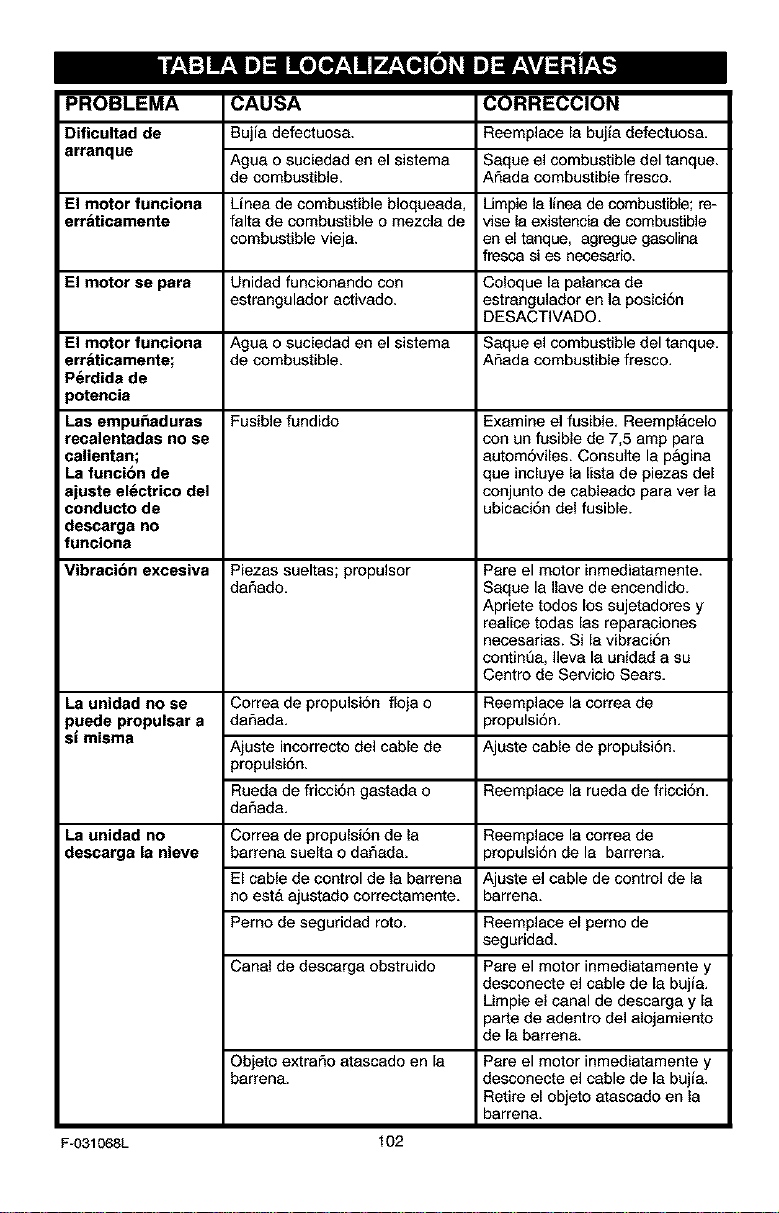
PROBLEMA
Dificultad de
arranque
CAUSA
Bujia defectuasa.
Ague o suciedad en el sistema
de combustible.
Linea de combustible bloqueada,
falta de combustible o mezcla de
combustible vieja.
CORRECCION
Reemplacela bujia defectuosa,
Saque el combustible del tanque.
Armadacombustible fresco.
El motor funciona Umple ]a linea de combustible; re-
err&ticamente vise le existencia de combustible
en el tanque, agregue gasoline
fresca si es necesarle.
El motor se para Unidad funcionando con Coloque la palanca de
estrangulador activado, estrangulador en la posici6n
DESACTIVADO.
El motor funciona Ague o suciedad en el sistema Saque e] combustible (]el tanque.
err&ticamente; de combustible. Armadacombustible fresco.
P_rdida de
)otencia
Las empu_aduras Fusible fundido Examine el fusible. Reempl_cele
recalentadas no se con un fusible de 7,5 amp para
calientan; autom6viles. Consulte la pagina
La funcibn de que incluye la lista de piezas del
ajuste el_ctrico del conjunto de cableado pare vet la
conducto de ubicaci6n del fusible.
descarga no
funciona
Vibracibn excesiva Piezas sueltas; propulsor Pare el motor inmediatamente.
dafiado. Saque la Ilave de encendido.
Apriete todos los sujetadores y
realice todas [as reparaciones
necesarias. Si la vibraci6n
continua, ]]eva la unidad a su
Centro de Servicio Sears.
La unidad no se Correa de propulsi6n fleja o Reemplace la correa de
puede propulsar a dafiada, propulsi6n.
sl misma
Ajuste incorrecto del cable de Ajuste cable de propulsi6n.
propulei6n.
Rueda de fricci6n gastada o Reemplace la rueda de fricci6n.
dafiada.
La unidad no Correa de propulsi6n de la Reemplace la correa de
descarga la nieve barrena suelta o daSada, propulsi6n de la barrena.
El cable de control de la barrena Ajuste e] cable de control de la
no est& ajustado correctamente, barrena.
Pemo de seguridad roto. Reemplace el perno de
seguridad.
Canal de descarga obstruido Pare el motor inmediatamente y
desconecte e] cable de la bujia.
Limpie el canal de descarga y la
parte de adentro del alojamiento
de la barrena.
Objeto extrar_o atascado en la
barrena.
Pare el motor inmediatamente y
desconecte el cable de la bujia.
Retire el objeto atascado en la
barrena.
Fu031068L 102
SEARS, ROEBUCK AND CO.
Garantia limitada de cumplimiento con el Sistema Federal
de control de emisiones y con el sistema de control de
emisiones del Estado de California
Motores pequef_os para vehiculos todo terreno
CONTROL DE EMISIONES DE
CALIFORNIA Y DE LA AGENCIA DE
PROTECCI(_N AMBIENTAL (EPA) DE
E,U,A, - DECLARACI(_N DE LA
GARANTiA
La Agencia de Protecci6n Ambiental de los
Estados Unidos ("EPA"), el Consejo de Cali-
fornia para los Recursos del Aire ("CARB") y
Sears, Roebuck and Co. tienen el placer de
explicar Io que es la Garantia Federal y de Ca-
lifornia para Sistemas de Control de Emisio-
nes de su nuevo motor pequeSo para
vehiculos todo terreno. En California, los mo-
tores peqoeSos para vehiculos todo terreno
de medelo 1995 y medelos de aSos posterio-
res deben ser diseSados, construidos y equi-
pados para cumplir con las estrictas normas
anti contaminaci6n del Estado. En otros esta-
dos, los motores medelo 1997 y modelos de
aSos posteriores deben estar diseSados,
construidos y equipados, al momento de su
venta, para que cumplan con Ins disposicio-
nes de la EPA acerca de motores pequeSos
para vehiculos tedo terreno. Sears, Roebuck
and Co., garantizara el sistema para el control
de emisiones de su motor peqoeSo para vehi-
culos todo terreno por los periedos de tiempo
qoe se mencionan mas adelante, siempre y
cuando su motor pequeSo para vehiculos todo
terreno no haya sufedo alg5n abuso, negligen-
cia, medificaci6n no aprobada o mantenimien-
to indebido.
Su sistema para el control de emisiones puede
incluir partes como el carburador, el sistema
de encendido y el sistema de escape. Tambi6n
puede incluir el sistema de descompresi6n y
otras unidades relacionadas con las emisio-
nes.
Cuando surja una condici6n protegida per la
garantia, Sears, Roebuck and Co., reparara
su motor pequer_o para vehiculos tedo terreno
sin costo alguno para usted per concepto de
diagn6stico, partes y mano de obra.
SISTEMA PARA EL CONTROL DE
EMISIONES DEL FABRICANTE -
COBERTURA DE LA GARANTIA
Los sistemas para el control de emisiones del
modelo 1995 y modelos de aSos posteriores
de motores peqoeSos para vehiculos todo te-
rreno en California estAn garantizados pot dos
aSos, tal y como se menciona en la presente
garantia. En otros estados, los motores mode-
Io 1997 y modelos de aSos posteriores tam-
bi_n est&n garantizados pot dos aSos. En
caso de que, durante dicho periodo de la ga-
rantia, cualquier pieza del motor, relacionada
con emisiones est_ defectuosa en sos mate-
riales o mano de obra, Sears, Roebuck and
Co., reparara o cambiarA dicha pieza.
RESPONSABILIDADES DEL
PROPIETARIO DE LA GARANTJA
Come propietario del motor pequeSo para ve-
hiculos todo terreno usted es responsable de
qoe se Ileve a cabo el mantenimiento reqoeri-
do que se menciona en el Manual del uscario,
pero Sears, Roebuck and Co., no negar& la
garantia _nicamente debido a lafalta de un re-
cibo o a que usted no proporcione una prueba
escrita de que se ha Ilevado a cabo el manteni-
miento programado.
No obstante, usted, come propietario del mo-
tor pequeSo para vehiculos todo terreno, de-
bet& estar consciente de que Sears, Roebuck
and Co., le poede negar la cobertura de la ga-
rantia si su motor o alguna parte del mismo ha
fallado debido a abuso, negligencia, manteni-
miento inadecuado o medificaciones no apro-
badas.
Usted es responsable de presentar su motor
pequeSo para vehiculos tedo terreno en elTa-
ller de Servicio Autorizado de Sears, Roebuck
and Co., en cuanto surja el problema. Las re-
paraciones bajo la garantia deben Ilevarse a
cabo dentro de un periodo de tiempo razona-
ble que no exceda de 30 dias.
Se puede programar el servicio de garantia
Ilamando al Taller de Servicio Autorizado de
F-031068L 103
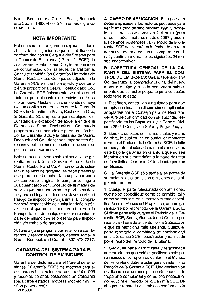
Sears, Roebuck and Co., o a Sears, Roebuck
and Co., al 1-800-473-7247 (llamada gratui-
taen E.U.A.).
NOTA IMPORTANTE
Esta declaraci6n de garantfa explica los dera-
chos y las obligaaleaes que usted tiene de
conform]dad con la Garantia del Sistema pare
el Control de Emisiones ("Garantfa SCE"), le
cual Sears, Roebuck and Co., le proporcieaa
de confermidad con las ]eyes de California.
Consulte tambi_n las Garantias Limitadas de
Sears, Roebuck and Co., que se adjuntan ala
Garantfa SCE en una hoja aparte y que tam-
bi6n le proporciona Sears, Roebuck and Co.,
La Garantfa SCE Qnicamente se aplica en el
sistema para el control de emisiones de su
motor nuevo. Haste el punto en donde no haya
alng,_n conflicto en t6rminos entre la Garantia
SCE y la Garantfa de Sears, Roebuck and Co.,
la Garantfe SCE aplicara pare cualquier cir-
cunstancia a excepci6n de aquella an qoe le
Garantfa de Sears, Roebuck and Co., puede
proporcionar un periodo de garantfa mAs lar-
go. Le Garantfa SCE y la Garantfa de Sears,
Roebuck and Co., describen importantes de-
rechos y obligaciones que usted tiene con res-
pacto a su motor nuevo.
S61o se puede Ilever a cabo el servicio de ge-
rantfe en un Taller de Servicio Autorizado de
Sears, Roebuck and Co. AI momenta de sol]ci-
ter un servicio de garantfa, se debe presenter
una prueba de la fecha de cempre par parta
del comprador original. El comprador pagara
cuelquier cargo per concepto de Ilamadas de
servialo y/o transportaci6n de productos des-
de y pare el lugar en donde se Ileve a cabo el
trebajo de inspecci6n y/o garantfa. El compra-
dor set& respensable de cualquier dermao p_r-
dida an el qua se incurra con relaci6n a la
transportaci6n de cualquier motor o cualqaler
parte del mismo qua se prasente pare inspec-
al6n y/o trabajo de garentfe.
Si tiene alguna pregunte con ralaci6n e sus de-
rachos y responsabilidades, debera Ilamar e
Sears, Roebuck end Co., el 1-800-473-7247.
GARANTiA DEL SISTEMA PARA EL
CONTROL DE EMISIONES
Garantfa de] Sistema pare el Control de Emi-
siones CGarantfa SCE") de motores peque-
5as pare vehfculos todo terreno modelo 1995
y modelos de aSos poster]ores en California
(para otros estados, motores modelo 1997 y
arias posteriores):
F-031068L 104
A. CAMPO DE APLICACI(3N: Esta garantfa
deberA aplicarse a los motores paquefios para
vehfculos todo terreno modelo 1995 y mode-
los de aSos posteriores en California (para
otros estados, motoras modelo 1997 y mode-
los de ar_os poster]ores). El Per]ode de ]a Ge-
rentfa SCE se ialalara en la fecha de entrega
del nuevo motor o equipo al comprador origi-
nal y continuar& durante los siguientes 24 me-
ses consecutivos.
B. COBERTURA GENERAL DE LA GA-
RANTiA DEL SISTEMA PARA EL CON-
TROL DE EMISIONES: Sears, Roebuck and
Co. garantfza al comprador original del nuevo
motor o equipa y a cada comprador subse-
cuente que su motor pequer_o pare vehicalos
tado terreno esta:
1. Disefiado, construido y eqalpado pare que
cumpla con todas las disposiciones aplicables
adoptedas per el Consajo para los Recursos
del Aire de conform]dad con su autoridad es-
pacificada an los Capftulos 1 y 2, Parte 5, Divi-
si6n 26 del CSdigo de Salud y Seguridad, y
2. Libre de defestos en sus matedales y mane
de obra, Io cual cause en cualquier momenta
durante el Pedodo de la Garantfa SCE, la falla
de una parte relacionada con emisieaes y que
est6 bajo la garantfa en cuanto a que no sea
id6ntica en sus materieles ale parte descrita
en la solicitud de motor del fabricante pare su
certificaci6n,
C. La Garantfa SCE s61oataSe alas partes de
su motor relacionadas con emisiones de la si-
guiente manera:
1. Cualquier parte relaalonada con emisiones
que no se especifique coma de cembio, tal y
come se requiere en el mantenimiento especi-
ficado en el Manual dal Propietario, deberA ga-
rantizarse par el Periodo de la Garantfa SCE.
Si dicha parte falla dorante el Periodo de la Ga-
rantfa SCE, Sears, Roebuck and Co. la repa-
tar& o cambiarA de acuerdo con la Subsecci6n
4 qoe se menciona mas adelante. Cualquier
parte reparade o cambiada de conformidad
con la Garantfa SCE debera ester garantizada
par el testa del Periodo de le misma.
2. Cualquier parte garantizada y relacionada
con emisiones que est_ especificada s6]o pa-
re inspacalones regulates conforme al Manual
del Propieterio debera estar garantizade par el
Periodo de la Garantia SCE. Una dealarani6n
en dichas instrucciones per escdto a efecto de
"reparar o cambiar tel y coma sea neceserio"
no redualra el Periodo de la Garantfa SCE. Di-
che parte repareda o cambieda conforme ala
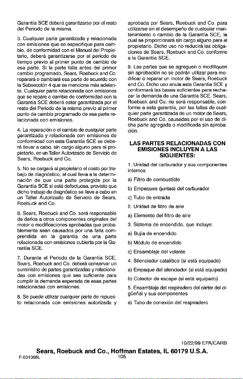
GarantiaSCEdeberAgarantizarseperelresto
delPeriododelemisme.
3.Cualquierpartegarantizadayrelacionada
conemisiones que se especifique pare cam-
bio, de conformidad con el Manual del Propie-
tario, debar& garantizarse per el periodo de
tiempo previo al primer punto de cambio de
esa perte. Si ]a parte falla antes del primer
cambio progremado, Sears, Roebuck and Co.
repararA o cambiarA esa parte de acuerdo con
la Subsecci6n 4 qua se menciona mas adelan-
te. Cualquier parte relacionada con emisiones
que se repere o cambie de conformidad con la
Garantia SCE deberA ester garantizada par el
resto del Periodo de le misma previo al primer
punto de cambio programado de esa parte re-
lacionada con emisiones.
4. La reparaci6n o el cambio de cualquier pare
garantizada y relacionada con emisiones de
conformided con esta Garantia SCE se debe-
r& Ilevar a cabo, sin cargo alguno pare el pro-
pietario, en unTaller Autarizado de Servicio de
Sears, Roebuck and Co.
5. No se cargarA al propietario el costo par tra-
bajo de diagn6stico, el cual Ileva ale determi-
naci6n de qua une parte protegida per la
Garantia SCE si estA defectuosa, provisto que
dicho trabajo de diagn6stico se ]lave a cabo en
un Taller Autorizado de Servicio de Sears,
Roebuck and Co.
6. Sears, Roebuck and Co. sara responsable
de daSos e otros componentes originales del
motor o modificaciones aprobades que probe-
blemente sean causados par una falla com-
prendida en la garantia de una parte
relacionada con emisiones cubierta par ]a Ga-
rantia SCE.
7. Durente el Periodo de la Garantia SCE,
Sears, Roebuck and Co. debera conserver un
suministro de partes garantizadas y releciona-
des con emisiones qua sea suficiente pare
cumplir la demanda esperada de esas partes
relacionadas con emisiones.
8. Se puede utilizer cualquier parte de repues-
to relacionada con emisiones aetorizada y
aprobada per Sears, Roebuck and Co. pare
utilizarse en el desempeSo de cualquier man-
tenimiento o cambio de la Garantia SCE, le
cuel se proporcionar& sin cargo alguno para el
propietario. Dicho use no reducirA Ins oblige-
clones de Sears, Roebuck and Co. conforme
ala Garantla SCE.
9. Las partes que se agreguen o modifiquen
sin aprobaci6n no se podrAn utilizer pare mo-
dificar o reparar un motor de Sears, Roebuck
and Co. Dicho use anula esta Garentia SCE y
conformer& Ins bases suficientes pare recha-
zar la demanda de una Garantia SCE. Sears,
Roebuck and Co. no sere responsable, con-
forme a esta garantia, par las fallas de cual-
quier parte garantizada de un motor de Sears,
Roebuck end Co. causadas par el use de di-
che parte agregada o modificada sin aproba-
ei6n.
LAS PARTES RELACIONADAS CON
EMISIONES INCLUYEN A LAS
SIGUlENTES:
t, Unidad del carburador y sus componentes
internes
e) Filtre de combustible
b) Empaques (juntas) del carburader
c) Tubo de entreda
2, Unidad de filtre de aire
e) Elemento del filtre de aire
3, Sistema de encendido, que incluye:
e) Bujia de encendide
b) M6dulo de encendide
c) Ensamblaje del velante
4, Silenciader catalltice (si esta equipade)
e) Empaque del silenciader (siesta equipado)
b) Celeeter de escape (si esta equipade)
5, Ensembleje del respiradero del c&rter del ci-
gL_efialy sus componentes
e) Tubo de conexi6n del respiradero
10/22/99 EPA/CARB
Sears, Roebuck and Co., Roffman Estates, IL 60179 U.S.A.
F-031068L 105

F-O31068L 106

F_O31068L 107

Your Home
©Sears, Rcebuck and Co.
TM SM
® Registered Trademark / Trademark / Service Mark of Sears, Roebuck and Co.
TM SM
® Marca Registrada / Marca de F_bdca / Marca de Servicio de Sears, Roebuck and Co.
MC MD
Marque de commerce / Marque d6posee de Sears, Roebuck and Co.