Loading ...
Loading ...
Loading ...
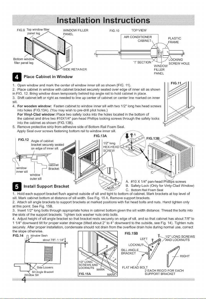
FIG.9 Top window filler WINDOW FILLER
panel leg PANEL
d
U
filler panel leg
;IDE RETAINER
_ Place Cabinet in Window
1. Open window and mark the center of window inner sill as shown (FIG. 11).
2. Place cabinet in window with cabinet bracket securely seated over edge of inner sill as shown
in FIG. 12. Bring window down temporarily behind top angle rail to hold cabinet in place.
3. Shift cabinet left or right as needed to line up center of cabinet on center line marked on inner
sill.
4. For wooden window: Fasten cabinet to window inner sill with two 1/2" long hex head screws
into holes (FIG.13A). (You may wish to pre-drill pilot holes.)
For Vinyl-Clad window: Place two safety locks into the holes located in the bottom of
the cabinet and drive two #10Xl/4" pan-head Phillips locking screws through the safety locks
into the cabinet as shown (FIG.13B).
5. Remove protective strip from adhesive side of Bottom Rail Foam Seal.
Apply Seal over screws fastening bottom rail to window inner sill. ...................
FIG.12 Angle of cabinet
bracket securely seated
on edge of inner sill.
_net
window I F -J Bracket
inner sill I I
window i
outer sill
13
install Support Bracket
FIG.10 TOP VIEW
_ AIR CONDITIONER ] PLASTIC
'_ I I J LOCKING
"1"SECTION _ _ SCREW HOLE
WINDOW
FILLER
PANEL
1. Hold each support bracket flush against outside of sill and tight to bottom of cabinet. Mark brackets at top level of
sill. Mark cabinet bottom at distance of sill width. See Fig. 15 A. Remove support brackets.
2. Attach sill angle brackets to support brackets at marked positions with flat head bolts and nuts. Hand tighten only
at this point. See Fig. 15B.
3. Insert 1/2" long bolts through appropriate holes in cabinet bottom given the sill width distance. Thread the bolts into
the slots of the support brackets. Tighten lock washer nuts onto bolts.
4. Adjust height of sill angle bracket so that bracket rests securely on edge of sill, and so that cabinet has about 7/8" to
1 1/4" downward tilt for proper water drainage (tilted about 2° to 4° downward to the outside, see Fig. 14). Tighten nuts
securely. After proper installation, condensate should not drain from the overflow drain hole during normal use, correct
the slope otherwise.
FIG.14 [7,/Window Sash
i about 7/8"- 1 1/4'q,
L---] _Side L......
Sill Ang}e Bracket
Window Sill
FIG.15A MAF_';_
FIG.15B
T-_._ 1/2" LONG SCREWS
LEy _ _AND LOCKNUTS
Si L L :NO:LKENUT_'d_//
BRACKET 71 [_// FRIGHT
FLAT HEA_OL
2 EACH REQ'D FOR EACH
SUPPORT BRACKET
Loading ...
Loading ...
Loading ...