
OPERATION AND INSTALLATION
OPERACIÓN E INSTALACIÓN
UTILISATION ET INSTALLATION
Tankless Electric Water Heater
Calentador de Agua Instantáneos sin Tanque
Chauffe-Eau Électrique sans Accumulateur
»DHC 3-1
»DHC 3-2
»DHC 4-2
»DHC 4-3
»DHC 5-2
»DHC 6-2
»DHC 8-2
»DHC 9-3
»DHC 10-2
Certified to ANSI/UL Std. 499
Conforms to CAN/CSA Std. E335-1 & E335-2-35
Certificación con ANSI/UL Std. 499
Conforme a CAN/CSA Std. E335-1 & E335-2-35
Certifié à la norme ANSI/UL Std. 499
Conforme à la norme CAN/CSA Std. E335-1 & E335-2-35
Tested and certified by WQA to NSF/ANSI372
for lead free compliance.
Probado y certificado por WQA NSF/ANSI 372 para
el cumplimiento de las regulaciones sin plomo.
Testé et certifié par WQA à la NSF/ANSI 372 pour une
utilisation sans plomb.
2 | DHC WWW.STIEBEL-ELTRON-USA.COM
CONTENTS | OPERATION
OPERATION
1. General information
Note
Read these instructions carefully before using the ap-
pliance and familiarize yourself with its functions. Keep
these instructions safe. Pass on the instructions to a new
user if required.
1.1 Safety information
1.1.1 Structure of safety information
KEYWORD Type of risk
Here, possible consequences are listed that may re-
sult from not observing the safety information.
f Steps to prevent the risk are listed.
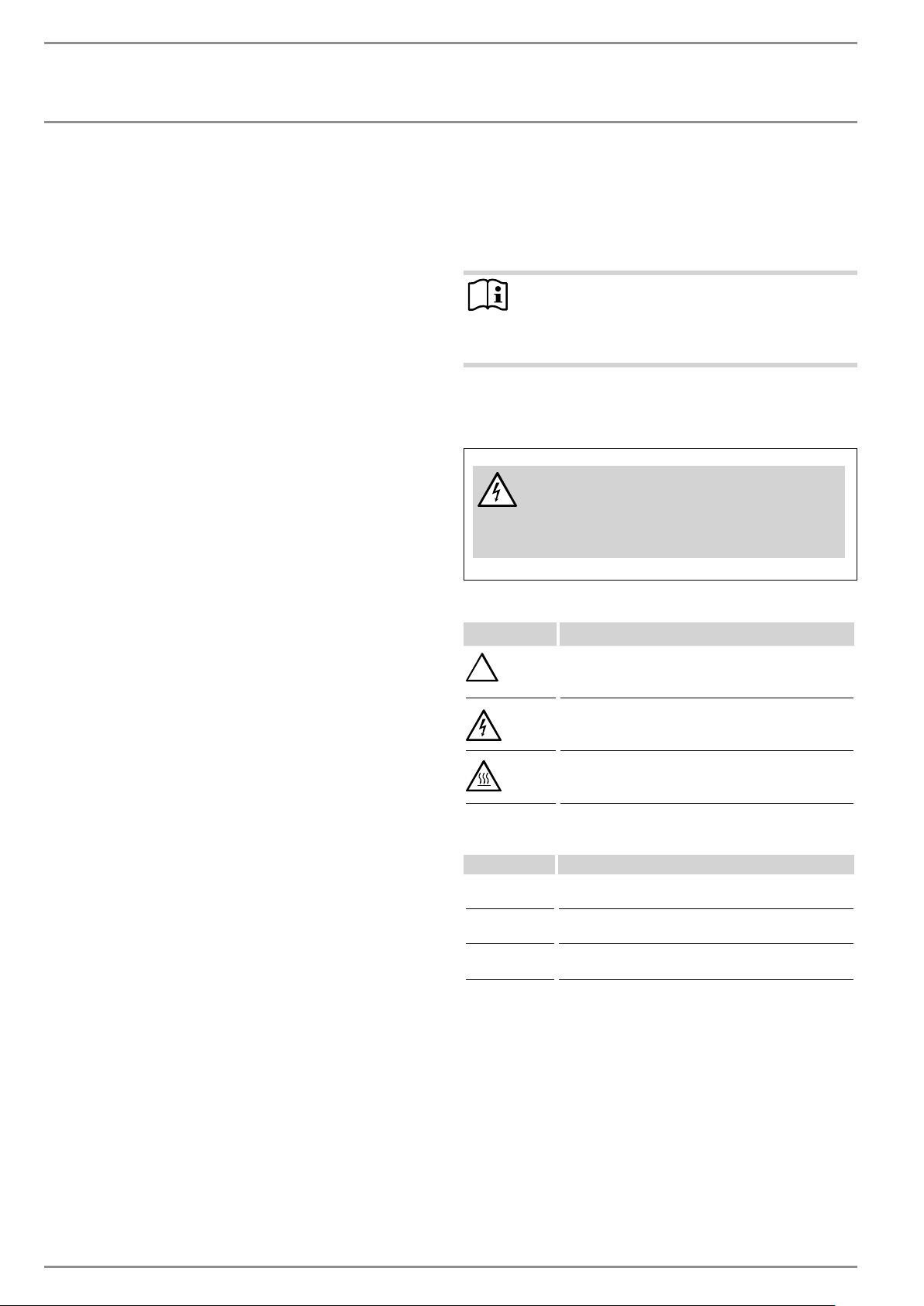
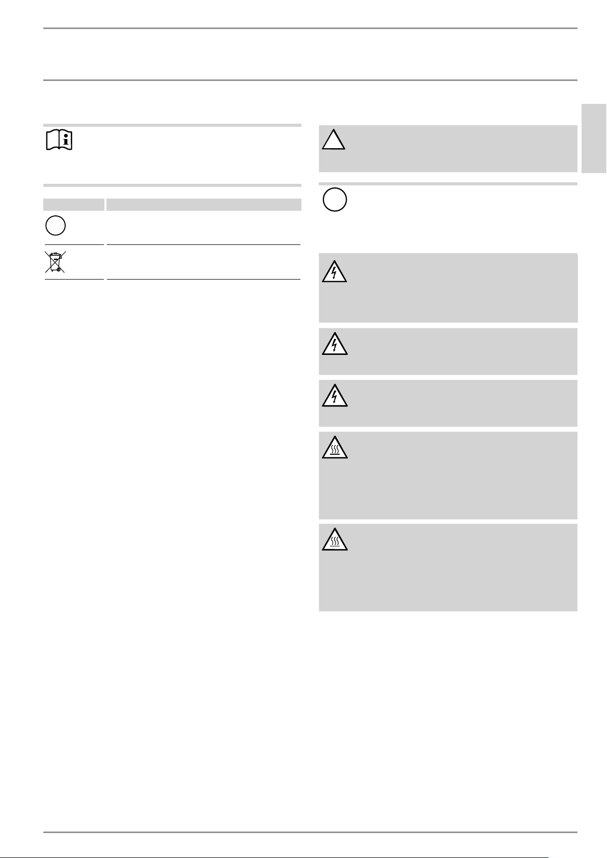
1.1.2 Symbols. type of risk
Symbol Type of risk
!
Injury
Electrocution
Burns or scalding
1.1.3 Keywords
KEYWORD Description
DANGER If this information is not observed, it will result in serious
injury or death.
WARNING If this information is not observed, it can result in serious
injury or death.
CAUTION If this information is not observed, it can lead to medium
or minor injury.
OPERATION
1. General information _________________________________________2
1.1 Safety information _______________________________________________ 2
1.2 Other symbols in this document ______________________________ 3
2. Safety __________________________________________________________3
2.1 Intended use ______________________________________________________ 3
2.2 General Information_____________________________________________ 3
2.3 Safety Precautions _______________________________________________ 3
2.4 Test symbols ______________________________________________________ 3
3. Register your product _______________________________________4
4. General ________________________________________________________4
INSTALLATION
5. Mounting the unit ____________________________________________4
6. Water connections ___________________________________________5
7. Electrical connection _________________________________________5
7.1 Terminal block ____________________________________________________ 6
8. Commissioning _______________________________________________6
8.1 Appliance handover _____________________________________________ 6
9. Troubleshooting ______________________________________________7
10. Normal maintenance _________________________________________8
11. Technical Data ________________________________________________8
11.1 Dimensions ________________________________________________________ 8
11.2 Wiring diagram __________________________________________________ 8
11.3 Temperature increase above ambient water temperature
______________________________________________________________________ 9
11.4 Data table ________________________________________________________ 10
12. Spare parts _________________________________________________ 11
13. Warranty ____________________________________________________ 12
OPERATION
SAFETY
ENGLISH
WWW.STIEBEL-ELTRON-USA.COM DHC | 3
1.2 Other symbols in this document
Note
Notes are bordered by horizontal lines above and below
the text. General information is identified by the symbol
shown on the left.
f Read these notes carefully.
Symbol
!
Damage to the appliance and environment
Appliance disposal
f This symbol indicates that you have to do something. The ac-
tion you need to take is described step by step.
2. Safety
Observe the following safety information and regulations.
Operate the appliance only when fully installed and with all safety
equipment fitted.
2.1 Intended use
The appliance is intended for heating domestic hot water and can
supply one draw-off point.
Any other use beyond that described shall be deemed inappro-
priate.
Observation of these instructions is also part of the correct use
of this appliance.
2.2 General Information
This appliance is designed for domestic use. It can be used safely
by untrained persons. The appliance can also be used in a non-
domestic environment, e.g. in a small business, as long as it is
used in the same way.
Read this entire manual. Failure to follow all the guides, instruc-
tions and rules could cause personal injury or property damage.
Improper installation, adjustment, alteration, service and use of
this appliance can result in serious injury.
This appliance must be installed by a licensed electrician and
plumber. The installation must comply with all national, state and
local plumbing and electric codes. Proper installation is the re-
sponsibility of the installer. Failure to comply with the installation
and operating instructions or improper use voids the warranty.
Save these instructions for future reference. Installer should leave
these instructions with the consumer.
If you have any questions regarding the installation, use or opera-
tion of this water heater, or if you need any additional installation
manuals, please call our technical service line, see last side.
2.3 Safety Precautions
!
DANGER: Injury
Please read and follow these instructions. Failure to
follow these instructions could result in serious per-
sonal injury or death.
!
Damage to the appliance and the environment
The appliance must be installed by a licensed electri-
cian and plumber. The installation must comply with all
national, state and local plumbing and electric codes.
Service of the appliance must be performed by qualified
service TECHNICIANS.
DANGER: Electrocution
Before proceeding with any installation, adjustment.
Alteration, or service of this appliance all circuit
breakers and disconnect switches servicing the appli-
ance must be turned off. Failure to do so could result
in serious personal injury or death.
DANGER: Electrocution
Never remove the appliance‘s cover unless the elec-
tricity servicing the appliance is turned off. Failure to
do so could result in personal injury or death.
DANGER: Electrocution
The appliance must be properly grounded. Failure to
electrically ground the product could result in serious
personal injury or death.
DANGER: Burns
Water temperatures over 125°F (52 °C)can cause
severe burns instantly or death from scalding. A hot
water scalding potential exists if the thermostat on
the appliance is set too high. Households with small
children, disabled or elderly persons may require that
the thermostat be set at 113°F (45 °C) or lower to
prevent possible injury from hot water.
WARNING: Injury
Where children or persons with limited physical, sen-
sory or mental capabilities are to be allowed to con-
trol this appliance, ensure that this will only happen
under supervision or after appropriate instructions by
a person responsible for their safety. Children should
be supervised to ensure that they never play with the
appliance.
2.4 Test symbols
See type plate on the appliance.
4 | DHC WWW.STIEBEL-ELTRON-USA.COM
INSTALLATION
REGISTER YOUR PRODUCT
3. Register your product
You must register this product within 90 days of pur-
chase on our web site in order to activate the standard
warranty or to be eligible for the extended warranty.
Go to our web site at www.stiebel-eltron-usa.com
and click on register your product.
Before beginning the registration process, we suggest that
you gather the necessary information which will be as
follows:
Type, Example: DHC (from the label that is on the unit)
Number listed after "Nr."
Place of Purchase
Purchase Date
First & Last Name
Email address
Physical Address
Phone Number
Installation Date
IF YOU HAVE ANY QUESTIONS CONCERNING THE REGISTRA-
TION PROCESS OR WARRANTY OPTIONS, PLEASE CONTACT
STIEBEL ELTRON USA DIRECTLY AT (800)-582-8423.
4. General
The DHC tankless water heater differs from conventional storage
type water heaters in several ways. It does not store hot water.
Instead, water is heated instantaneously as it flows through the
unit. The powerful heating elements are activated by a flow switch
as water is drawn from a hot water faucet connected to the DHC.
Due to the absence of stand-by losses, the DHC has greater energy
efficiency than storage type water heaters.
The temperature of the hot water delivered by the DHC depends
on the wattage of the heating element, the temperature of the
incoming cold water, and the water flow rate through the unit.
In order for the DHC to operate properly, it must be carefully
matched to the application.
In case you have questions regarding the way you plan to use the
DHC, please call our technical service line at 800-582-8423 (USA and
Canada). For service outside the U.S. and Canada, please call us at
USA 413-247-3380. You can also e-mail us at info@stiebel-eltron-
usa.com or fax us at 413-247-3369.
The DHC can be used for hand washing type applications in the
U.S. and Canada:
- Restroom sinks in commercial/industrial facilities and homes
- Kitchen areas in commercial /industrial facilities and homes
-Cabins
- Special uses in photo developing shops, laboratories etc.
The DHC can also be used for whole apartments and homes in
warm climate zones such as the Caribbean region, Central Amer-
ica and Mexico due to the higher ambient water temperatures.
INSTALLATION
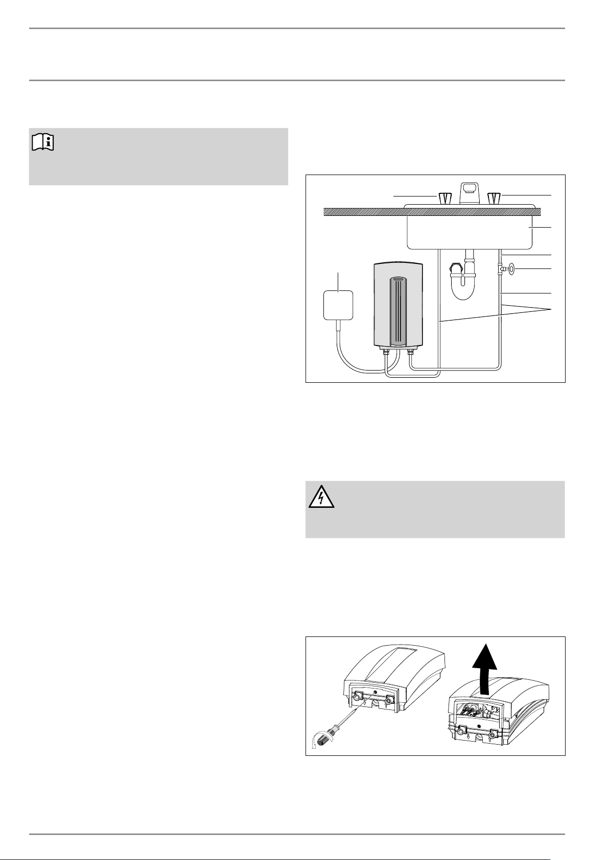
5. Mounting the unit
26_02_02_0330
7
6
1
4
3
2
8
5
1 Electrical junction box
2 Water supply line for faucet installation
3 3/8˝ compression-T
4 Shut-off valve
5 1/2˝ main pipe
6 Sink
7 Cold valve (right)
8 Hot valve (left)
DANGER: Electrocution
The unit must be installed in a vertical position with
the water fittings pointing downward. Do not install
unit where it would routinely be splashed with water.
Electric shock may result.
1. Install DHC as close as possible to the hot water draw-off
point, for example, directly underneath the sink or next to
the shower stall.
2. Install DHC in a frost free area. If frost may occur, remove
unit before freezing temperatures set in.
3. Leave a minimum of 5˝ of clearance on all sides for
servicing.
4. Remove plastic cover.
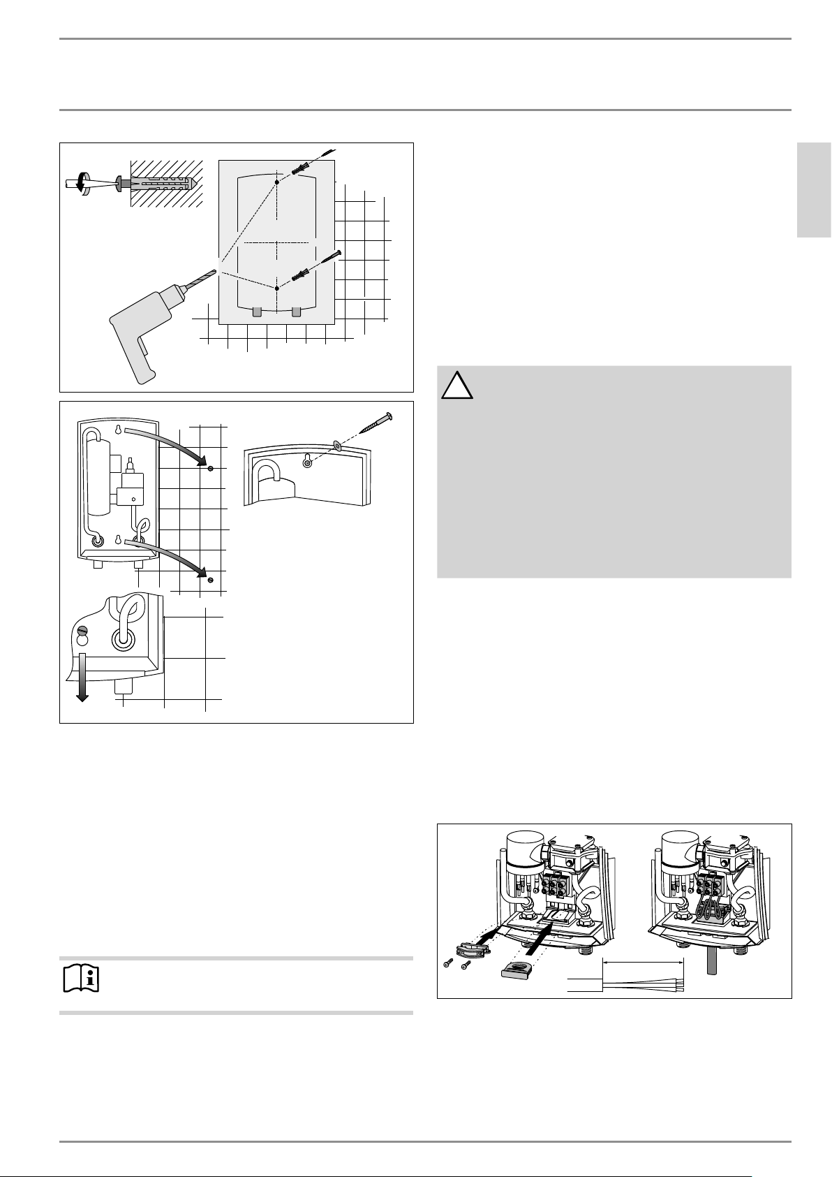
26_02_02_1360
5. Mount unit securely to wall by putting two screws through
mounting holes. Screws and plastic wall anchors for mount-
ing on masonry or wood are provided.
ENGLISH
WWW.STIEBEL-ELTRON-USA.COM DHC | 5
INSTALLATION
WATER CONNECTIONS
26_02_02_033126_02_02_1355
6. Water connections
1. All plumbing work must comply with national and applicable
state and local plumbing codes.
2. A pressure reducing valve must be installed if the cold water
supply pressure exceeds 150 psi (10 bar).
3. Make certain that the cold water supply line has been flushed
to remove any scale and dirt.
4. Install isolating valve in cold water line as shown in illus-
tration. This allows the unit to be isolated for maintenance
purposes.
5. Cold water connection (inlet) is on the right side of the unit,
hot water connection (outlet) is on the left side of unit.
Note
Excessive heat from soldering on copper pipes near the
DHC may cause damage.
6. Tankless water heaters such as the DHC are not required to
be equipped with a Temperature and Pressure Relief Valve
(T&P). If the local inspector will not pass the installation
without a T&P, it should be installed on the hot water outlet
side of appliance.
7. The DHC’s hot water outlet is designed for connection to cop-
per tubing, PEX tubing or a braided stainless steel hose with
a ½˝ NPT female tapered thread.
8. The plumbing on the cold water inlet side needs to be such
that it can easily be removed to allow access to the inlet filter
screen. The easiest way to achieve this is to use a stainless
steel braided hose connector. If soldering near the unit is
necessary, please direct the flame away from the housing of
the unit in order to avoid damage.
9. When all plumbing work is completed, check for leaks and
take corrective action before proceeding.
7. Electrical connection
!
WARNING:
Before beginning any work on the electric installation,
be sure that main breaker panel switches are “off”
to avoid any danger of electric shock. All mounting
and plumbing must be completed before proceed-
ing with electrical hook-up. Where required by local,
state or national electrical codes the circuits should be
equipped with a “ground fault interrupter”.
The unit must be properly grounded in accordance
with state and local codes, or in absence of such
codes, in accordance with national electric code or the
Canadian electric code. Failure to electrically ground
the product could result in serious personal injury or
death.
1. All electrical work must comply with national and applicable
state and local electrical codes.
2. The DHC should be connected to a properly grounded dedi-
cated branch circuit of proper voltage rating. In installa tions
with several DHC units, each unit requires an independent
circuit. Please refer to the technical data table for the correct
wire and circuit breaker size.
3. The wire must be fed through the rubber seal located be-
tween the hot and cold water connections. Then feed wires
through strain relief clamp and tighten clamp down on wire.
The “live” wires must be connected to the slots on the termi-
nal block marked N and L (DHC 3-1 only) or L and L (all other
versions). The ground wire must be connected to slot marked
with the ground symbol.
4. Reinstall plastic cover.
4˝ (100 mm)
26_02_02_0469

6 | DHC WWW.STIEBEL-ELTRON-USA.COM
INSTALLATION
COMMISSIONING
7.1 Terminal block
Consult the chart below for the recommended torque amounts on
the terminal block screws.
Screw Size (mm) Min. Torque (N•cm) Min. Torque (lbf•in)
M5 150-200 13.3-17.7
Using the proper torque specifications to secure wire to the wiring
block helps to avoid personal loss or property damage.10
8. Commissioning
!
WARNING:
Open hot water faucet for a few minutes until water
flow is continuous and all air is purged from water
pipes. The unit’s cover must be installed before the
circuit breakers are turned on.
1. Turn on circuit breaker to bring electrical power to the unit.
2. Open hot water faucet to a degree so that water flow is „typi-
cal“ i.e. until the water flow is the same as that encountered
during normal use.
3. Wait twenty seconds until temperature has stabilized. Then
check water temperature. If temperature is too low, the
water flow rate needs to be reduced. In order to do this,
turn off the unit’s circuit breaker, remove the cover and turn
the flow adjustment screw shown in illustration clockwise
1/2 turn (180 degrees). Then reinstall plastic cover, turn
on circuit breaker and check water temperature. This pro-
cedure should be repeated until the desired temperature is
achieved. In case the water temperature is too high, turn the
flow adjustment screw counter clockwise in the same man-
ner until the desired temperature is achieved. The arrows in
illustration refer to the water temperature.
4. In order to obtain temperature control at a single spout mix-
er-type faucet, restrict cold water flow to faucet by partially
closing the cold water shut-off valve under the sink until cold
water and hot water flow rates are approximately the same.
8.1 Appliance handover
Explain the functions of the appliance to the user. Draw special
attention to the safety information. Hand the operating and instal-
lation instructions to the user.
ENGLISH
WWW.STIEBEL-ELTRON-USA.COM DHC | 7
INSTALLATION
TROUBLESHOOTING
9. Troubleshooting
Symptom Possible cause Solution
No hot water but audible click can be heard when
water is turned on.
Circuit breaker off Circuit breaker on.
Safety thermal cut-out tripped Reset thermal cut-out.
Heater may be undersized See section 11.3, “Temperature increase above ambi-
ent water temperature”, pg. 9
No hot water and no audible click can be heard when
water is turned on
Water flow too low to activate flow switch
Clean faucet aerator.
Open shut-off valve completely.
Increase flow by opening flow adjustment screw
(turn counterclockwise).
Clean filter screen at DHC unit. See section 12, “Spare
parts”, pg. 11.
Water not warm enough
Water flow too high
Reduce water flow by closing flow adjustment screw
(turn clockwise). See section 11.3, “Temperature in-
crease above ambient water temperature”, pg. 9
Voltage too low Supply correct voltage to unit.
If you are not able to resolve a problem please contact us toll
free at 800-582-8423 before removing the unit from the wall.
STIEBEL ELTRON is happy to provide technical assistance. In
most instances, we can resolve the problem over the phone.
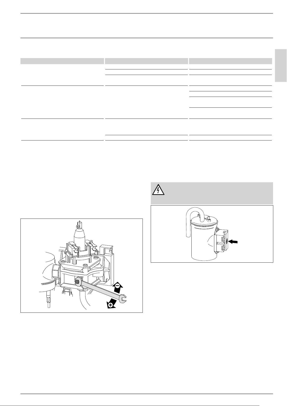
Flow adjustment screw
To lower the water temperature or increase water flow, open the
flow adjustment screw by turning counterclockwise
(-). This de-
creases the water temperature by increasing water volume.
To raise the water temperature or reduce water flow, close the
flow adjustment screw by turning clockwise
(+). This increases
the water temperature by decreasing water volume.
26_02_02_1358
Reset button from safety thermal cut out
DANGER: Electrocution
Do not attempt to reset the safety thermal cutout of
this water heater unless power to the unit has been
completely shut off at the circuit breakers.
26_02_02_1357
8 | DHC WWW.STIEBEL-ELTRON-USA.COM
INSTALLATION
NORMAL MAINTENANCE
10. Normal maintenance
STIEBEL ELTRON DHC tankless heaters are designed for a very long
service life. Actual life expectancy will vary with water quality and
use. The unit itself does not require any regular maintenance.
However, to ensure consistent water flow, it is recommended
to periodically remove scale and dirt that may build up at the
aerator of the faucet or in the shower head. Also, the DHC has
a built in filter screen that should be cleaned from time to time.
In order to do this, turn off the cold water supply at the isolating
valve and remove the ground wire. Twist cold water supply tube
counterclock wise by 90° and pull towards bottom of unit. Clean
screen and put the screen, the cold water supply tube and the
ground wire back into their original position. Please be sure that
the ground wire is reinstalled and that ground screw is securely
tightened after this procedure.
Note:
Other than the filter screen, the DHC does not contain any
parts serviceable by the lay person. In case of malfunction
please contact a licensed plumber or electrician.
11. Technical Data
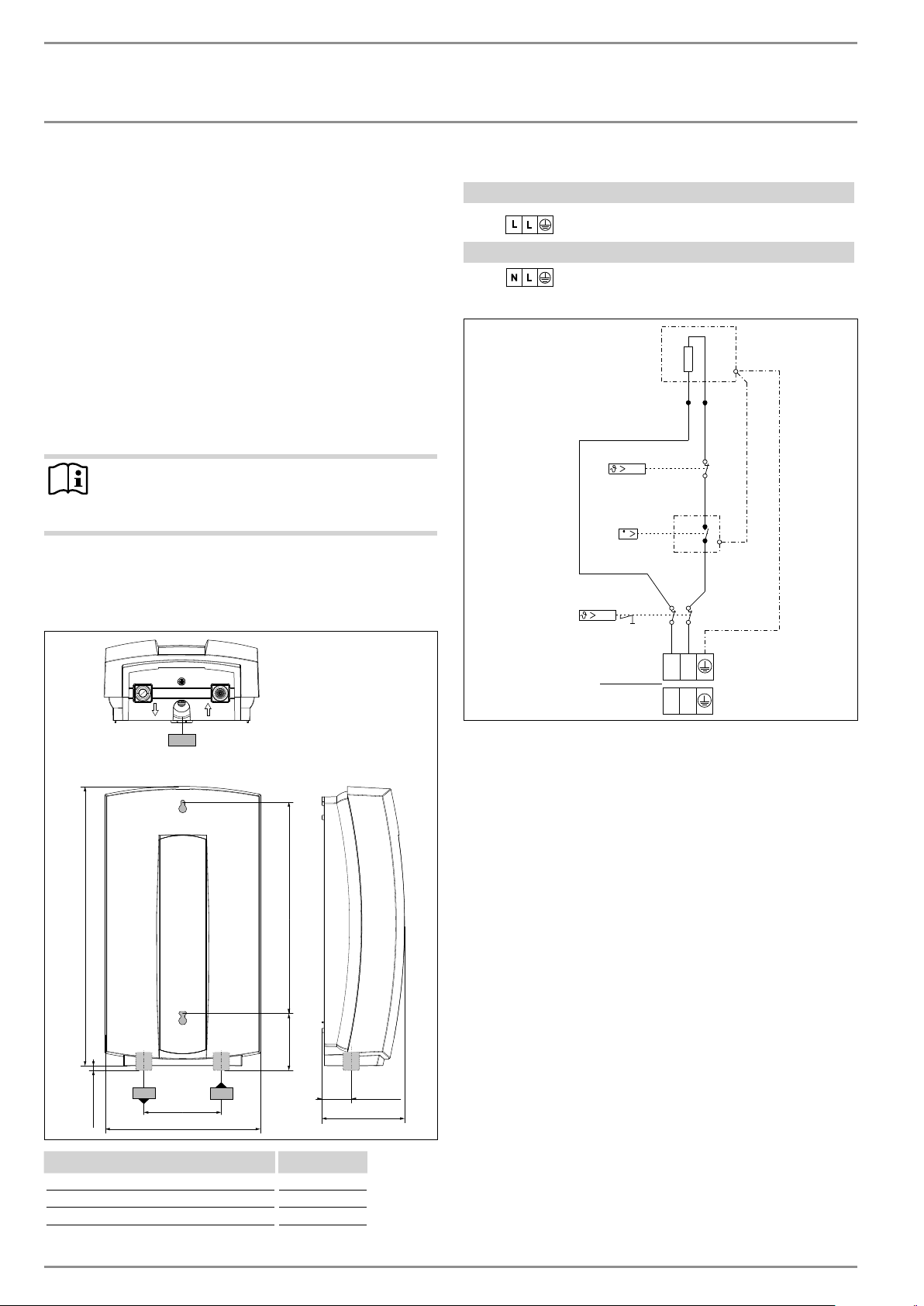
11.1 Dimensions
b01
c06 c01
c01
c06
38 (1.5")
360 (14.17")
200 (7.88")
100 (3.94")
110 (4.33")
273 (10.75")75 (2.953")
8 (0.315")
D0000021558
b01 electrical supply cable
c01 cold water connection 1/2" NPT
c06 hot water connection 1/2" NPT
11.2 Wiring diagram
DHC 3-2, DHC 4-2, DHC 5-2
A 2/GND ~ 208 / 240 V
DHC 4-3
B 1/N/GND ~ 277 V
LL
A
V
NL
B
85_02_02_0008
ENGLISH
WWW.STIEBEL-ELTRON-USA.COM DHC | 9
INSTALLATION
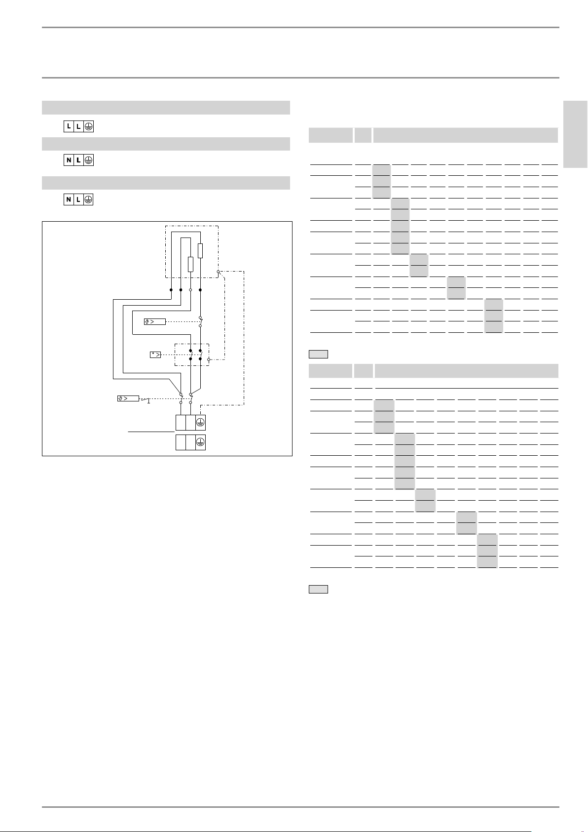
TECHNICAL DATA
DHC 6-2, DHC 8-2, DHC 10-2
A
2/GND ~ 208 / 240 V
DHC 9-3
B 1/N/GND ~ 277 V
DHC 3-1
B 1/N/GND ~ 120 V
V
LL
NL
85_02_02_0009
A
B
11.3 Temperature increase above ambient water
temperature
[ °F ]
Typ kW GPM (gallon per minute)
0.32 0.42 0.48 0.5 0.69 0.75 0.79 1.0 1.5 2.0
DHC 3-1 3.0 65 49 43 41 30 27 26 20 14 10
DHC 3-2
2.5 54 40 35 34 25 23 21 17 11 9
3.3 71 53 47 45 33 30 28 22 15 11
DHC 4-2
2.9 – 47 41 40 29 26 25 20 13 10
3.8 – 61 54 52 38 35 33 26 17 13
DHC 4-3 4.5 – 73 64 61 45 41 39 31 20 15
DHC 5-2
3.6 – 58 51 49 36 33 31 25 16 12
4.8 – 77 68 65 48 44 41 33 22 16
DHC 6-2
4.5 – – 64 61 45 41 39 31 20 15
6.0 – – 85 82 60 55 52 41 27 20
DHC 8-2
5.4 – – – – 54 49 46 37 25 18
7.2 – – – – 71 65 62 49 33 25
DHC 9-3 9.0 - - - - - - 77 58 41 31
DHC 10-2
7.2 – – - – – – 62 49 33 25
9.6 – – - – – – 82 65 44 33
Min. water flow to activate unit
[ °C ]
Typ / Type kW l/min
1.2 1.6 1.8 2.0 2.6 3.0 4.0 5.0 7.5
DHC 3-1
3.0 36 27 24 22 17 14 11 9 6
DHC 3-2
2.5 30 22 20 18 14 12 9 7 5
3.3 39 30 26 24 18 16 12 9 6
DHC 4-2
2.9 – 26 23 21 16 14 10 8 6
3.8 – 34 30 27 21 18 14 11 7
DHC 4-3
4.5 – 40 36 32 25 22 16 13 9
DHC 5-2
3.6 – 32 29 26 20 17 13 10 7
4.8 – 43 38 34 26 23 17 14 9
DHC 6-2
4.5 – – 36 32 25 22 16 13 9
6.0 – – 48 43 33 29 22 17 11
DHC 8-2
5.4 – – – – 30 26 19 15 10
7.2 – – – – 40 34 26 21 14
DHC 9-3 9.0 - - - - - 43 32 26 17
DHC 10-2
7.2 – – – – – 34 26 21 14
9.6 – – – – – 46 34 28 18
Min. water flow to activate unit

10 | DHC WWW.STIEBEL-ELTRON-USA.COM
INSTALLATION
TECHNICAL DATA
11.4 Data table
DHC 3-1 DHC 3-2 DHC 4-2 DHC 4-3 DHC 5-2 DHC 6-2 DHC 8-2 DHC 9-3 DHC 10-2
074050 074052 074053 074051 074054 074424 074055 232204 074056
Electrical details
Voltage 120 V 208 V 240 V 208 V 240 V 277 V 208 V 240 V 208 V 240 V 208 V 240 V 277 V 208 V 240 V
Wattage 3.0 kW 2.5 kW
3.3
kW 2.9 kW 3.8 kW 4.5 kW 3.6 kW 4.8 kW 4.5 kW 6.0 kW 5.4 kW 7.2 kW 9 kW 7.2 kW 9.6 kW
Amperage 25 A 12 A 14 A 14 A 16 A 17 A 18 A 20 A 22 A 25 A 26 A 30 A 32.5 A 35 A 40 A
Min. recommended circuit
breaker size
1
25 A 15 A 15 A 15 A 20 A 20 A 20 A 20 A 25 A 25 A 30 A 30 A 35 A 35 A 40 A
Min. recommended wire size
(copper)
2
10 AWG 14 AWG 14 AWG 12 AWG 12 AWG 12 AWG 10 AWG 10 AWG 8 AWG 8 AWG
Power connection 1/N/GND 2/GND 2/GND 1/N/GND 2/GND 2/GND 2/GND 2/GND 2/GND
Connections
Water connection
3
1/2˝ NPT
Total alkaline earths 2.5 mol/m³
Total hardness (H
2
O) 14 Degree d
Hardness range 2 (average hardness)
Hydraulic data
Rated capacity 0.5 l
Rated capacity 0.13 gal
Values
Max. permissible inlet temp. 86 °F / 30°C
Min. water flow to activate unit 1.2 l/min 1.2 l/min 1.6 l/min 1.6 l/min 1.6 l/min 1.8 l/min 2.6 l/min 3.0 l/min 3.0 l/min
Min. water flow to activate unit 0.32 GPM 0.32 GPM 0.43 GPM 0.43 GPM 0.43 GPM 0.48 GPM 0.69 GPM 0.8 GPM 0.8 GPM
Pressure drop at flow rate 0.023 MPa 0.023 MPa 0.023 MPa 0.023 MPa 0.023 MPa 0.023 MPa 0.025 MPa 0.03 MPa 0.03 MPa
Pressure drop at flow rate 2.88 PSI 2.88 PSI 2.88 PSI 2.88 PSI 2.88 PSI 2.88 PSI 3.13 PSI 3.75 PSI 3.75 PSI
Flow rate for pressure drop 1.2 l/min 1.2 l/min 1.6 l/min 1.6 l/min 1.6 l/min 1.8 l/min 2.6 l/min 3.0 l/min 3.0 l/min
Flow rate for pressure drop 0.32 GPM 0.32 GPM 0.43 GPM 0.43 GPM 0.43 GPM 0.48 GPM 0.69 GPM 0.8 GPM 0.8 GPM
DHW delivery 1.2 l/min 1.2 l/min 1.6 l/min 1.6 l/min 1.6 l/min 1.8 l/min 2.6 l/min 3.0 l/min 3.0 l/min
DHW delivery 0.32 GPM 0.32 GPM 0.43 GPM 0.43 GPM 0.43 GPM 0.48 GPM 0.69 GPM 0.8 GPM 0.8 GPM
Application limits
Max. permissible pressure 1 MPa
Max. permissible pressure 150 PSI
Test pressure 2 MPa
Test pressure 300 PSI
Versions
IP-Rating IP25
Material of the pressure vessel Copper
Heating system Tubular heater
Cover and back panel Plastic
Color white
Dimensions
Height 14.17 in / 360 mm
Width 7.88 in / 200 mm
Depth 4.33 in / 100 mm
Weights
Weight 2.1 kg
Weight 4.6 lb
DHC 3-1, 3-2, 4-2 ship with a 0.5 gpm (1.9 l/min) pressure compensating flow-reducer/aerator that must be installed.
1
This is our recommendation for overcurrent protection sized at 100% of load (DP for 240/208/277 V & SP for 120 V models).
Check local codes for compliance if necessary. Tankless water heaters are considered a non-continuous load.
2
Copper must be used. Conductors should be sized to maintain a voltage drop of less than 3% under load.
3
Suitable for supply with cold water only.
ENGLISH
WWW.STIEBEL-ELTRON-USA.COM DHC | 11
INSTALLATION
SPARE PARTS
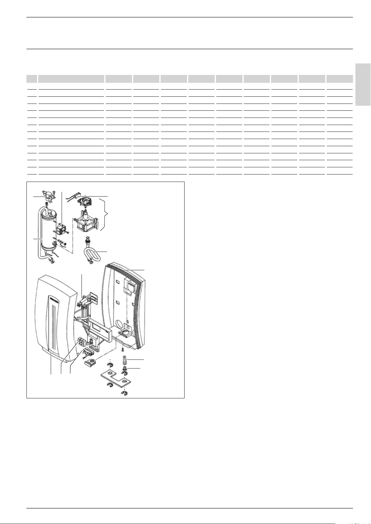
12. Spare parts
No. Spare part DHC 3-1 DHC 3-2 DHC 4-2 DHC 4-3 DHC 5-2 DHC 6-2 DHC 8-2 DHC 9-3 DHC 10-2
1 Heating system 165889 167769 167770 165890 167771 171117 167772 296874 167773
2 Flow switch 165273 165273 162162 162162 162162 171105 162164 162465 162165
3 Thermostat 162472 162472 162472 162472 162472 162472 162472 162472 162472
4 Switch 168026 168026 168026 168026 168026 168026 168026 168026 168026
5 Housing (back) 165891 165891 165891 165891 165891 165891 165891 165891 165891
6 Plumbing connection 170789 170789 170789 170789 170789 170789 170789 170789 170789
7 Housing (front) 165892 165892 165892 165892 165892 165892 165892 165892 165892
8 Safety thermal cut out 162474 162474 162474 162474 162474 162474 162474 162474 162474
9 Wiring block 026010 026010 026010 026010 026010 026010 026010 026010 026010
10 Copper tube 162314 162314 162314 162314 162314 162314 162314 162314 162314
11 Module chassis 162462 162462 162462 162462 162462 162462 162462 162462 162462
12 Wire strain relief clamp 055754 055754 055754 055754 055754 055754 055754 055754 055754
13 Filter screen 275981 275981 275981 275981 275981 275981 275981 275981 275981
D0000043978
4
7
1
3
2
10
5
6
13
912
8
11