Installation, Operation
and Maintenance
MANUAL
CHÂTEAU SERIES
RANGES & COOKTOPS
« Centenaire »
Grand Palais 180
Château 165
Château 150
Château 120
Château 90
Château 75
ANSI/CGA Standard
Designation
85KJ


Page 1
LA CORNUE
IMPORTANT SAFETY INSTRUCTIONS
Read al l instructions before using this appliance. Save these instructions for future reference.
Installation Guide Château Series Centenaire
08NOTINSTAL100/USA-8
July 2014 Anna Kowalczyk
USA & CANADA
— Do not store or use gasoline or other flammable vapors or liquids
in the vicinity of this or any other appliance.
— WHAT TO DO IF YOU SMELL GAS
• Do not try to light any appliance.
• Do not touch any electrical switch.
• Do not use any phone in your building.
• Immediately call your gas supplier from a neighbor's phone.
Fol low the gas supplier's instructions.
• If you cannot reach your gas supplier, call the fire depart-
ment.
— Instal lation and service must be performed by a qualified instal ler,
service agency or the gas supplier.
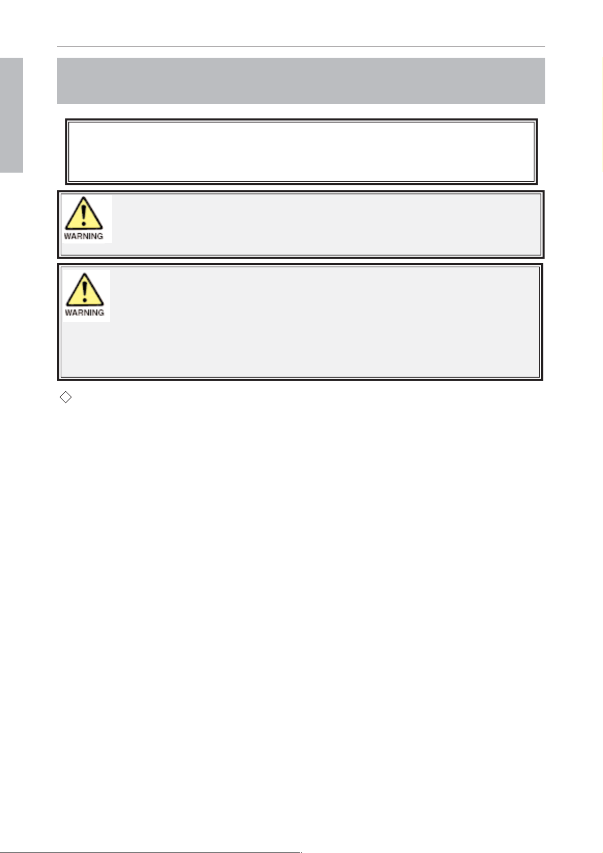
WARNING: IF THE INFORMATION ON THIS MANUAL
IS NOT FOLLOWED EXACTLY
, A FIRE, ELECTRIC SHOCK OR
EXPLOSION MAY RESULT CAUSING PROPERTY DAMAGE, PER-
SONAL INJURY OR DEATH.
CAUTION
DO NOT STORE ITEMS OF INTEREST TO CHILDREN IN CABINETS ABOVE A RANGE OR
ON THE BACKGUARD OF A RANGE
- CHILDREN CLIMBING ON THE RANGE TO REACH
ITEMS COULD BE SERIOUSLY INJURED.
WARNING
(Only for the models
Château 90 & Château 75)
THE ANTI-TIP DEVICE SUPPLIED
WITH THE RANGES CHATEAU 90 &
CHATEAU 75 MUST BE CORRECTLY
FITTED WHEN THE APPLIANCE IS
INSTALLED. THIS WILL REDUCE RISK
OF TIPPING OF THE APPLIANCE
FROM ABNORMAL USAGE OR BY
EXCESSIVE LOADING OF THE OVEN
DOOR.
Read al l instructions before using this appliance. Save these instructions for future reference.
Page 2
LA CORNUE
Installation Guide Centenaire
08NOTINSTAL100/USA-8
IMPORTANT SAFETY INSTRUCTIONS
USA & CANADA
u
Proper Instal lation - Be sure your appliance is properly instal led and
grounded by a qualified technician.
The instal lation of your La Cornue appliance must conform with local codes
or, in the absence of local codes, in the USA with the ”National Fuel Gas
Code”, ANSI Z223.1NFPA 54, latest edition, and, in Canada, with CAN/CGA
- B149.1, and CAN CGA - B149.2, ”Instal lation Code for Gas Burning
Appliances”.
The appliance must be electrical ly instal led and grounded in accordance with
local codes or in the absence of such codes with the latest edition of the
”National Electrical Code”, ANSI/NFPA 70 in the USA, and CSA C22.2
”Canadian Electrical Code” - in Canada.
Important - Save the instal lation instructions for the local electrical
inspector’s use.
In The Commonwealth Of Massachusetts
This product must be instal led in compliance with CMR 248, the
Massachusetts Fuel Gas and Plumbing Code, by a licensed plumber or gas
fitter when instal led within the Commonwealth of Massachusetts.
A ”T” hand le type manual gas valve must be instal led in the gas supply line
to this appliance.
WARNING: NEVER cover any slots, holes or passages in the
oven bottom or cover an entire rack with materials such as alumi-
num foil. Doing so blocks airflow through the oven and may cause
carbon monoxide poisoning. Do not use aluminum foil to line surface unit
drip bowls or oven bottoms, except as suggested in the manual. Improper
instal lation of these liners may result in a risk of electric shock, or fire.
WARNING: NEVER use this appliance as a space heater to heat
or warm the room. Doing so may result in carbon monoxide poiso-
ning and overheating of the oven
This book contains many important safety messages.
Always read and obey all safety messages.
Instal ler: Leave these instructions with the appliance

Read al l instructions before using this appliance. Save these instructions for future reference.
Page 3
LA CORNUE
Installation Guide Centenaire
08NOTINSTAL100/USA-8
IMPORTANT SAFETY INSTRUCTIONS
This appliance is not intended for use by persons (including children) with redu-
ced physical, sensory or mental capabilities, or lack of experience and knowled-
ge, unless they have been given supervision or instruction concerning use of the
appliance by a person responsible for their safety.
Al l our cooking appliances are intended for domestic use only; i.e., not profes-
sional. In the event of non-domestic use, the manufacturer shall not incur any
liability, and the warranty shal l be considered void.
USA & CANADA
In Case of Fire
Do not use water on grease fires. Never pick up a flaming pan.
Turn the controls off. Smother a flaming pan on a cooktop bur-
ner by covering the pan completely with a wel l fitting lid or baking
tray. If available use a multipurpose dry chemical or foam-type fire
extinguisher.
If fire is in an oven pan, smother by closing oven door. Open doors and
windows or if a hood is fitted turn it on to remove smoke and odor.
To Prevent Fire or Smoke Damage
Before using the range make sure all the packing materials have been
removed. Always keep the area around the range free from combus-
tible materials, gasoline, and other flammable vapors and liquids.
If the range is instal led near a window, proper precautions should be
taken to prevent curtains from blowing over the burners.
NEVER leave any items on the range cooktop. The hot air from an
oven vent may ignite flammable items and may increase pressure in
closed containers, which may cause them to burst. Many aerosol-type
spray cans are EXPLOSIVE when exposed to heat and may be highly
flammable. Avoid their use or storage near an appliance.
Many plastics wil l burn and most are damaged by heat. Keep plastic
items away from parts of the range that may become warm or hot. Do
not leave plastic items on the cooktop as they may burn, melt or soften
if left too close to a vent or a lighted burner.

Read al l instructions before using this appliance. Save these instructions for future reference.
Page 4
LA CORNUE
Installation Guide Centenaire
08NOTINSTAL100/USA-8
IMPORTANT SAFETY INSTRUCTIONS
USA & CANADA
u Purchaser of this appliance must post in a prominent location instructions to
be fol lowed in the event the user smells gas. This information shal l be obtai-
ned by consulting your local gas supply company.
u Keep appliance area free and clear from combustibles.
u It is essential that the kitchen where your appliance wil l be instal led has
excel lent ventilation to the outside for steam and combustion gases removal.
u VENTILATING HOODS:
- Clean Ventilating Hoods Frequently - Grease should not be allowed to
accumulate on hood or filter.
- When flaming foods under the hood, turn the fan on.
u Do not use air recycling systems.
u ”La Cornue” can provide customers with hoods in materials matching the
appliance. The hoods are sold without blower systems since every instal lation
is unique. The individual requirements are best handled by a professional
ventilation specialist.
u Adequate clearance must be provided for air openings into the combustion
chamber.
u Minimum clearances to combustible construction see item 1.2. page 35.
u Adequate clearance must be provided for proper operation and servicing of
the appliance.
u A manual valve must be instal led in an accessible location in the gas piping
external to the appliance for the purpose of turning on or shutting off gas to
the appliance.
u The range and its individual shutoff valve must be disconnected from the gas
supply piping system during any pressure testing of that system at test
pressures in excess of 1/2 psig (3.5 kPa).
u The appliance must be isolated from the gas supply piping system by closing
its individual manual shutoff valve during any pressure testing of the gas
supply piping system at test pressures equal to or less than 1/2 psig (3.5 kPa).

Read al l instructions before using this appliance. Save these instructions for future reference.
Page 5
LA CORNUE
Installation Guide Centenaire
08NOTINSTAL100/USA-8
IMPORTANT SAFETY INSTRUCTIONS
USA & CANADA
u Leak testing of the appliance shal l be conducted according to the
manufacturer’s instructions.
u The inlet gas supply pressure to the appliance must be within the fol lowing limits:
u Keep this manual for future reference.
u Do Not Leave Children Alone - Children should not be left alone or unat-
tended in area where appliance is in use. They should never be al lowed to
sit or stand on any part of the appliance.
Do not allow children to climb or play around the range. The weight of a
child on an open door may cause the range to tip, resulting in serious
burns or other injury.
Teach them not to play with controls or any other part of the range.
Destroy the carton and plastic bags after unpacking the range. Never allow
children to play with packaging material.
u Wear Proper Apparel - Loose-fitting or hanging garments should never be
worn while using the appliance.
u User Servicing - Do not repair or replace any part of the appliance unless
specifical ly recommended in the manual. Al l other servicing should be
referred to a qualified technician.
u Use Proper Pan Size - This appliance is equipped with more surface units
of different size. Select utensils having flat bottoms large enough to cover
the surface unit heating element. The use of undersized utensils wil l expo-
se a portion of the heating element to direct contact and may result in igni-
tion of clothing. Proper relationship of utensil to burner wil l also improve
efficiency.
u The top burner flame size should be adjusted so it does not extendbeyond the
edge of the cooking utensil. This instruction is based on safety considerations.

Read al l instructions before using this appliance. Save these instructions for future reference.
Page 6
LA CORNUE
Installation Guide Centenaire
08NOTINSTAL100/USA-8
IMPORTANT SAFETY INSTRUCTIONS
USA & CANADA
u Use Only Dry Potholders or Oven Gloves - Moist or damp potholders on
hot surfaces may result in burns from steam. Never let a potholder touch
hot heating elements.
Do not use a towel or other bul ky cloth in place of a glove. They might
catch fire if they touch a hot surface.
Use dry oven gloves when applicable - using damp gloves might result in steam
burns when you touch a hot surface. Never operate the range with wet hands.
u Never Leave Surface Units Unattended at High Heat Settings - Boilover
causes smoking and greasy spil lovers that may ignite.
u Make Sure Reflector Pans or Drip Bowls Are in Place - Absence of these
pans or bowls during cooking may subject wiring or components undernea-
th to damage.
u Glazed Cooking Utensils - Only certain types of glass, glass/ceramic, cera-
mic, earthenware, or other glazed utensils are suitable for range-top servi-
ce without breaking due to the sudden change in temperature.
u Utensil Hand les Should Be Turned Inward and Not Extend Over Adjacent
Surface Units - To reduce the risk of burns, ignition of flammable mate-
rials, and spil lage due to unintentional contact with the utensil, the hand le
of a utensil should be positioned so that it is turned inward, and does not
extend over adjacent surface units.
u DEEP FAT FRYERS: Use extreme caution when moving the grease kettle
or disposing of hot grease.
u Do Not Soak Removable Heating Elements - Heating elements should
never be immersed in water.
u Use Care When Opening Oven Door - Let hot air or steam escape before
removing or replacing food.
u Do Not Heat Unopened food Containers - Build-up of pressure may cause
container to burst and result in injury.
u Do not use the oven for storage - This instruction is based on safety consi-
derations. Flammable materials should not be stored in an oven, the range
storage drawer or near the cooktop burners. This includes paper, plastic
and cloth items, such as cookbooks, plasticware and towels, as well as flam-

Read al l instructions before using this appliance. Save these instructions for future reference.
Page 7
LA CORNUE
Installation Guide Centenaire
08NOTINSTAL100/USA-8
IMPORTANT SAFETY INSTRUCTIONS
USA & CANADA
mable liquids. Do not store explosives, such as aerosol cans, on or near the
appliance.
Flammable materials may explode and result in fire or property damage.
u Keep oven vent ducts unobstructed.
u Placement of Oven Racks - Always place oven racks in desired location
while oven is cool. If rack must be moved while oven is hot, do not let
potholder contact hot heating element in oven.
u To avoid personal injury, do not sit, stand or lean on oven doors or drawer.
Leaning, sitting or stepping on the doors or drawer of this range can result
in serious injuries and also cause damage to the range. Do not al low anyone
to climb, stand or hang on any part of the range.
u The bottom drawer is for storing oven trays and other cooking utensils. It
can get very warm, don’t store anything in it, which may melt or catch fire.
Never store flammable materials in the drawer. This includes paper, plastic
and cloth items, such as cookbooks, plastic ware and towels, as well as
flammable liquids. Do not store explosives, such as aerosol cans, on or near
the appliance.
Flammable materials may explode and result in fire or property damage.
u Wear Suitable Clothing - Never wear loose-fitting or hanging clothes while
using the range. Be careful when reaching for items stored in cabinets over
the cooktop. Flammable material could be ignited if brought in contact
with a burner flame or hot surface and may cause severe burns.
u Important Safety Notice and Warning - The California Safe Drinking
Water and Toxic Enforcement Act of 1986 (Proposition 65) requires the
Governor of California to publish a list of substances known to the State of
California to cause cancer or reproductive harm, and requires businesses
to warn customers of potential exposures to such substances.
This appliance contains or produces a chemical or chemicals which can
cause death or serious il lness and which are known to the state of
California to cause cancer, birth defects or other reproductive harm.
Users of this appliance are hereby warned that the burning of gas can
result in low-level exposure to some of the listed substances, including ben-
zene, formaldehyde and soot, due primarily to the incomplete combustion
of natural gas or liquid petroleum (LP) fuels. Properly adjusted burners
wil l minimize incomplete combustion.

Read al l instructions before using this appliance. Save these instructions for future reference.
Page 8
LA CORNUE
Installation Guide Centenaire
08NOTINSTAL100/USA-8
IMPORTANT SAFETY INSTRUCTIONS
Exposure to these substances can also be minimized by properly venting
with an open window or using a ventilation fan or hood.
To reduce the risk from substances in the fuel or from fuel combustion
make sure this appliance is instal led, operated, and maintained according
to the instructions in this booklet.
u Quality of Flames - On Natural Gas the burners’ flames should be a blueish
color with, at most, a slight yellowish fringe. On Propane gas the flames
may be ”softer”. The cooktop burner flames may have a slight yel lowish
tip.
If the flame burns with a long white tip you should call for service.
MAKE SURE THE FLOW OF COMBUSTION AND VENTILATION AIR
TO THE RANGE IS UNOBSTRUCTED.
DO NOT TOUCH SURFACE UNITS, AREAS NEAR UNITS, HEATING
ELEMENTS OR INTERIOR SURFACES OF OVEN - Surface units and
heating elements may be hot even though they are dark in color. Areas near
surface units and interior surfaces of an oven may become hot enough to
cause burns.
During and after use, do not touch, or let clothing or other flammable
materials contact surface units, areas near units, heating elements or inter-
ior surfaces of oven until they have had sufficient time to cool. Other surfa-
ce of the appliance may become hot enough to cause burns - among these
surfaces are oven vent openings and surface near these openings, oven
doors, etc.
IMPORTANT: Never keep pet birds in the kitchen or in rooms where the
fumes from the kitchen could reach. Birds have a very sensitive respiratory
system. Fumes released due to overheated cooking oil, fat, margarine and
overheated non-stick cookware may be harmful.
You can find this manual on fol lowing web sites:
www.lacornueusa.com
www.lacornue.com/ca
USA & CANADA

Page 9
LA CORNUE
Installation Guide Centenaire
08NOTINSTAL100/USA-8
USA & CANADA
Le Château 150
Dear Customer,
Thank you for choosing the La Cornue cooking product. We hope that you will derive a lot of enjoyment
from cooking delicious meals with it.
The aim of this document is to make you familiar with the potential provided by a professional quality
product designed for discriminating individuals, and to facilitate its maintenance.
Above all, a La Cornue product is manufactured using noble and pure materials. The choices made for
some components, such as brass for the burners and cast-iron for the gas simmering plate, are the
result of criteria of technicality and professional performance, which are not attainable with other
materials or protective treatments. We are very much attached to the authenticity of our stoves and
we are convinced that you will appreciate them even more as you use them.
In order to make sure that you will be satisfied with your product for a long time, we recommend that
you follow the advice given in this manual.
Thank you for choosing us,
Kind regards,
Xavier Dupuy
President

Contents CONTENTS
Page 10
LA CORNUE
Installation Guide Centenaire
08NOTINSTAL100/USA-8
USA & CANADA
CONTENTS
Page
IMPORTANT SAFETY INSTRUCTIONS ............................................................. 1
D
ESCRIPTION ........................................................................................................... 11
1. Le Grand Palais 180 ..................................................................................... 12
2. Le Château
®
165 .......................................................................................... 15
3. Le Château
®
150 .......................................................................................... 18
4. Le Château
®
120 .......................................................................................... 22
5. Le Château
®
90 ............................................................................................ 26
6. Le Château
®
75 ............................................................................................ 30
I
NSTALLATION .......................................................................................................... 33
B
EFORE DELIVERY .............................................................................................. 33
1. Safety requirements ...................................................................................... 33
2. Electrical supply ............................................................................................ 34
3. Gas supply ..................................................................................................... 34
4. Installation .................................................................................................... 34
H
ANDLING INSTRUCTIONS .................................................................................. 35
A
SSEMBLY INSTRUCTIONS ................................................................................... 37
1. Handrail installation ..................................................................................... 37
2. Riser installation ........................................................................................... 37
3. Height adjustment ......................................................................................... 37
4. Gas chimney protection installation ............................................................. 38
C
ONNECTIONS .................................................................................................... 38
1. Nameplate label ............................................................................................ 39
2. Electrical connection ..................................................................................... 39
3. Gas connection .............................................................................................. 41
O
PERATION .............................................................................................................. 43
1. Tests ............................................................................................................... 43
2. Starting with the ovens ................................................................................. 44
3. Starting with the cooktop elements .............................................................. 46
M
AINTENANCE ......................................................................................................... 46
I
MPORTANT INFORMATION .................................................................................. 46
1. Adjustment of the low flame settings ........................................................... 47
2. Fuel conversion ............................................................................................. 47
3. Converting for High Altitude ........................................................................ 49
4. Gas Pressure Regulator ................................................................................. 49
5. Replacing the oven light ............................................................................... 50
E
LECTRICAL DIAGRAMS ...................................................................................... 51
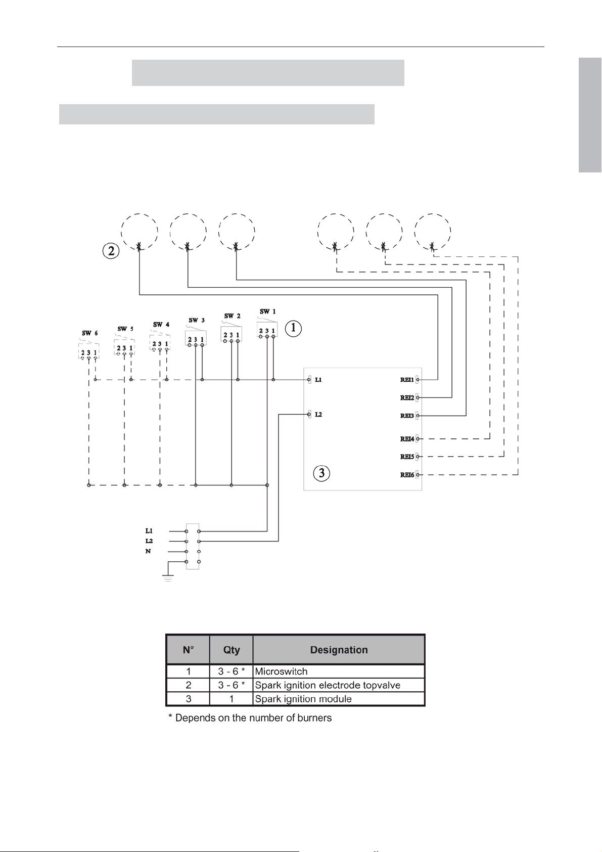
1. Gas cooktop electronic ignition ..................................................................... 51
2. Electric Cooktop section ................................................................................ 52
3. Gas Oven - electronic ignition ...................................................................... 53
4. Electric Oven ................................................................................................. 54
W
ARRANTY .............................................................................................................. 55
A
DDRESS ................................................................................................................. 56
Installation Guide Centenaire
08NOTINSTAL100/USA-8
D
D
E
E
S
S
C
C
R
R
I
I
P
P
T
T
I
I
O
O
N
N
The La Cornue ”Château Centenaire” series consist of 6 models of stoves and hobs:
- Le Grand Palais 180, width 70
7
/8” (1,800 mm).
- Le Château 165, width 65” (1,650 mm).
- Le Château 150, width 59” (1,500 mm).
- Le Château 120, width 47
1
/4” (1,200 mm).
- Le Château 90, width 35” (900 mm).
- Le Château 75, width 29
1
/2
” (750 mm).
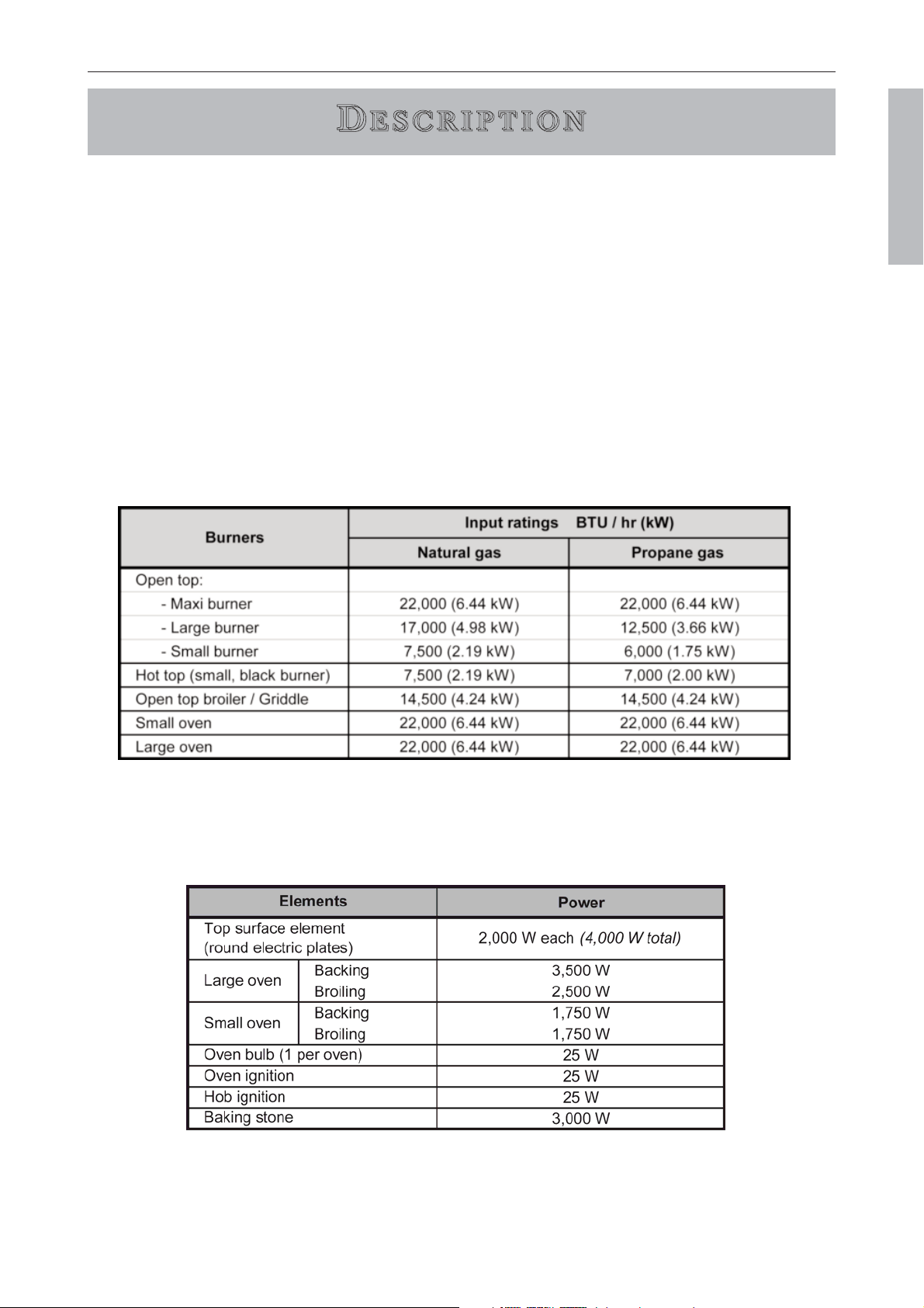
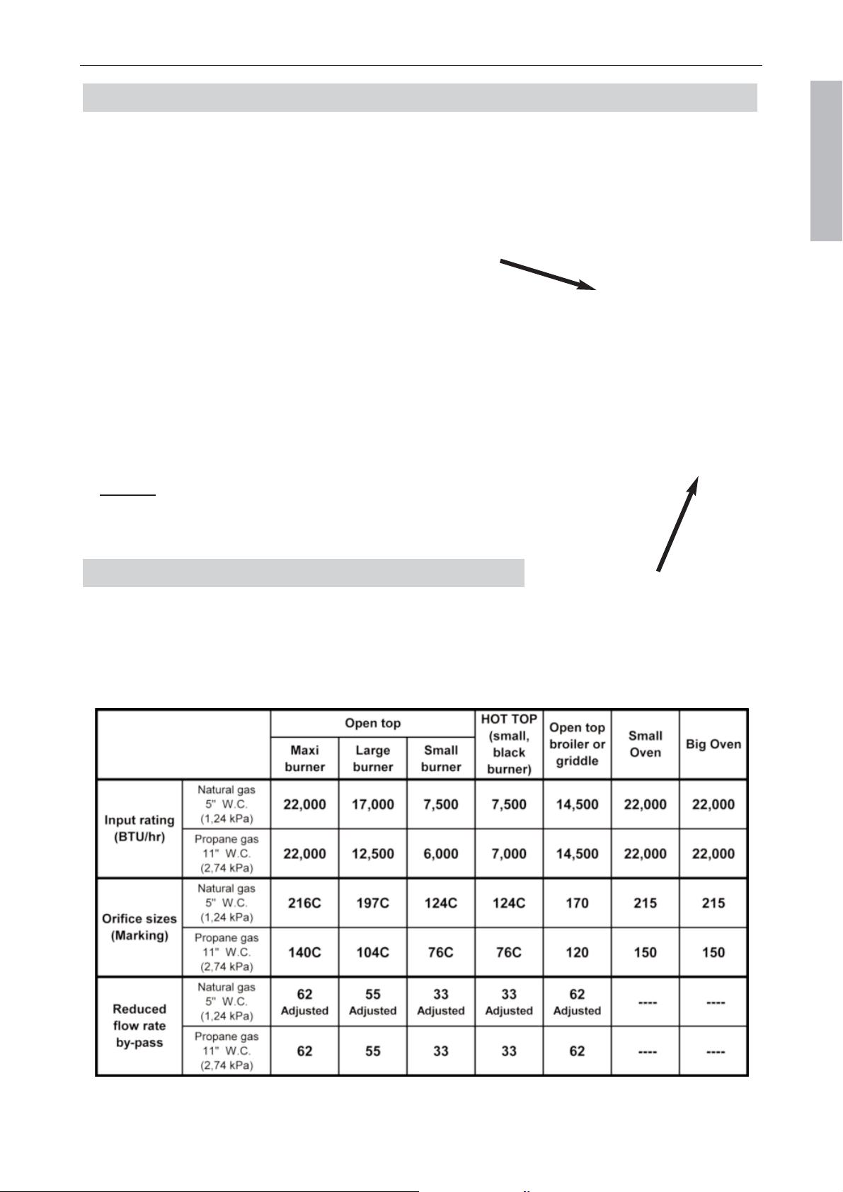
Refer to nameplate to determine type of gas for wich appliance is equiped.
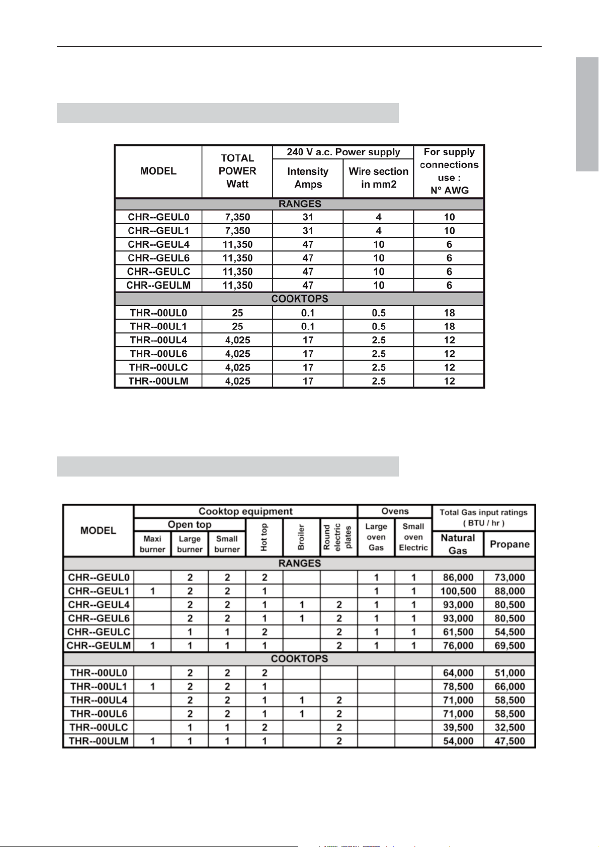
Gas input ratings for each kind of burner (BTU/hr):
Electrical power supplied by each heating element (Watts):
DESCRIPTION Description
Page 11
LA CORNUE
USA & CANADA
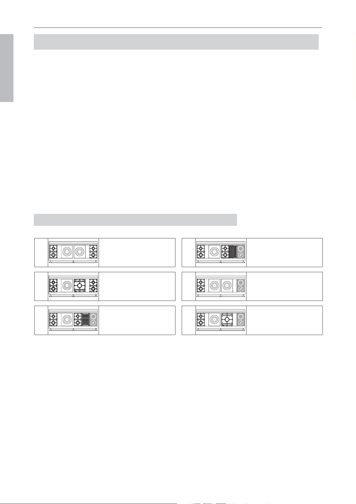
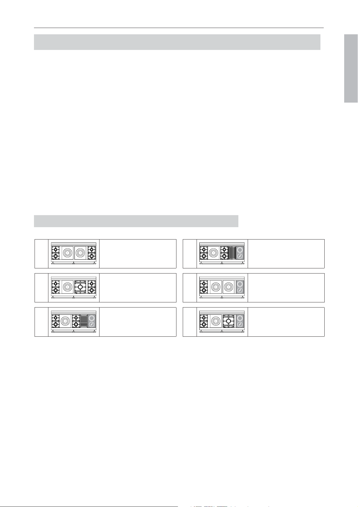
2 gas burners (small burner at the rear)
1 gas hotplate
2 gas burners (small burner at the rear)
1 reversible gas snack griddle
2 round electric plates
2 gas burners (small burner at the rear)
2 gas hotplates
2 round electric plates
N6
2 gas burners (small burner at the rear)
1 gas hotplate
2 gas burners (small burner at the rear)
1 gas lava rock grill
2 round electric plates
N4
N1
2 gas burners (small burner at the rear)
1 gas hotplate
1 maxi burner
2 gas burners (small burner at the rear)
The ”Le Grand Palais 180” range, one of the models of the ”La Cornue” series consists of:
— 2 thermostatically-controlled large vaulted ovens, gas and electric (only ranges).
— One cooktop bounded at the rear by a stainless steel backsplash creating a gap between the
range and the wall, thus ensuring the removal of burnt gases and smells (ranges and cooktops).
Le Grand Palais 180 DESCRIPTION
Page 12
LA CORNUE
Installation Guide Centenaire
08NOTINSTAL100/USA-8
USA & CANADA
1.
1.
D
D
ESCRIPTION
ESCRIPTION
”L
”L
E
E
G
G
RAND
RAND
P
P
ALAIS
ALAIS
180”
180”
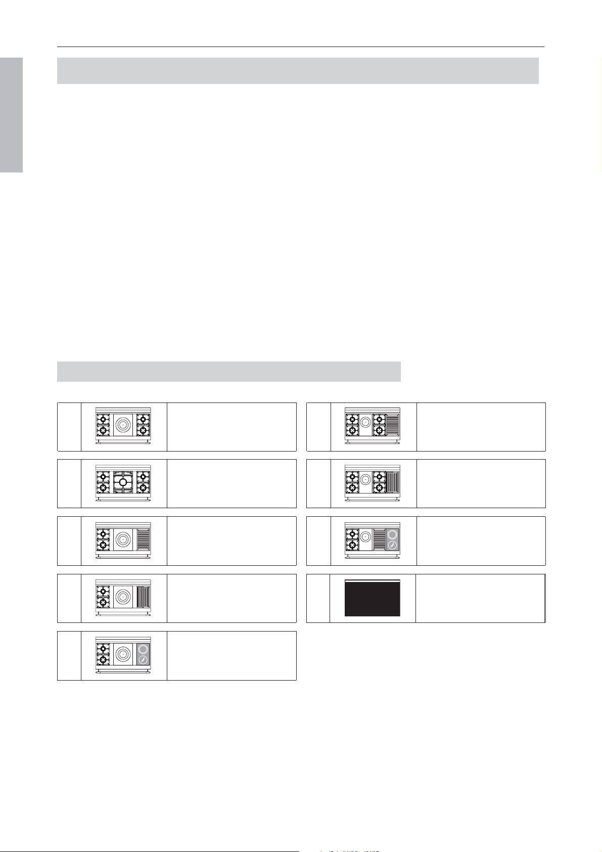
HOB CONFIGURATIONS
2 gas burners (small burner at the rear)
2 gas hotplates
2 gas burners (small burner at the rear)
N0
NC
2 gas burners (small burner at the rear)
1 gas hotplate
1 maxi burner
2 round electric plates
NM

Ranges Cooktops
— Appliance height: 36” (914 mm) 7
7
/8” (200 mm)
— Height with backsplash: 38” (964 mm) 9
7
/8
” (250 mm)
— Width: 70
7
/8” (1,800 mm) 70
7
/8” (1,800 mm)
— Weight: 280 to 320 kg, 100 to 130 kg according to the models
(617 to 705 lbs) (220 to 286 lbs)
— Depth to the wall:
- Front: 26
1
/8” (665 mm)
- Rail: 31” (785 mm)
- Hob edge: 27
1
/2” (700 mm)
Thickness: 1
5
/8” (40 mm)
DESCRIPTION Le Grand Palais 180
Page 13
LA CORNUE
Installation Guide Centenaire
08NOTINSTAL100/USA-8
USA & CANADA
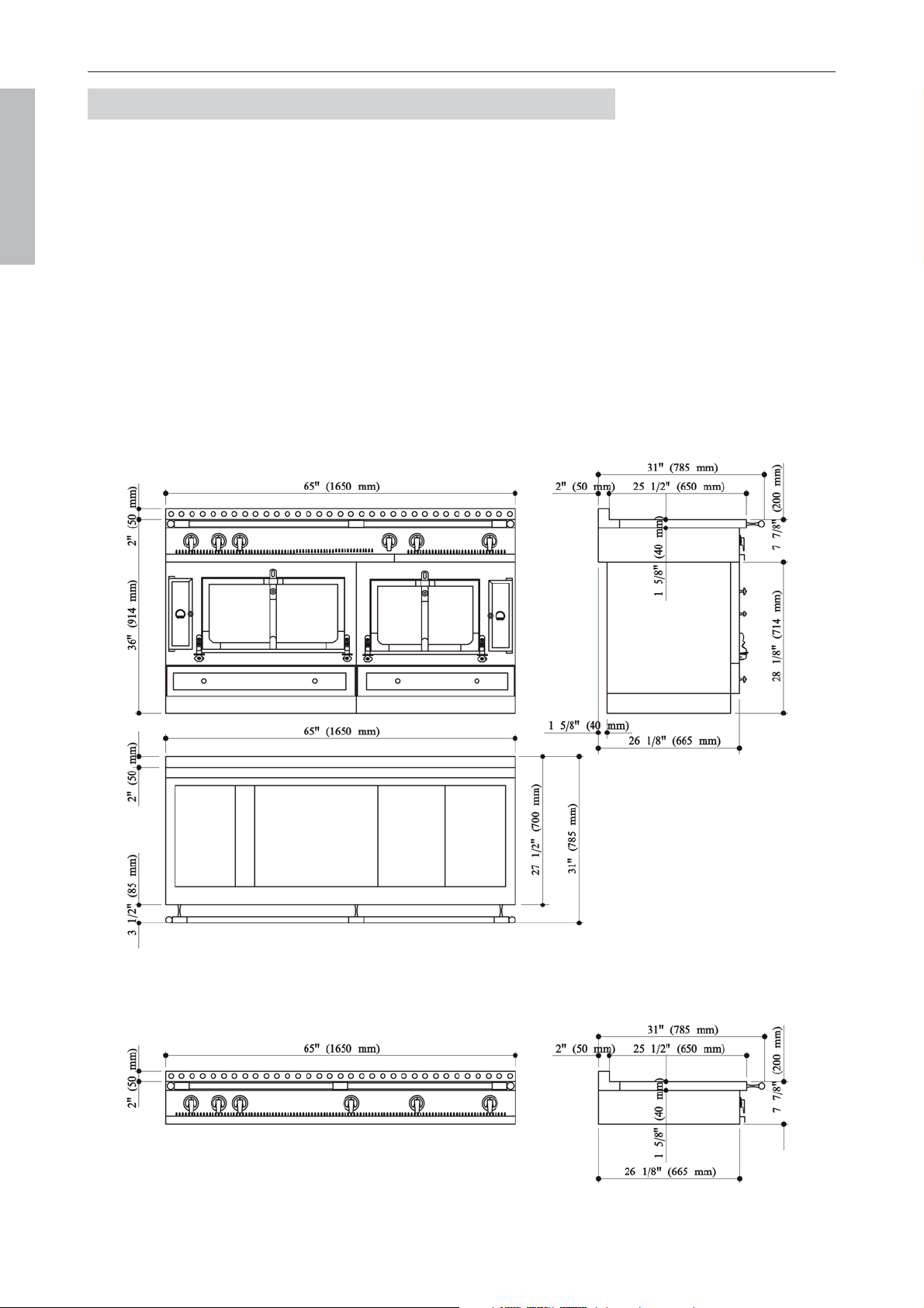
DIMENSIONS
Cooktop - model TGP
Range - model GPA

GAS SUPPLY INFORMATION
For each gas type and for each model, the tables below summarize the total electric power (W) and the
input ratings (BTU/hr).
Le Grand Palais 180 DESCRIPTION
Page 14
LA CORNUE
Installation Guide Centenaire
08NOTINSTAL100/USA-8
USA & CANADA
ELECTRIC SUPPLY INFORMATION
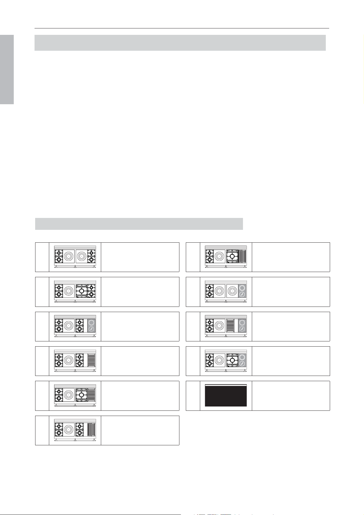
DESCRIPTION Le Château
®
165
2 gas burners (small burner at the rear)
1 gas hotplate
1 maxi burner
2 round electric plates
LM
2 gas burners (small burner at the rear)
2 gas hotplates
2 round electric plates
LC
2 gas burners (small burner at the rear)
1 gas hotplate
2 gas burners (small burner at the rear)
1 reversible gas snack griddle
2 round electric plates
L6
2 gas burners (small burner at the rear)
1 gas hotplate
2 gas burners (small burner at the rear)
1 gas lava rock grill
2 round electric plates
L4
2 gas burners (small burner at the rear)
1 gas hotplate
1 maxi burner
2 gas burners (small burner at the rear)
L1
2 gas burners (small burner at the rear)
2 gas hotplates
2 gas burners (small burner at the rear)
L0
Page 15
LA CORNUE
Installation Guide Centenaire
08NOTINSTAL100/USA-8
USA & CANADA
HOB CONFIGURATIONS
The ”Le Château 165” range, one of the models of the ”La Cornue” series consists of:
— 2 thermostatically-controlled vaulted ovens, 1 large gas oven and 1 small electric oven (only
ranges).
— One cooktop bounded at the rear by a stainless steel backsplash creating a gap between the
range and the wall, thus ensuring the removal of burnt gases and smells (ranges and cooktops).
2.
2.
D
D
ESCRIPTION
ESCRIPTION
”L
”L
E
E
C
C
HÂTEAU
HÂTEAU
®
®
165”
165”
Cooktop - model THR
Range - model CHR
Ranges Cooktops
— Appliance height: 36” (914 mm) 7
7
/8” (200 mm)
— Height with backsplash: 38” (964 mm) 9
7
/8
” (250 mm)
— Width: 65” (1,650 mm) 65” (1,650 mm)
— Weight: 260 to 290 kg, 90 to 130 kg according to the models
(573 to 639 lbs) (198 to 286 lbs)
— Depth to the wall:
- Front: 26
1
/8
” (665 mm)
- Rail: 31” (785 mm)
- Hob edge: 27
1
/2” (700 mm)
Thickness: 1
5
/8” (40 mm)
DIMENSIONS
Le Château
®
165 DESCRIPTION
Page 16
LA CORNUE
Installation Guide Centenaire
08NOTINSTAL100/USA-8
USA & CANADA
DESCRIPTION Le Château
®
165
Page 17
LA CORNUE
Installation Guide Centenaire
08NOTINSTAL100/USA-8
USA & CANADA
For each gas type and for each model, the tables below summarize the total electric power (W) and the gas
input ratings (BTU/hr).
ELECTRIC SUPPLY INFORMATION
GAS SUPPLY INFORMATION
2 gas burners (small burner at the rear)
2 gas hotplates
2 round electric plates
KC
2 gas burners (small burner at the rear)
1 gas hotplate
1 gas lava rock grill
2 round electric plates
KD
2 gas burners (small burner at the rear)
1 gas hotplate
1 maxi burner
2 round electric plates
KM
2 gas burners (small burner at the rear)
1 gas hotplate
1 reversible gas snack griddle
2 round electric plates
KZ
2 gas burners (small burner at the rear)
1 gas hotplate
1 maxi burner
1 reversible gas snack griddle
K9
2 gas burners (small burner at the rear)
1 gas hotplate
2 gas burners (small burner at the rear)
1 gas lava rock grill
K5
2 gas burners (small burner at the rear)
1 gas hotplate
1 maxi burner
1 gas lava rock grill
K6
2 gas burners (small burner at the rear)
1 gas hotplate
2 gas burners (small burner at the rear)
1 reversible gas snack griddle
K8
2 gas burners (small burner at the rear)
1 gas hotplate
2 gas burners (small burner at the rear)
2 round electric plates
K3
2 gas burners (small burner at the rear)
2 gas hotplates
2 gas burners (small burner at the rear)
K0
2 gas burners (small burner at the rear)
1 gas hotplate
1 maxi burner
2 gas burners (small burner at the rear)
K1
The ”Le Château 150” range, one of the models of the ”La Cornue” series consists of:
— 2 thermostatically-controlled small vaulted ovens, gas and electric (only ranges).
— One cooktop bounded at the rear by a stainless steel backsplash creating a gap between the
range and the wall, thus ensuring the removal of burnt gases and smells (ranges and cook-
tops).
Le Château
®
150 DESCRIPTION
Page 18
LA CORNUE
Installation Guide Centenaire
08NOTINSTAL100/USA-8
USA & CANADA
HOB CONFIGURATIONS
3.
3.
D
D
ESCRIPTION
ESCRIPTION
”L
”L
E
E
C
C
HÂTEAU
HÂTEAU
®
®
150”
150”

DESCRIPTION Le Château
®
150
Ranges Cooktops
— Appliance height: 36” (914 mm) 7
7
/8” (200 mm)
— Height with backsplash: 38” (964 mm) 9
7
/8
” (250 mm)
— Width: 59” (1,500 mm) 59” (1,500 mm)
— Weight: 250 to 280 kg, 80 to 100 kg according to the models
(550 to 617 lbs) (176 to 220 lbs)
— Depth to the wall:
- Front: 26
1
/8” (665 mm)
- Rail: 31” (785 mm)
- Hob edge: 27
1
/2” (700 mm)
Thickness: 1
5
/8” (40 mm)
Page 19
LA CORNUE
Installation Guide Centenaire
08NOTINSTAL100/USA-8
USA & CANADA
DIMENSIONS
Cooktop - model TH5
Range - model CH5
Le Château
®
150 DESCRIPTION
Page 20
LA CORNUE
Installation Guide Centenaire
08NOTINSTAL100/USA-8
USA & CANADA
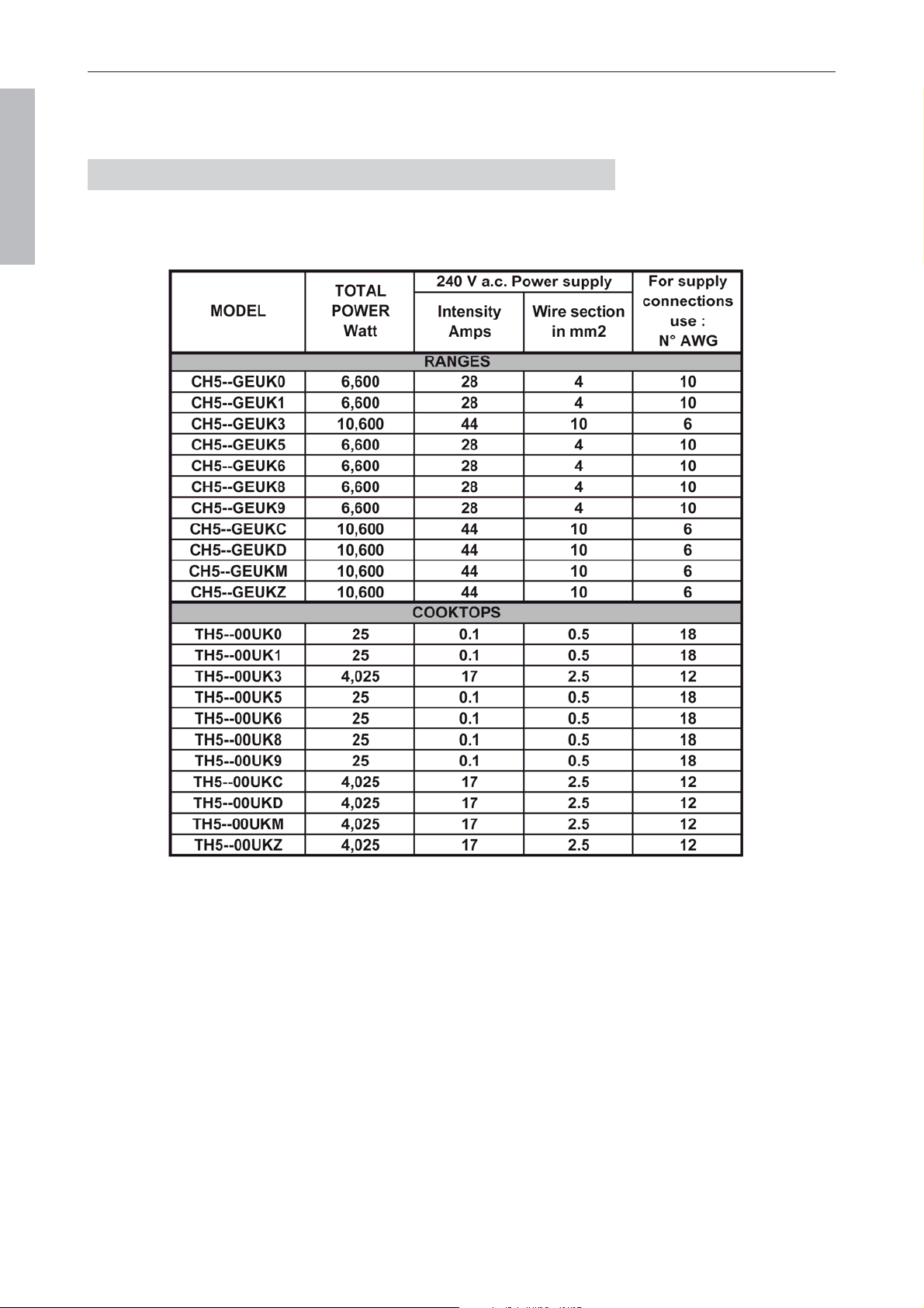
For each gas type and for each model, the tables below summarize the total electric power (W) and the gas
input ratings (BTU/hr).
ELECTRIC SUPPLY INFORMATION

DESCRIPTION Le Château
®
150
Page 21
LA CORNUE
Installation Guide Centenaire
08NOTINSTAL100/USA-8
USA & CANADA
GAS SUPPLY INFORMATION
Le Château
®
120 DESCRIPTION
2 gas burners (small burner at the rear)
1 small gas hotplate
1 reversible gas snack griddle
2 round electric plates
EZ
2 gas burners (small burner at the rear)
1 gas hotplate
2 gas burners (small burner at the rear)
E0
2 gas burners (small burner at the rear)
1 small gas hotplate
2 gas burners (small burner at the rear)
1 gas lava rock grill
E6
The ”Le Château 120” range, one of the models of the ”La Cornue” series consists of:
— 2 thermostatically-controlled small vaulted ovens, gas and electric (only ranges).
— One cooktop bounded at the rear by a stainless steel backsplash creating a gap between the
range and the wall, thus ensuring the removal of burnt gases and smells (ranges and cooktops).
4.
4.
D
D
ESCRIPTION
ESCRIPTION
”L
”L
E
E
C
C
HÂTEAU
HÂTEAU
®
®
120”
120”
Page 22
LA CORNUE
Installation Guide Centenaire
08NOTINSTAL100/USA-8
USA & CANADA
HOB CONFIGURATIONS
2 gas burners (small burner at the rear)
1 maxi burner
2 gas burners (small burner at the rear)
E1
2 gas burners (small burner at the rear)
1 small gas hotplate
2 gas burners (small burner at the rear)
1 reversible gas snack griddle
E7
2 gas burners (small burner at the rear)
1 gas hotplate
1 gas lava rock grill
E2
2 gas burners (small burner at the rear)
1 small gas hotplate
1 gas lava rock grill
2 round electric plates
EC
2 gas burners (small burner at the rear)
1 gas hotplate
1 reversible gas snack griddle
E3
2 gas burners (small burner at the rear)
1 gas hotplate
2 round electric plates
E4

DESCRIPTION Le Château
®
120
Ranges Cooktops
— Appliance height: 36” (914 mm) 7
7
/8” (200 mm)
— Height with backsplash: 38” (964 mm) 9
7
/8
” (250 mm)
— Width: 47
1
/4” (1,200 mm) 47
1
/4” (1,200 mm)
— Weight: 200 to 220 kg, 80 to 100 kg according to the models
(440 to 485 lbs) (176 to 220 lbs)
— Depth to the wall:
- Front: 26
1
/8” (665 mm)
- Rail: 31” (785 mm)
- Hob edge: 27
1
/2
” (700 mm)
Thickness: 1
5
/8” (40 mm)
Page 23
LA CORNUE
Installation Guide Centenaire
08NOTINSTAL100/USA-8
USA & CANADA
DIMENSIONS
Cooktop - model TH2
Range - model CH2
Le Château
®
120 DESCRIPTION
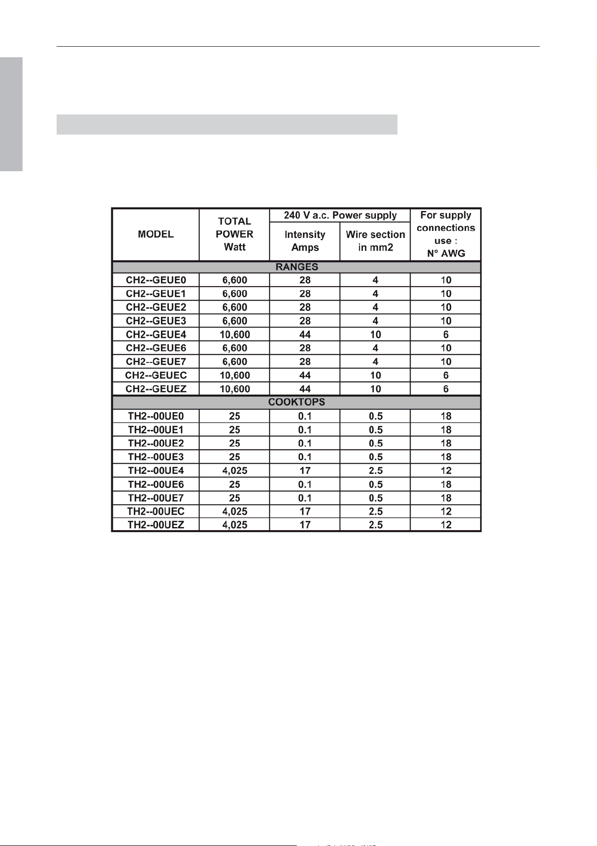
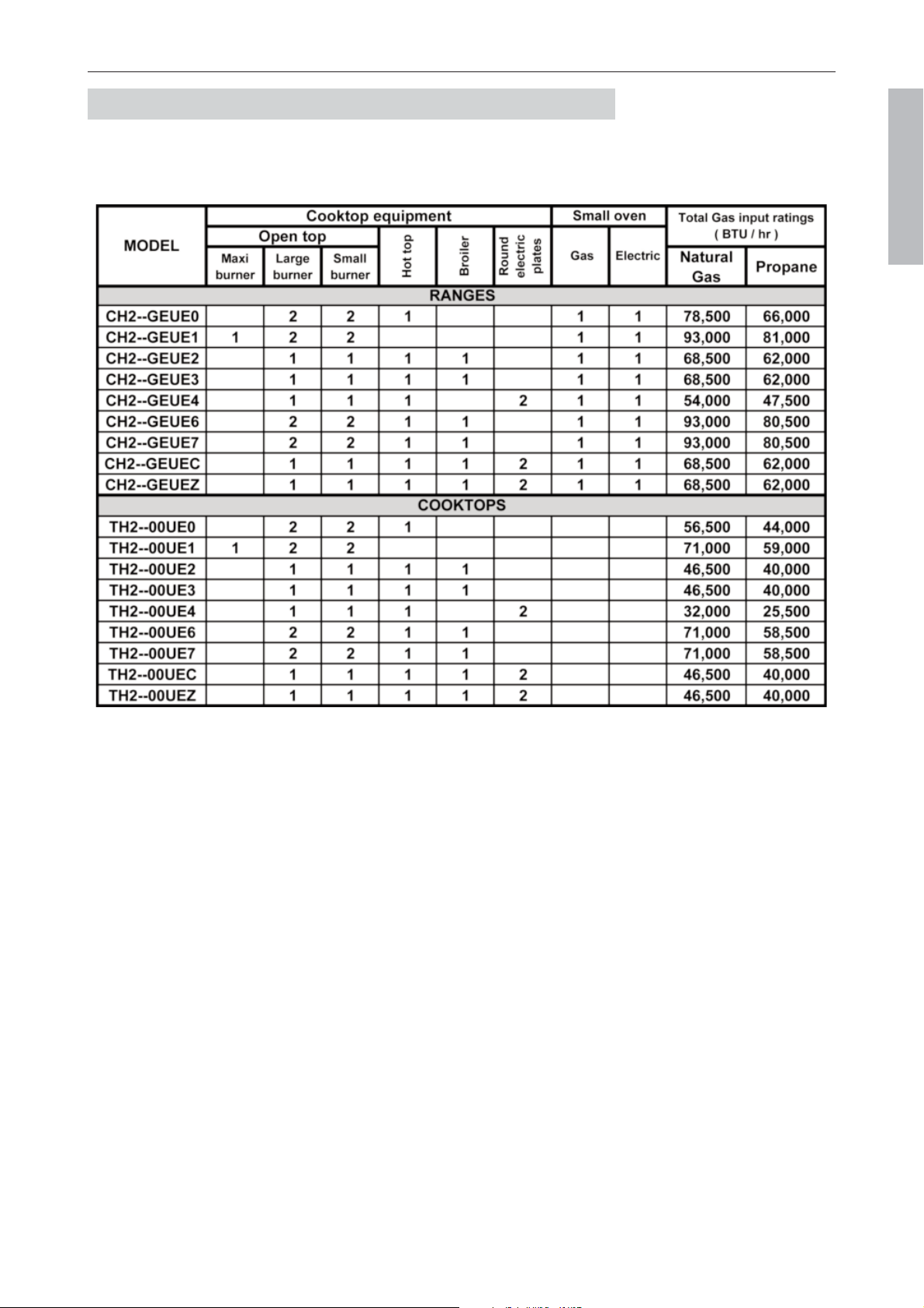
For each gas type and for each model, the tables below summarize the total electric power (W) and the gas
input ratings (BTU/hr).
Page 24
LA CORNUE
Installation Guide Centenaire
08NOTINSTAL100/USA-8
USA & CANADA
ELECTRIC SUPPLY INFORMATION
DESCRIPTION Le Château
®
120
Page 25
LA CORNUE
Installation Guide Centenaire
08NOTINSTAL100/USA-8
USA & CANADA
GAS SUPPLY INFORMATION
Le Château
®
90 DESCRIPTION
2 gas burners (small burner at the rear)
1 small gas hotplate
2 round electric plates
C5
Page 26
LA CORNUE
Installation Guide Centenaire
08NOTINSTAL100/USA-8
USA & CANADA
2 gas burners (small burner at the rear)
1 gas hotplate
C0
2 gas burners (small burner at the rear)
1 small gas hotplate
1 gas lava rock grill
C3
2 gas burners (small burner at the rear)
1 maxi burner
C1
2 gas burners (small burner at the rear)
1 small gas hotplate
1 reversible gas snack griddle
C4
2 gas burners (small burner at the rear)
1 small gas hotplate
2 gas burners (small burner at the rear)
C2
The ”Le Château 90” range, one of the models of the ”La Cornue” series consists of:
— 1 thermostatically-controlled large vaulted oven, gas or electric (only ranges).
— One cooktop bounded at the rear by a stainless steel backsplash creating a gap between the
range and the wall, thus ensuring the removal of burnt gases and smells (ranges and cooktops).
5.
5.
D
D
ESCRIPTION
ESCRIPTION
”L
”L
E
E
C
C
HÂTEAU
HÂTEAU
®
®
90”
90”
HOB CONFIGURATIONS
DESCRIPTION Le Château
®
90
Ranges Cooktops
— Appliance height: 36” (914 mm) 7
7
/8” (200 mm)
— Height with backsplash: 38” (964 mm) 9
7
/8
” (250 mm)
— Width: 35
1
/2” (900 mm) 35
1
/2” (900 mm)
— Weight: 100 to 150 kg, 70 to 100 kg according to the models
(220 to 330 lbs) (154 to 220 lbs)
— Depth to the wall:
- Front: 26
1
/8” (665 mm)
- Rail: 31” (785 mm)
- Hob edge: 27
1
/2” (700 mm)
Thickness: 1
5
/8” (40 mm)
Page 27
LA CORNUE
Installation Guide Centenaire
08NOTINSTAL100/USA-8
USA & CANADA
DIMENSIONS
Cooktop - model TC9
Range - model GC9
Le Château
®
90 DESCRIPTION
Page 28
LA CORNUE
Installation Guide Centenaire
08NOTINSTAL100/USA-8
USA & CANADA
For each gas type and for each model, the tables below summarize the total electric power (W) and the gas
input ratings (BTU/hr).
ELECTRIC SUPPLY INFORMATION
DESCRIPTION Le Château
®
90
Page 29
LA CORNUE
Installation Guide Centenaire
08NOTINSTAL100/USA-8
USA & CANADA
GAS SUPPLY INFORMATION
Le Château
®
75 DESCRIPTION
Page 30
LA CORNUE
Installation Guide Centenaire
08NOTINSTAL100/USA-8
USA & CANADA
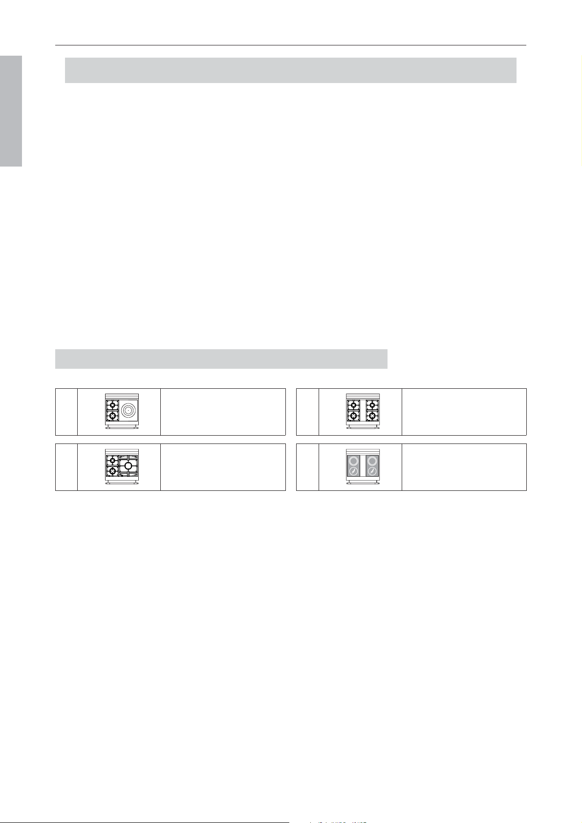
HOB CONFIGURATIONS
2 gas burners (small burner at the rear)
1 gas hotplate
B0
2 gas burners (small burner at the rear)
2 gas burners (small burner at the rear)
B2
2 gas burners (small burner at the rear)
1 maxi burner
B1
2 round electric plates
2 round electric plates
BA
The ”Le Château 75” range, one of the models of the ”La Cornue” series consists of:
— 1 thermostatically-controlled small vaulted oven, gas or electric (only ranges).
— One cooktop bounded at the rear by a stainless steel backsplash creating a gap between the
range and the wall, thus ensuring the removal of burnt gases and smells (ranges and cooktops).
6.
6.
D
D
ESCRIPTION
ESCRIPTION
”L
”L
E
E
C
C
HÂTEAU
HÂTEAU
®
®
75”
75”
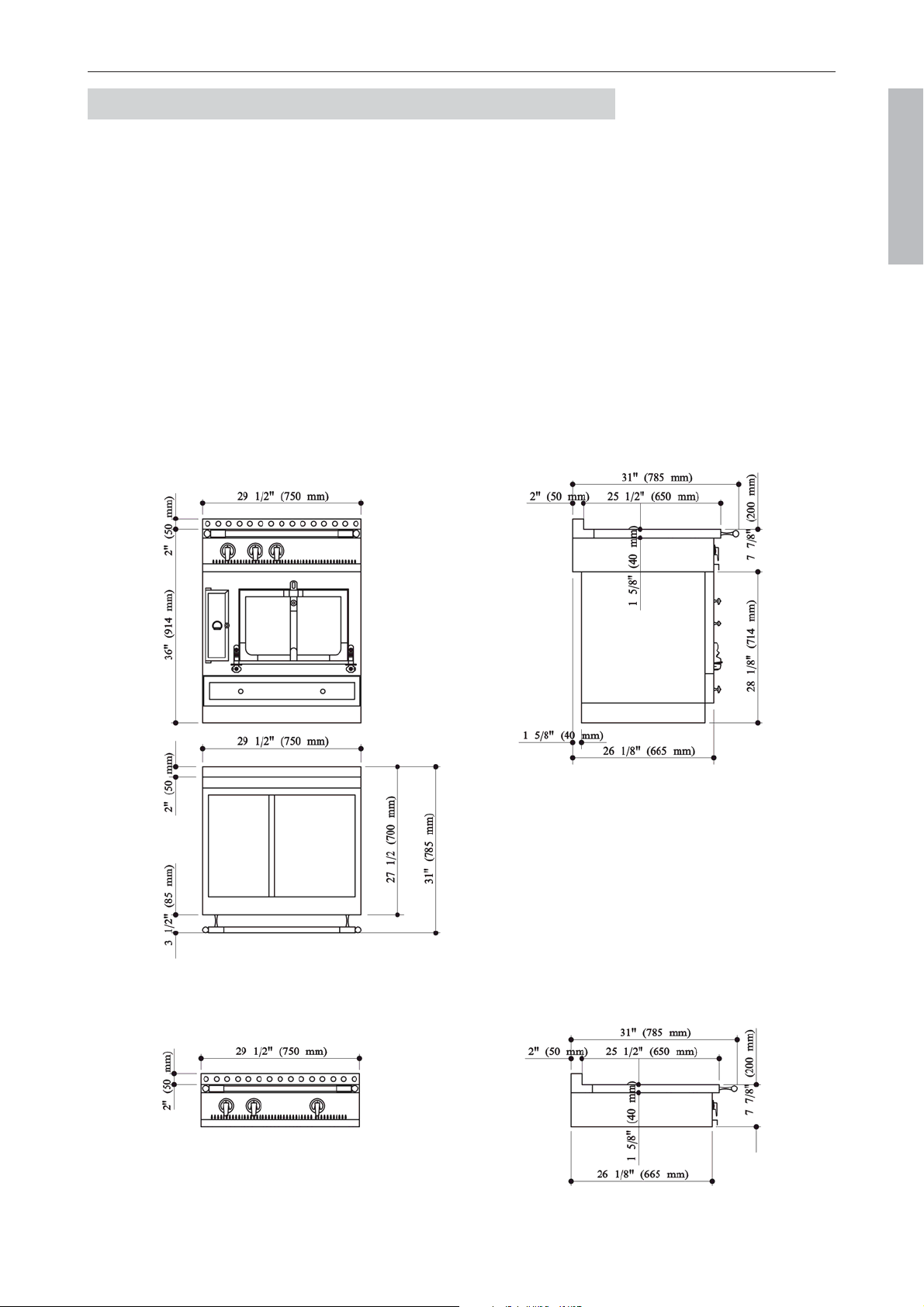
DESCRIPTION Le Château
®
75
Ranges Cooktops
— Appliance height: 36” (914 mm) 7
7
/8” (200 mm)
— Height with backsplash: 38” (964 mm) 9
7
/8
” (250 mm)
— Width: 29
1
/2” (750 mm) 29
1
/2” (750 mm)
— Weight: 100 to 130 kg, 60 to 80 kg according to the models
(220 to 286 lbs) (130 to 176 lbs)
— Depth to the wall:
- Front: 26
1
/8” (665 mm)
- Rail: 31” (785 mm)
- Hob edge: 27
1
/2” (700 mm)
Thickness: 1
5
/8” (40 mm)
Page 31
LA CORNUE
Installation Guide Centenaire
08NOTINSTAL100/USA-8
USA & CANADA
DIMENSIONS
Cooktop - model TA7
Range - model CA7
Le Château
®
75 DESCRIPTION
Page 32
LA CORNUE
Installation Guide Centenaire
08NOTINSTAL100/USA-8
USA & CANADA
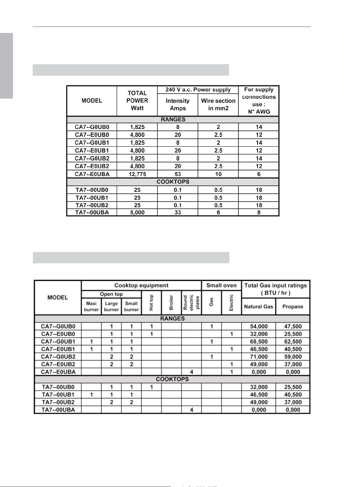
For each gas type and for each model, the tables below summarize the total electric power (W) and the gas
input ratings (BTU/hr).
ELECTRIC SUPPLY INFORMATION
GAS SUPPLY INFORMATION

Page 33
LA CORNUE
Installation Guide Centenaire
08NOTINSTAL100/USA-8
USA & CANADA
In order to be able to install your range or cooktop as soon as it is delivered, you must ensure that in your
kitchen, the gas and electrical supplies are ready for it.
1.1. Ventilation
The use of a gas cooking appliance results in the production of heat and moisture in the room in which it
is installed. It is essential that the kitchen where the ”La Cornue” stove will be installed has excellent ven-
tilation to the outside, for vapor and combustion gases, and a fresh air inlet.
Do not use air recycling systems.
Ventilation exhaust devices can be vapor aspirators or hoods.
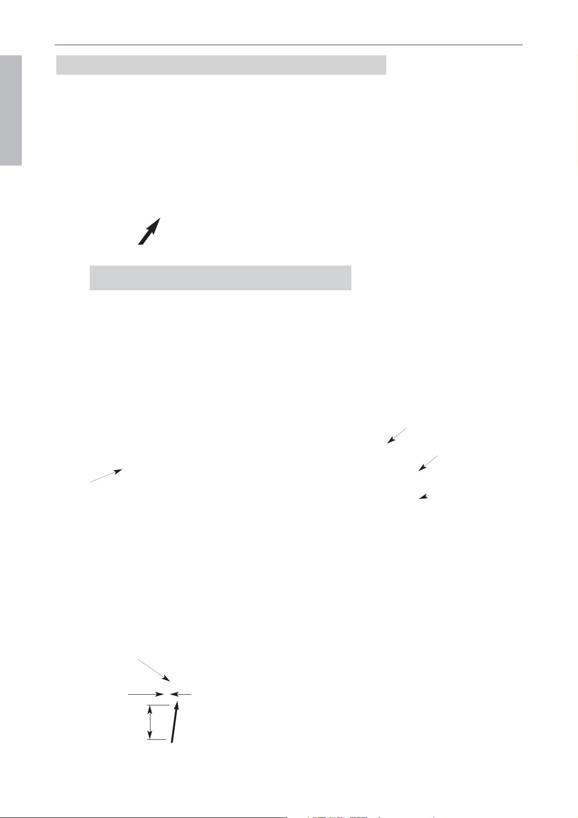
1.2. Clearances to combustible construction
The minimum horizontal distance from
sides of appliance to the adjacent vertical
combustible walls extending 18” (457
mm) above the top panel is 12” (305
mm).
The maximum depth of overhead cabinets
is 13” (330 mm).
The minimum horizontal distances
between overhead cabinets is not less then
the nominal width of the appliance (A).
To eliminate the risk of burns or fire
by reaching over heated surface units,
cabinet storage space located above
the surface units should be avoided.
Any element, either an extraction hood or
cabinet, situated directly above the range
must be made of non-combustible material
and placed at no less than 30” (760 mm)
above range.
The recommanded height is 36” (914
mm) above range.
May be installed with zero clearance between adjacent combustible construction below the cooking surface and the back
and sides of the appliance.
We recommend to leave 1/2” gap on each side in order to allow enaugh space for moving the range.
To be used in conjonction with a suitable ventilation hood.
1. SAFETY REQUIREMENTS
B
B
EFORE
EFORE
DELIVERY
DELIVERY
I
I
N
N
S
S
T
T
A
A
L
L
L
L
A
A
T
T
I
I
O
O
N
N
INSTALLATION Before delivery
1/2” recommended 1/2” recommended
Clearances to combustible construction

Page 34
LA CORNUE
Installation Guide Centenaire
08NOTINSTAL100/USA-8
USA & CANADA
Electrical - Gas supply INSTALLATION
Voltage: 240 V a.c., single-phase, 3 wire system, 50/60 Hz
Safety: The range, when instal led must be electrical ly grounded in accordance with local
codes, or in the absence of local codes, with the latest edition of the National Electrical Code,
ANSI / NFPA 70 in the USA and the Canadian Electrical Code, CSA C22.2, in Canada as appli-
cable.
Power: Check the power rating at your electric meter (maximal load) to ensure that it is suitable
for your model, taking into account all other electrical appliances installed on the same
circuit.
The tables in pages 14, 17, 20, 24, 28 and 32 show the necessary power and amp ratings for
each La Cornue model.
The power of the ”La Cornue” stoves, does not al low for a simple plug and socket connection;
the electrical connection must be made by means of an adequate flexible cord, built-in junction
box, with terminal blocks; the box is located about 12” (300 mm) from the floor, on the wall
behind the stove, on the right.
Use sealing compound on all pipe joints. Compound used must be resistant to the action of LP Gases.
The gas supply line to the appliance must be at least the same size as the gas inlet. An easily accessible
manual shutoff valve must be installed, keeping in mind the fact that on the appliance, the gas inlet is
located:
- On the left-hand side of the appliance, approximately 2
1/2
” (60 mm) from the edge.
- 24” (620 mm) above the floor (for the ranges).
NOTE:
Make sure that the supply line is clear of burrs and metal particles in order to avoid damage to the
gas controls once the gas is turned on. The pipe connections can then be made
When your ”La Cornue” appliance is installed between kitchen cabinets, the manual shutoff valve should
be accessible. We recommend it be located at the rear of an adjacent cabinet.
According to gas regulations, any opening in the wall or on the floor for gas supply of the appliance must
be properly sealed as well as any circulation of air between the gas supply room and the kitchen.
When all the work has been carried out on your gas supply network, ensure that no metallic burr can
enter the supply tube of the stove and block the burners. Then make sure that all gas connections are pro-
perly sealed. Refer to page 43 for initial test of the unit prior to turning the gas on. Refer to ”Important
Safety Information” section, on pages 1 - 8.
In order to ensure that the range is perfectly horizontal, especially in a kitchen with old paving or floo-
ring, we recommend that you install the stove on a wooden or cement base, the height of which will bring
the hot top to a level in accordance with its environment or your requirements.
We recommend a base of the exact size of the stove base.
4. INSTALLATION
3. GAS SUPPLY
2. ELECTRICAL SUPPLY

Page 35
LA CORNUE
Installation Guide Centenaire
08NOTINSTAL100/USA-8
USA & CANADA
INSTALLATION Handling instructions
Anti-Tip Device (only Château 90 & Château 75 models)
WARNING
Ranges Château 90 and Château 75 must be secured by Anti-Tip bracket supplied. See instructions to ins-
tall (supplied with bracket). Unless properly installed, the range could be tipped by leaning on the door.
Injury might result from spilled hot liquids or from the range itself.
The following instructions are to be fol lowed by qualified personnel, trained to hand le extremely
heavy loads. Usually, a single-oven cooker can be lifted by two people, a double-oven cooker is best
hand led by at least four people.
1. In order to lighten the cooker, remove and set aside the drawers, the drip-trays, the backsplash, the
handrail, the oven accessories, the pan supports, the solid top and any other accessories.
2. Remove oven doors by engaging the latches on the hinges and by pulling the door back and up.
3. Remove the plinthes/toe-kicks using a standard screwdriver.
H
H
ANDLING
ANDLING
INSTRUCTIONS
INSTRUCTIONS
Complete cooker
Full view of elements set aside.

Page 36
LA CORNUE
Installation Guide Centenaire
08NOTINSTAL100/USA-8
USA & CANADA
Handling instructions INSTALLATION
4. Create a harness with four Installer’s straps.
5. Twist the harness and tilt the cooker to place the harness.
6. When lifting up stairs, the straps of the handlers at the bottom should be shorter so the cooker stays
level.
The back of the cooker should always face the inside side of the ramp.
Lighten cooker
INSTALLATION Assembly instructions
Château cookers are equipped with adjustable legs so the height of the cooktop can vary from 910 mm
(35.82 in) to 920 mm (36.22 in).
Remove the drawers and plinthes/toe-kicks, set the cooker in place, screw up the central legs so the cooker
rests on the outside legs and adjust the height.
Once the cooker is resting at the right height and is level, screw down the central legs to balance the
weight.
A
A
SSEMBLY
SSEMBLY
INSTRUCTIONS
INSTRUCTIONS
1. HANDRAIL INSTALLATION
2. RISER / BACKSPLASH INSTALLATION
3. HEIGHT ADJUSTMENT
13 mm
8 mm
Support
Plate
M8x20
M8x20
Support
Plate
M5x16
Washer
Inserts
Page 37
LA CORNUE
Installation Guide Centenaire
08NOTINSTAL100/USA-8
USA & CANADA
Page 38
LA CORNUE
Installation Guide Centenaire
08NOTINSTAL100/USA-8
USA & CANADA
Gas chimney protection plate comes separately in the package and needs to be installed above the flue
channel behind the gas oven.
This appliance must be instal led by a qualified professional in accordance with the current
regulations in the country where the appliance is instal led.
Remove al l packing material and literature from oven before connecting gas and electrical
supply to range.
C
C
ONNECTIONS
ONNECTIONS
Electrical
connection
Terminal Block
Gas Inlet Male
1/2 NPT connection
Rear view Ranges:
Château 90 and Château 75
24“ (620 mm)
2 1/2“ (60 mm)
Electrical
connection
Terminal Block
Gas Inlet Male
1/2 NPT connection
Rear view Ranges:
Grand Palais 180, Château 165, Château 150 and Château 120
24 “ (620 mm)
2 1/2“ (60 mm)
Side view
All Ranges
Gas Inlet Male
1/2 NPT connection
Assembly instructions INSTALLATION
4. GAS CHIMNEY PROTECTION INSTALLATION
Gas oven chimney protection2 x Screw M5 x 16 mm + washer
10 1/2” (265 mm)
Protection Plate
Opening Size 4 3/4” x 7 1/4” (120 x 185 mm)
Gas oven chimney protection
Page 39
LA CORNUE
Installation Guide Centenaire
08NOTINSTAL100/USA-8
USA & CANADA
INSTALLATION Electrical connection
The nameplate label of your appliance is on the bottom-left, on
the toe kick behind the storage drawer, or inside the spill tray for
the Château 120 models and for the standalone cooktops. To see
this rating plate, pull out the storage drawer or spill tray.
You will find on this plate the name and address of the
manufacturer as well as the following information:
1) Kind of appliance (Model )
2) Serial number (order number)
3) Manufacturing date
4) Total gas rating BTU/hr
5) Type of gas and Manifold pressure
6) Burner input rating BTU/hr for each burner
7) Voltage rating in Volt, Total Electric Power in Watts and Intensity (Amps)
The appliance must be electrical ly instal led and grounded in accordance with local codes or in the
absence of such codes with the latest edition of the ”National Electrical Code”, ANSI/NFPA 70 in
the USA, and CSA C22.2 ”Canadian Electrical Code” - in Canada.
Disconnect al l the power supply circuits before accessing the junction boxes.
This appliance must be supplied with 240 Volt and 60 Hz frequency, and connected to an individual,
properly grounded branch circuit, protected by a circuit breaker or time-delay
fuse, as noted on the rating plate.
Use only a 3-wire or a 4-wire UL-listed power-supply cord rated 120/240 Volts
with a straight terminals and marked for use with ranges.
The specified ampere rating for the cord shall be 30, 40, or 50 A, in accordance
with Table below:
Only a 4 wire cord is to be used when the appliance is installed where grounding through the neutral
conductor is prohibited, such as:
- new branch-circuit installations (1996 NEC),
2. ELECTRICAL CONNECTION
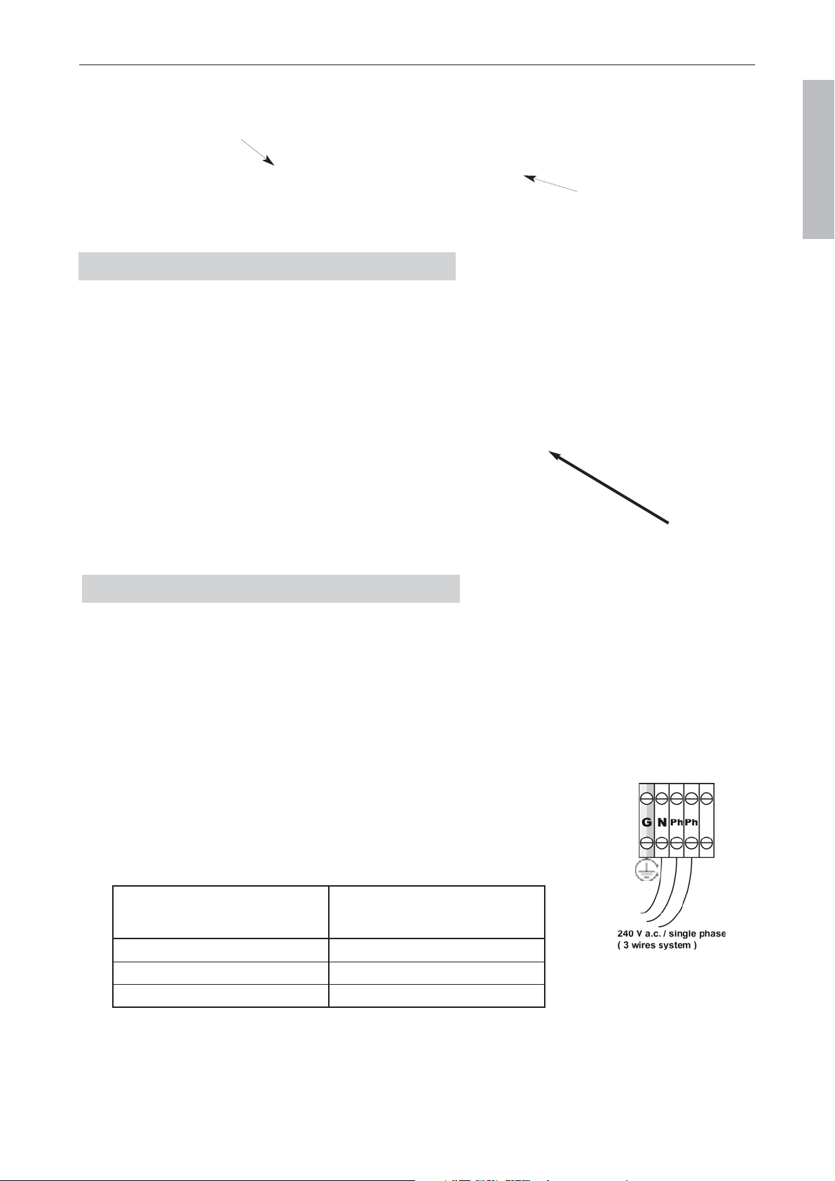
G-Ground N-Neutral
Ph-Phase
Electrical
connection
Terminal
Block
Gas Inlet Male
1/2 NPT connection
1 1/2“ (40 mm)
7 5/8“
(195 mm)
Rear view All Cooktops
1. NAMEPLATE LABEL
Range rating,
W
120/240 V 3-wire
Specified rating of
power-supply-cord kit
A
0 – 8,749 30
8,750 – 16,500 40
16,501 – 22,500 50

Page 40
LA CORNUE
Installation Guide Centenaire
08NOTINSTAL100/USA-8
USA & CANADA
Electrical connection INSTALLATION
- mobile homes,
- recreational vehicles or
- in an area where local codes prohibit grounding through the neutral.
The power of the electric elements for each appliance see page 11 and pages 12 - 34.
The overall wattage of your appliance is also indicated on the nameplate label and on the warranty
certificate (See item 1 page 41 for the location of the nameplate label).
Wiring must conform to National Electric Codes.
If the electric service provided does not meet the above specifications, have a licensed electrician install an
approved outlet.
Because range terminals are not accessible after range is in position, flexible service conduit or cord must
be used at least 4 ft (1.2 m) length. The range can then be easily disconnected for servicing.
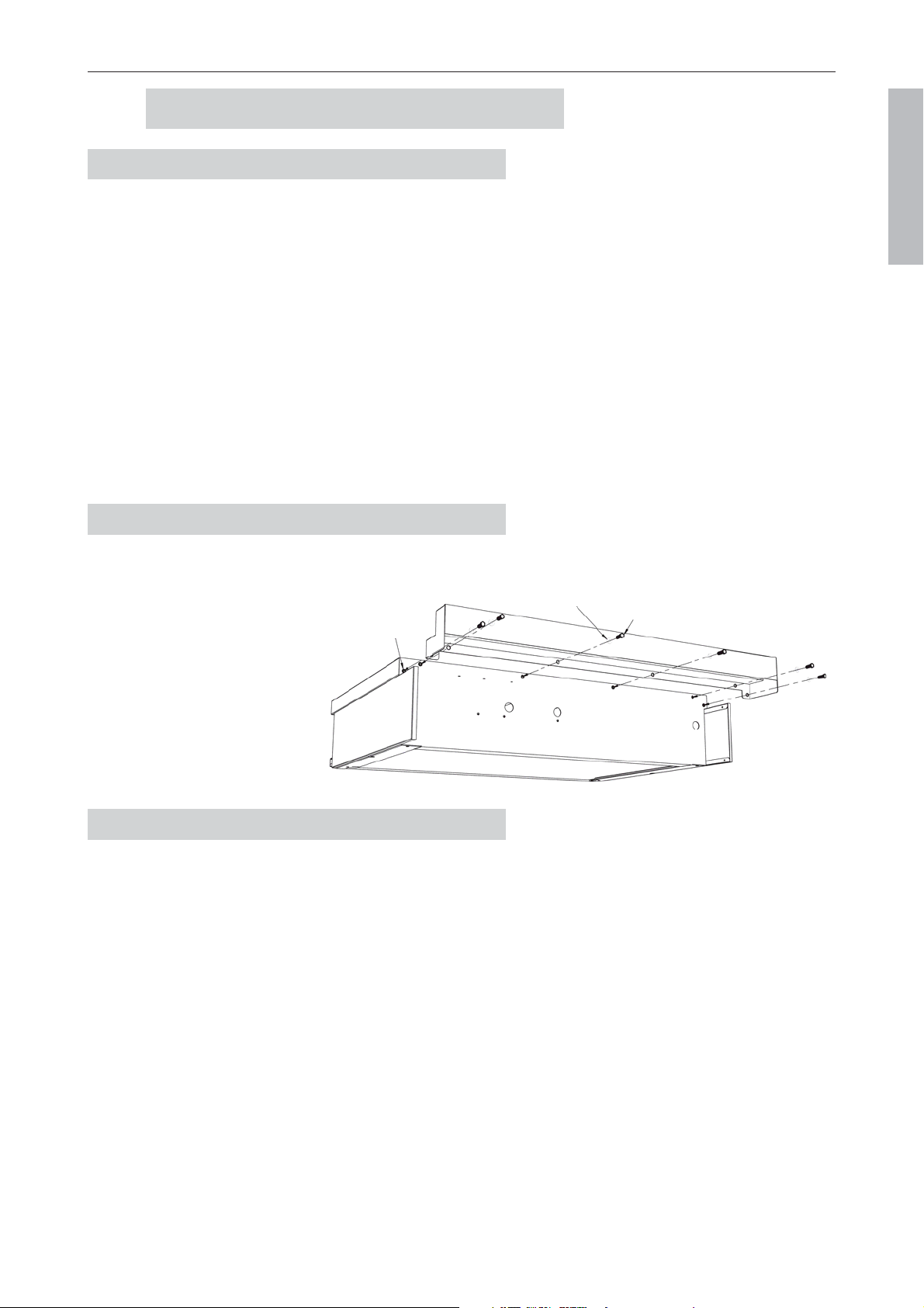
The ”La Cornue” appliance is supplied with a connection terminal block accessible by unscrewing the
stainless steel protection plate on the backside.
1. Remove the screws and the protection plate on the backside of the ranges.
For the cooktops remove the cover of the main terminal box.
2. Now the terminal block is accessible
3. The appliance is shipped with a strain relief device to secure power cord. Insert the power cord through
the strain relief and tighten it.
Ranges
Terminal
block
Cooktops
Ranges
Cooktops

Page 41
LA CORNUE
Installation Guide Centenaire
08NOTINSTAL100/USA-8
USA & CANADA
INSTALLATION Gas connection
4. Insert the strain relief device into the hole and push it to the left. Tight up the power cord and strain
relief device with the screw.
5. Install the power cord: attach the wires to the termi-
nal block as follows:
- neutral (white wire) to N,
- the L1 and L2 (red and black wire) to P1 and P2,
- the ground to T (yellow / green).
NOTE: Make sure the wires are completely inserted
into the terminals and secure connections are made.
6. Re-install the protection plate for the range or the cover for the cooktop.
7. Make sure that everything is properly secured.
R
EMINDER: connections to main power supply preferably suppose to be hardwired into the wall Junction Box
compare using the Plugs and Outlet.
Fix the cable well below the hot air out lets, at the rear of the oven, never in front of them.
The instal lation of your La Cornue appliance must conform with local codes or, in the absence of local
codes, in the USA with the ”National Fuel Gas Code”, ANSI Z223.1, latest edition, and, in Canada,
with CAN/CGA - B149.1, and CAN CGA - B149.2, ”Instal lation Code for Gas Burning Appliances”.
In The Commonwealth Of Massachusetts
This product must be instal led by a licensed plumber or gas fitter when instal led within the
Commonwealth of Massachusetts.
A ”T” hand le type manual gas valve must be instal led in the gas supply line to this appliance.
All La Cornue ranges and cooktops are fully assembled and equipped for use with the type of gas shown
on the rating plate of the appliance.
If no special instructions were mentioned upon ordering, the stove is fitted with orifices for natural gas.
Prior to installation, ensure that the local distribution conditions (nature of the gas and gas
pressure) and the adjustment of the appliance are compatible.
The range is designed to operate at a manifold pressure of 5” of Water Column (1,24 kPa = 12,4 mbar) on
natural gas, or a manifold pressure of 11” of Water Column (2,74 kPa = 27,4 mbar) on LP gas (Propane).
3. GAS CONNECTION

Page 42
LA CORNUE
Installation Guide Centenaire
08NOTINSTAL100/USA-8
USA & CANADA
If the range is to be used on LP gas, a qualified LP installer must convert it. We recommend that the range
be converted before installation.
For proper operation, the pressure of natural gas supplied to the regulator must be between 6” and
10” of water column (1,49 and 2,49 kPa).
For LP gas, the pressure supplied must be between 12”
and 13” of water column (3 and 3,24 kPa).
When checking for proper operation of the regulator,
the inlet pressure must be at least 1” (0,25 kPa) greater
than the operating (manifold) pressure as given above.
The pressure regulator located at the inlet of the range
manifold must remain in the supply line regardless of
whether natural or LP gas is being used.
A flexible metal appliance connector used to connect
the range to the gas supply line should have an I.D. of
½” and be 5 feet (1,5 m) in length for ease of installation.
The gas regulator on the appliance is set at the factory
for pressures given by regulations.
For the La Cornue ranges and hobs the regulator and the pressure tap can be found on the hob’s manifold
located by the 2 left gas burners
Connect the Range to the Gas Supply
Shut off the main gas supply valve before disconnecting the old
range and leave it off until the new hookup has been completed.
Don’t forget to relight the pilot on other gas appliances when you
turn the gas back on.
Because hard piping restricts movement of the range, the use of a
CSA International certified flexible metal appliance connector is
recommended unless local codes require a hard piped connection.
Never use an old connector when installing a new range. If the hard
piping method is used, you must carefully align the pipe; the range
cannot be moved after the connection is made. To prevent gas leaks,
put pipe joint compound on, or wrap pipe thread tape with Teflon* around, all male (external) pipe threads.
*Teflon: Registered trademark of DuPont
Install a manual gas line shut-off valve in the gas line in an easily accessed location outside of the range.
Make sure everyone operating the range knows where and how to shut off the gas supply to the range.
Connect flexible metal appliance connector to the adapter on the range. Position range to permit
connection at the shut-off valve.
When all connections have been made, make sure all range controls are in the off position and turn on the
main gas supply valve.
Use a liquid leak detector at all joints and connections to check for leaks in the system.
Use a product specifically manufactured for leak detection. Leak testing of the appliance shall be
conducted in accordance to the manufacturer’s instructions.
Gas connection INSTALLATION
Male threaded fitting,
thread 1/2 NPT
Pressure
regulator
Pressure
test point
Page 43
LA CORNUE
Installation Guide Centenaire
08NOTINSTAL100/USA-8
USA & CANADA
The burners on the stoves of the ”La Cornue” line are fitted with safety thermocouples: should a burner
extinguish, the gas supply to this burner is automatically cut off.
Upon initial test of unit
When first testing the gas operated burners, you may find they do not operate. This is normal, and
is caused by air in the gas lines. Simply, operate each burner starting with the top burners, until all
the air is displaced by the gas and ignition will result. This may take 1 to 5 minutes.
On first use, the electronic safety device of the gas oven may switch on (the red indicator light goes
on).
Please press the reset button (B) until air is also displaced in the oven and the flame goes on.
1. TESTS
O
O
P
P
E
E
R
R
A
A
T
T
I
I
O
O
N
N
OPERATION Test
The appliance must be connected to the type of gas shown on the rating plate of the
appliance.
The gas supply line must be at least a 1/2 inch pipe.
On al l pipe joints use sealing compound that does not react to propane gas.
Check gas leaks by using a liquid leak detector.
Do not use an open flame
INSTALLER
Leave this manual with the appliance and advise the cus-
tomer to keep it for future reference.
Inform the consumer of the location of the
gas shut-off valve.
Note: Propane gas cylinders must never be
located inside your home.
2.1. Electric Oven
— Check ”oven / baking stone” selector (E) is on the ”oven”
position (to the left).
— Set the oven thermostat (F) to the desired temperature
setting. The green indicator light goes on.
After use, turn thermostat to ”0”.
2.2. Baking stone fonction (sold separatly):
The ”baking stone” option includes:
an oven-proof stone, a 3,000 Watt electric element and a
”bread server”.
To turn on your ”baking stone”, follow these
instructions:
- Remove the socket cover at the back of the oven
meant to receive the ”baking stone” electric
element.
- Plug the heating element in its socket.
- Place the grill-tray on the second shelf-level,
then place the stone on the grill.
- Preheat the oven by turning the selector (E) on
the ”oven” position (to the left) and the thermostat
(F) to about 440°F (230°C). After 15 to 20 minutes
preheating, turn the selector to the right on the
”baking stone” position and begin to bake.
or
- Turn the selector (E) on the ”baking stone” position (on the right) and turn the thermostat (F) to the
desired temperature.
- After 10 to 15 minutes of pre-heating (depending on the desired temperature), you may begin to bake.
After use, turn thermostat to ”0”.
After cooking on the stone, let in cool down in the oven, then remove the stone and the heating element from
the oven and place the cover back on the socket at the back of the oven.
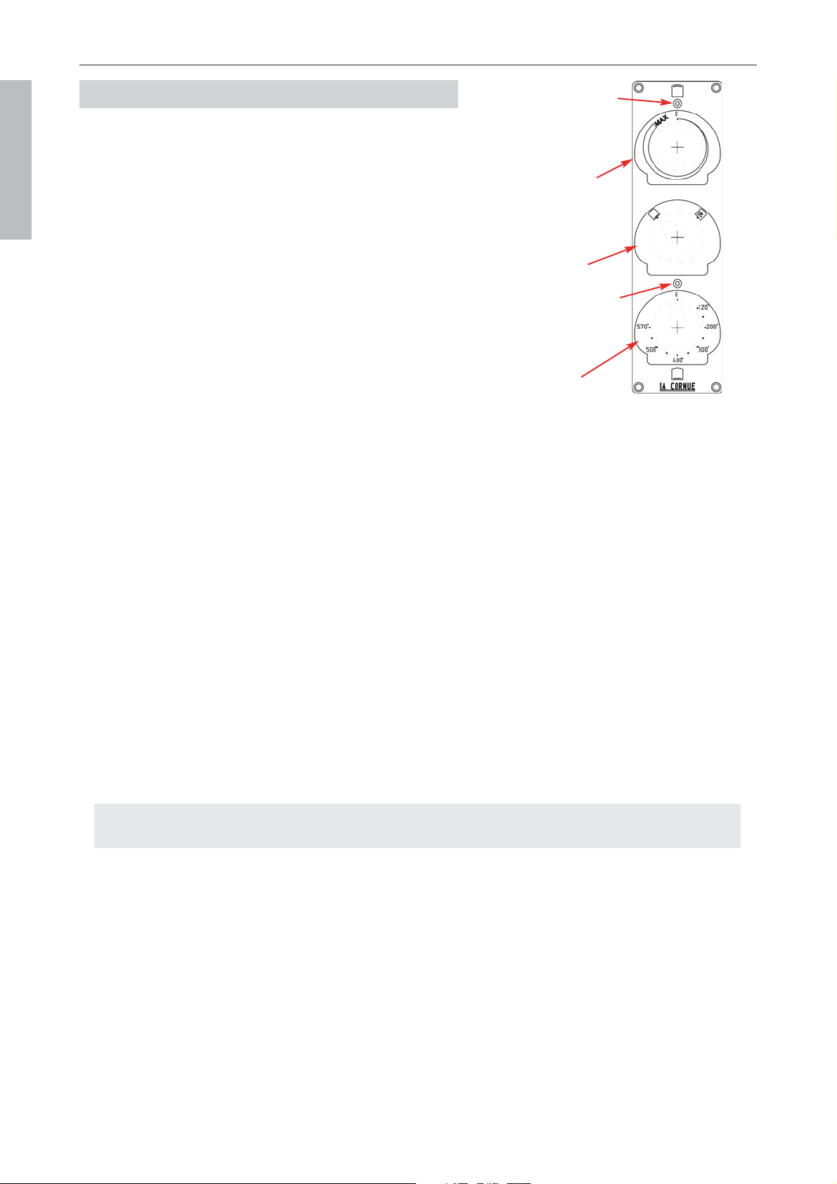
2.3. Electric broiler (gas or electric oven)
- The level of the broiler is controlled by the upper knob (D). The green indicator light goes on.
After use, turn knob to ”0”.
2.4. Gas oven with electronic ignition
Turn the thermostat knob (A) to the desired temperature setting. The green indicator light goes on.
The electronic control provides a fully automatic thermostatic temperature control. During this
process, it is normal that the flame will be totally shut on and off.
After use, turn thermostat to ”0”.
Page 44
LA CORNUE
Installation Guide Centenaire
08NOTINSTAL100/USA-8
USA & CANADA
Ovens OPERATION
WARNING: The baking stone and heating element are hot when functionning
and after use. Do not touch before they have cooled.
F
D
E
Electric broiler
control
Electric oven
thermostat
Oven / baking stone
selector
oven
baking
stone
Green indicator
Green indicator
stone
cover
socket
heating
element
second
level
2. STARTING WITH THE OVENS

Page 45
LA CORNUE
Installation Guide Centenaire
08NOTINSTAL100/USA-8
USA & CANADA
OPERATION Cooktop
Note: The red light (C) at the bottom of the control panel
indicates a problem in the ignition process. Whenever it goes
on, please check that gas is flowing into the appliance, reset by
pressing the ”B” button.
2.5. The oven dishes
There are several different trays in your oven:
The large tray or the pastry tray with an enamelled coating.
This is intended exclusively for pastry-making or for ingre-
dients to be grilled under the gas or electric oven grill.
The large size of this tray means that it can be used as a
cooking tray itself but is generally used for very large pieces of
meat. You should not use it to cook poultry or small roast.
The large roasting rack allows for the following:
- to place a roast in a terra cotta dish to sit on the roasting rack
in the large tray. Therefore, by using this system one makes
the most of the natural air convection, allowing for
the air flow to travel round and under the food.
- to place to roast directly onto the roasting rack in
the large tray. The roast will remain seasoned as well
as remaining medium rare or rare if you desire.
By using the ”spit” concept, the hot air envelopes the
entire piece of meat regardless of its size.
The ”shelf” tray acts as a support for all trays
which are used in this oven.
The large roasting dish in porcelain (one dish per
stove).
2.6. Instal lation of the ”shelf” tray
The sliders of the oven and the ”shelf” tray are supplied with stops in order to avoid taking away the shelves
inadvertently; these shelves can be removed and replaced easily.
Setting up of the ”shelf” tray
Before using your oven in complete safety, you must set up
correctly the shelves trays. To position the shelf tray at the
requested height, put it above the lateral oven slider (stops
at the back). Then push the tray to the very back of the
oven until the stops are positioned behind the sliders.
Pull the shelf tray until the back of the tray is blocked by
the stops of the lateral oven sliders.
Taking away the ”shelf” tray
Push the shelf tray which is on the sliders to the back of the oven; lift the back of the tray so the stops are
positioned above the sliders, then pull the tray towards you.
Green indicator
D
A
B
Gas oven
thermostat
Safety indicator
light (red)
Safety reset
button
C
Electric broiler
control
Green indicator
stops

Page 46
LA CORNUE
Installation Guide Centenaire
08NOTINSTAL100/USA-8
USA & CANADA
Important Information MAINTENANCE
3.1. Open tops, hot tops, open top broiler or gridd le with electronic ignition
To ignite the gas burner: press the control knob and rotate it counter clockwise,
to the ”big flame” position. The gas at the burner ignites automatically. Keep the
knob pressed in for 5 to 10 seconds, or longer if necessary (up to 30 seconds on
new equipment).
The sparking noise means that the ignition system is operating normally.
- Low setting: this is achieved by rotating the knob fully counter clockwise
(small flame).
- Shutoff: bring the knob back to its vertical position by rotating it to the right.
3.2. Round electric plates
Depending on models, your cooking appliance may be equipped with an element
with 2 round electric plates with a diameter of 18 cms for one and 20 cms for the other.
The round electric plates are made out of cast iron and are controlled by the knob
located on the front of the cooktop.
Their total electrical output is 4,000 Watts (13,600 BTU’s).
The knob have 3 marked positions ranging from warm (number 1) to very hot (number 3).
The largest of the two plates is the most powerful and is the one we suggest using
when cooking with large pans.
This section applies only for authorized service personnel recommended by
your dealer
u Keep appliance area clear and free from combustible materials, gasoline and other flammable vapors
and liquids.
u Do not obstruct the flow of combustion and ventilation air
u Contact the factory representative to perform maintenance and repairs.
u Clean appliance regularly, including special oven surfaces, with recommended cleaning agents.
u Disconnect power supply to the range before servicing.
I
I
MPORTANT
MPORTANT
INFORMATION
INFORMATION
M
M
A
A
I
I
N
N
T
T
E
E
N
N
A
A
N
N
C
C
E
E
3. STARTING WITH THE COOKTOP ELEMENTS
IMPORTANT
This equipment is design-certified by a National ly Recognized Testing Laboratory to the
appropriate National Standards as indicated on the Equipment Rating Plate.
Any modification without written permission of the La Cornue Company voids the
certification and warranty of this equipment.
Page 47
LA CORNUE
Installation Guide Centenaire
08NOTINSTAL100/USA-8
USA & CANADA
MAINTENANCE Adjustments
Open top, hot top, open top broiler or gridd le
Only the low settings for the burners of the open tops, hot top, open top broiler or griddle can be adjusted
by means of the following procedure:
1. Turn gasburner on and set to lowest setting (small flame).
2. Remove the control knobs (A) and knob bezel by
unscrewing the allen screw to access the by-pass screw.
3. Rotate the by-pass screw on the valve body to the left to
increase the flow rate, to the right to reduce it.
Only for natural gas reduced flow rate can be adjusted.
For the propane gas tighten the screw down.
Make sure that the resulting flame, at the lowest setting, is
sufficiently strong to heat the thermocouple.
4. Place back control knob bezel and control knob and proceed with testing.
Caution:
Make sure that there is a sufficient gap between the knobs and the
front panel, since it is necessary to ful ly depress the knob before rotating it
when igniting the burners.
Caution: Before proceeding with the conversion, shut off the gas supply to the appliance prior to
disconnecting the electrical power.
The orifices size depends on the type of gas. The table below is provided for you to determine which orifice
should be used if the type of gas is changed.
1. ADJUSTMENTS OF THE TOP BURNER LOW FLAME SETTINGS
2. FUEL CONVERSION
by-pass screw
A

Page 48
LA CORNUE
Installation Guide Centenaire
08NOTINSTAL100/USA-8
USA & CANADA
Fuel conversion MAINTENANCE
The location of the orifices for the various gas burners differ (see photographs below).
Note: Gas pressure regulator setting must also be adjusted when changing fuel type.
Orifices of gas burner and hotplate are replaced by means of this sequence:
1. Remove the brisk heat grill, then the pan.
2. Remove the cap of the burner.
3. Unscrew the orifice from the top using a standard 7 mm box spanner. Install the new orifice and
screw it down completely.
4. Place the cap of the burner taking care to place it correctly on the body of the burner.
5. Place the pan, then the grill or the fire plate.
The orifices for gas oven, open top broiler or griddle are always replaced in the following sequence:
1. Screw the adjusting cone (2) and insert it into the mixing tube in order to free sufficient space
for unscrewing the orifice.
2. Unscrew the orifice (1) with a 7 mm flat wrench.
3. Install the orifice (1) corresponding to the new type of gas and tighten it.
4. Ignite the burner and adjust the air inlet by screwing or unscrewing the adjusting cone (2) until
you obtain a slightly blue flame showing no separation; separation of the flame is an indication that
there is too much air.
5. Then block the adjusting cone (2) with the blocking washer (3).
Once you have changed the injectors, it is a good idea to adjust the low settings for the hob burners (see
Section 1).
open top broiler or griddle
gas burner
gas oven
orifice
cap of the burner
2
1
1
3
3
2

Page 49
LA CORNUE
Installation Guide Centenaire
08NOTINSTAL100/USA-8
USA & CANADA
Save the orifices removed from the appliance for future use.
If the range is to be used above 3000ft the burner orifices must be changed. This conversion must be
performed by a qualified gas installer.
Read the instructions before converting this appliance.
Failure to convert the appliance correctly could invalidate any warranty or liability claims and lead to
prosecution.
When servicing or replacing gas-carrying components disconnect from gas before commencing operation.
Use the correct orifices for high altitude given by La Cornue service only for your appliance.
When you have completed the changes, check the appliance is gas sound.
CAUTION: DO NOT USE A FLAME TO CHECK FOR GAS LEAKS.
Do not use re-conditioned or unauthorized gas controls.
Save the orifices removed from the appliance for future use.
Check operation of all the burners.
After conversion the installation must comply with the relevant regulations and also the local electricity
supply company requirements.
Remove the brisk heat grill (A), the cap of the burner (B), then the pan (C). The regulator is now accessible.
The regulator has a bayonet mounted top cap. Using a small coin press in and turn the cap to remove it.
Turn the cap over so that the letters ”LP” (for propane gas) or ”NAT” (for natural gas) are visible on base
of the hollow in the cap. Replace the cap making sure that the bayonet pins are securely located
MAINTENANCE Gas Pressure Regulator
WARNING
The conversion kit shall be installed by a qualified service
agency in accordance with the manufacturer's instructions and
all applicable codes and requirements of the authority having
jurisdiction. If the information in these instructions is not follo-
wed exactly, a fire, explosion or production of carbon monoxi-
de may result causing property damage, personal injury or loss
of life. The qualified service agency is responsible for the pro-
per installation of this kit. The installation is not proper and
complete until the operation of the converted appliance is chec-
ked as specified in the manufacturer's instructions supplied
with the kit.
4. GAS PRESSURE REGULATOR
3. CONVERTING FOR HIGH ALTITUDE

Page 50
LA CORNUE
Installation Guide Centenaire
08NOTINSTAL100/USA-8
USA & CANADA
Stick on label
Stick the appropriate label on to the data badge to indicate the gas the appliance is now set for.
Pressure Testing
Connect the appliance to the gas supply. Check the appliance is gas sound.
The gas pressure can be measured at the pressure test point on the appliance side on the manifold, near
the pressure regulator.
The light is located on the side at the top of the oven; it is
automatically switched on when the oven door is opened.
Please note: disconnect your stove before interfering with
the light to prevent any risk of an electrical shock and to
al low the appliance to cool down (if necessary).
Remove the protection glass and then unscrew the damaged
light.
Refit a new light and the protection glass.
Technical characteristics of the light:
- 25W - 230V - 240V
- 300°C - E14 base
Oven Light MAINTENANCE
Pressure
regulator
Pressure regulator
Pressure
test point
A
B
C
B
Cap
Natural Gas
Cap
LP Gas
5. REPLACING THE OVEN LIGHT
Your selection of LA CORNUE equipment is your assurance of quality and dependability that
reflects over 100 years of experience in manufacturing the finest gas cooking equipment.
You can always rely on your dealer and the Company to stand behind every product anywhere in
the U.S.A. and in Canada. For additional equipment, service and information contact your
dealer.
Page 51
LA CORNUE
Installation Guide Centenaire
08NOTINSTAL100/USA-8
USA & CANADA
MAINTENANCE Electrical diagrams
1. GAS COOKTOP ELECTRONIC IGNITION.
E
E
LECTRICAL
LECTRICAL
DIAGRAMS
DIAGRAMS
”CAUTION - Label all wires prior to disconnection when servicing controls. Wiring
errors can cause improper and dangerous operation.”
”Verify proper operation after servicing.”
240 V a.c.
14 kV
BURNER BURNER BURNER BURNER BURNER BURNER
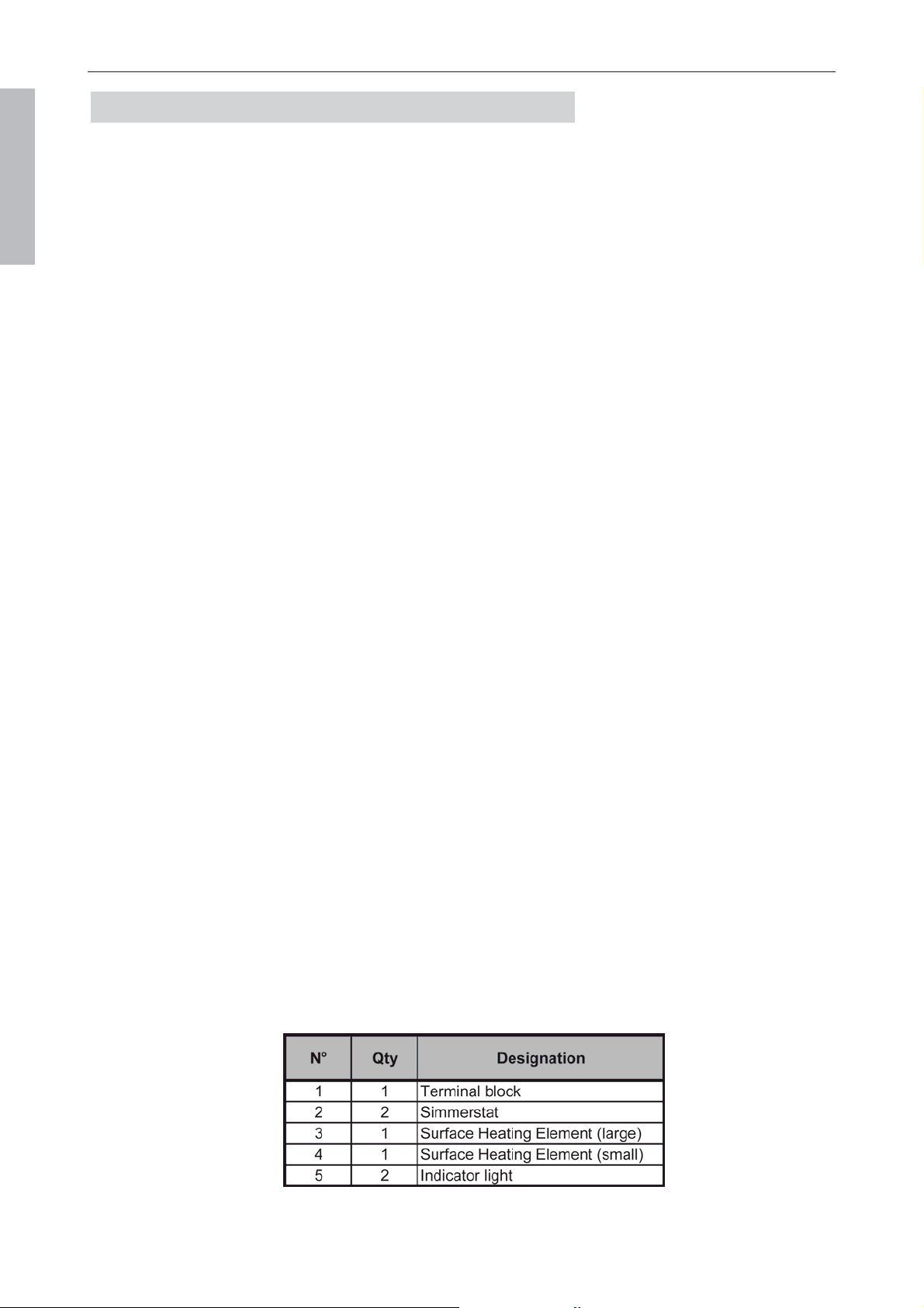
Page 52
LA CORNUE
Installation Guide Centenaire
08NOTINSTAL100/USA-8
USA & CANADA
Electrical diagrams MAINTENANCE
2. ELECTRIC COOKTOP SECTION (WHEN PROVIDED)
”CAUTION - Label all wires prior to disconnection when servicing controls. Wiring
errors can cause improper and dangerous operation.”
”Verify proper operation after servicing.”

Page 53
LA CORNUE
Installation Guide Centenaire
08NOTINSTAL100/USA-8
USA & CANADA
MAINTENANCE Electrical diagrams
3. GAS OVEN WIRING - ELECTRONIC IGNITION
”CAUTION - Label all wires prior to disconnection when servicing controls. Wiring
errors can cause improper and dangerous operation.”
”Verify proper operation after servicing.”
Gas inlet
Burner
Pressure
regulator
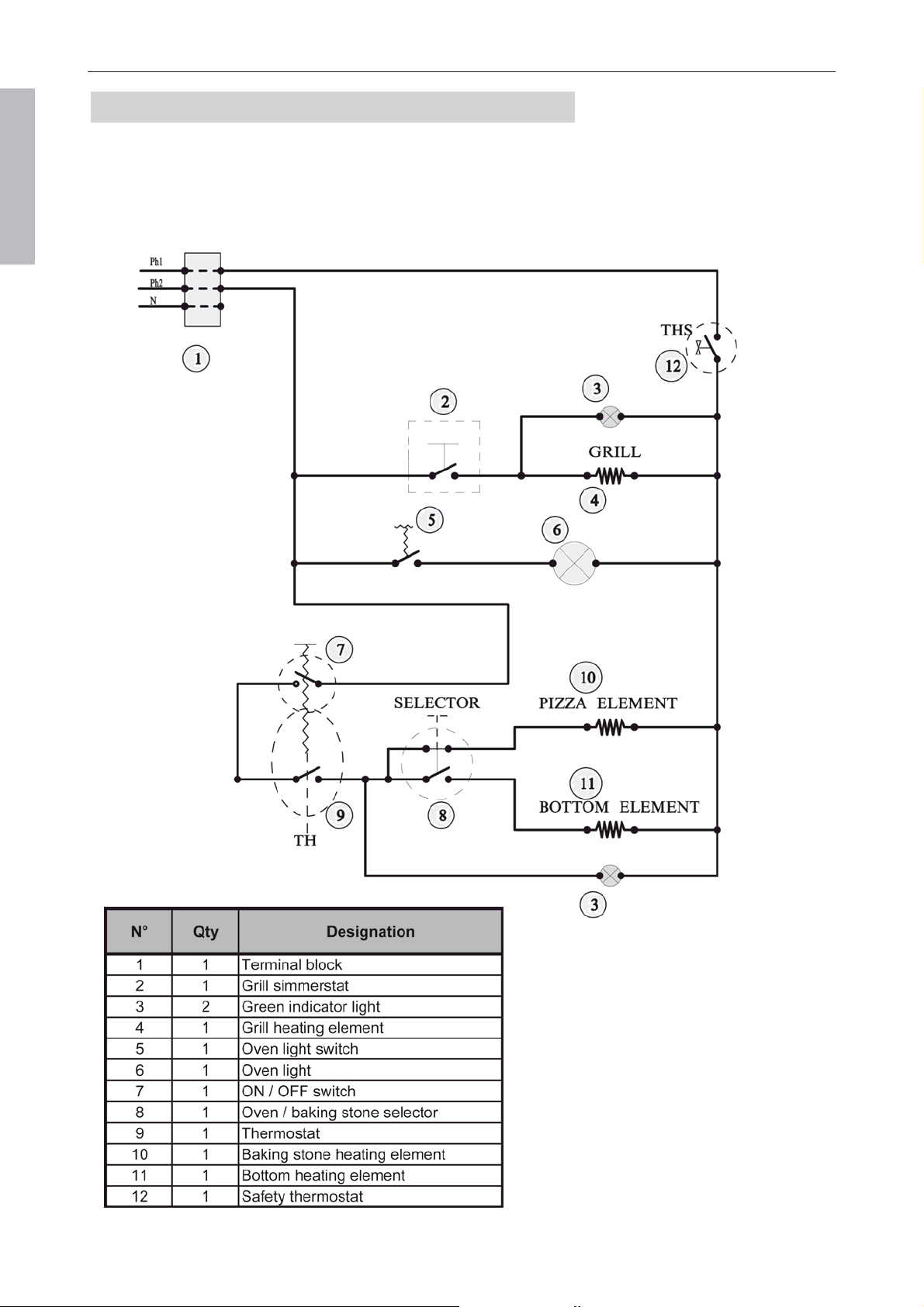
Page 54
LA CORNUE
Installation Guide Centenaire
08NOTINSTAL100/USA-8
USA & CANADA
Electrical diagrams MAINTENANCE
4. ELECTRIC OVEN
”CAUTION - Label all wires prior to disconnection when servicing controls. Wiring
errors can cause improper and dangerous operation.”
”Verify proper operation after servicing.”
Page 55
LA CORNUE
Installation Guide Centenaire
08NOTINSTAL100/USA-8
USA & CANADA
WARRANTY Warranty
W
W
A
A
R
R
R
R
A
A
N
N
T
T
Y
Y
(
(
3
3
Y
Y
E
E
A
A
R
R
S
S
)
)
La Cornue company warrants to the original user for a
period of three years from date of delivery not to
exceed 42 months from date of shipment by Company
that the product(s) manufactured by Company are
free from defects in material and workmanship.
Company shall have no obligation for any product
which has been misapplied, mishandled, abused,
misused or subjected to harsh chemical action, or
improperly installed nor to any product modified by
unqualified service personnel or damaged by flood,
fire or other acts of God or which has the serial
number removed or altered. Adjustments such as
calibrations, leveling, tightening of fasteners or utility
connections normaly associated with original
installation are the responsibility of the dealer or
installer and not that of Company.
Warranty does not cover freight charges for new or
defective parts.
The liability of Company for breach of such warranty is
exclusively limited to, at Company option, the
replacement or repair of any part found by Company
to be not as Warranted herein and, in such event
replacement or repair shall be made within 36 months
from the date of installation. The Company shall bear
the normal labor charges in effecting such
replacement or repair, to the extent that performance
is effected, within 50 miles from an office of a qualified
service agency of Company except that such
obligation to bear labor charges shall not apply to
products or parts installed outside the United States
and Canada. Replacement part(s) must be supplied
by La Cornue direct or through its dealer or qualified
service agency and the defective part(s) returned to
same intact.
This states the exclusive remedy against Company
relating to the product(s), whether in contract or in tort
or under any other legal theory, and whether arising
out of warranties, representations, instructions,
installation or defects from any cause.
Company shall not be liable, whether in contract or in
tort or under any other legal theory, for loss of use,
revenue or profit, or for substitute use or performance,
or incidental, indirect, or special or consequential
damages, or for any other loss or cost of similar type.
This warranty and the liability set forth herein are
exclusive and in lieu of all other liabilities and
warranties, express or implied, including but not
limited to implied warranties of merchantability and
fitness for particular purpose and constitutes the only
warranty of Company with the respect to product(s).
IMPORTANT INFORMATION:
When requesting information, manuals, replacement parts or service, always refer to the model
and serial number of your unit. The serial plate is located behind or on the lower drawer.
For your convenience space is provided below to record this information for future reference.
SERIAL No
M
ODEL No
D
EALER
INSTALLATION DATE
Page 56
LA CORNUE
Installation Guide Centenaire
08NOTINSTAL100/USA-8
USA & CANADA
Address LA CORNUE
FRANCE
Ateliers La Cornue
14, rue du Bois du Pont - Z.I. les Béthunes
95310 Saint-Ouen l'Aumône - FRANCE
Phone: + 33 (0)1 34 48 36 36 - Fax: + 33 (0)1 34 64 32 65
Postal address:
La Cornue SAS - B.P. 99006
95070 Cergy Pontoise Cedex - FRANCE
www.lacornue.com
e-mail: [email protected]
USA
185 Park Lane, Brisbane, CA 94005 - USA
Phone: 800-457-1356 or 415-468-6620, Fax: 415-358-4377
After-sales Service:
of 7:00 a.m. and 4:00 p.m. Pacific Time,
Monday through Friday, excluding national Holidays
by calling 877-LACORNUE
CANADA
SOFA Galleries, 6900 Airport Road,
Suite 205, Mississauga, ONT L4V 1E8, Canada
T.: 855-213-2785 F.: 905-678-4854
You can find these instructions on following web sites:
USA
www.lacornueusa.com
Canada
www.lacornue.com/ca

Ateliers La Cornue
14, rue du Bois du Pont - Z.I. les Béthunes - 95310 Saint-Ouen-l’Aumône
FRANCE
Postal address / Adresse postale:
La Cornue SAS - B.P. 99006 - 95070 Cergy-Pontoise Cedex - FRANCE
Phone / Tél.: +33 (0)1 34 48 36 36 – Fax: +33 (0)1 34 64 32 65
E-mail: a.table@la-cornue.com
www.lacornue.com

