Before attempting to install the tankless electric water heater, please take the time to read and understand the installation
and safety manual thoroughly and carefully. The manual contains important safety tips and instructions.
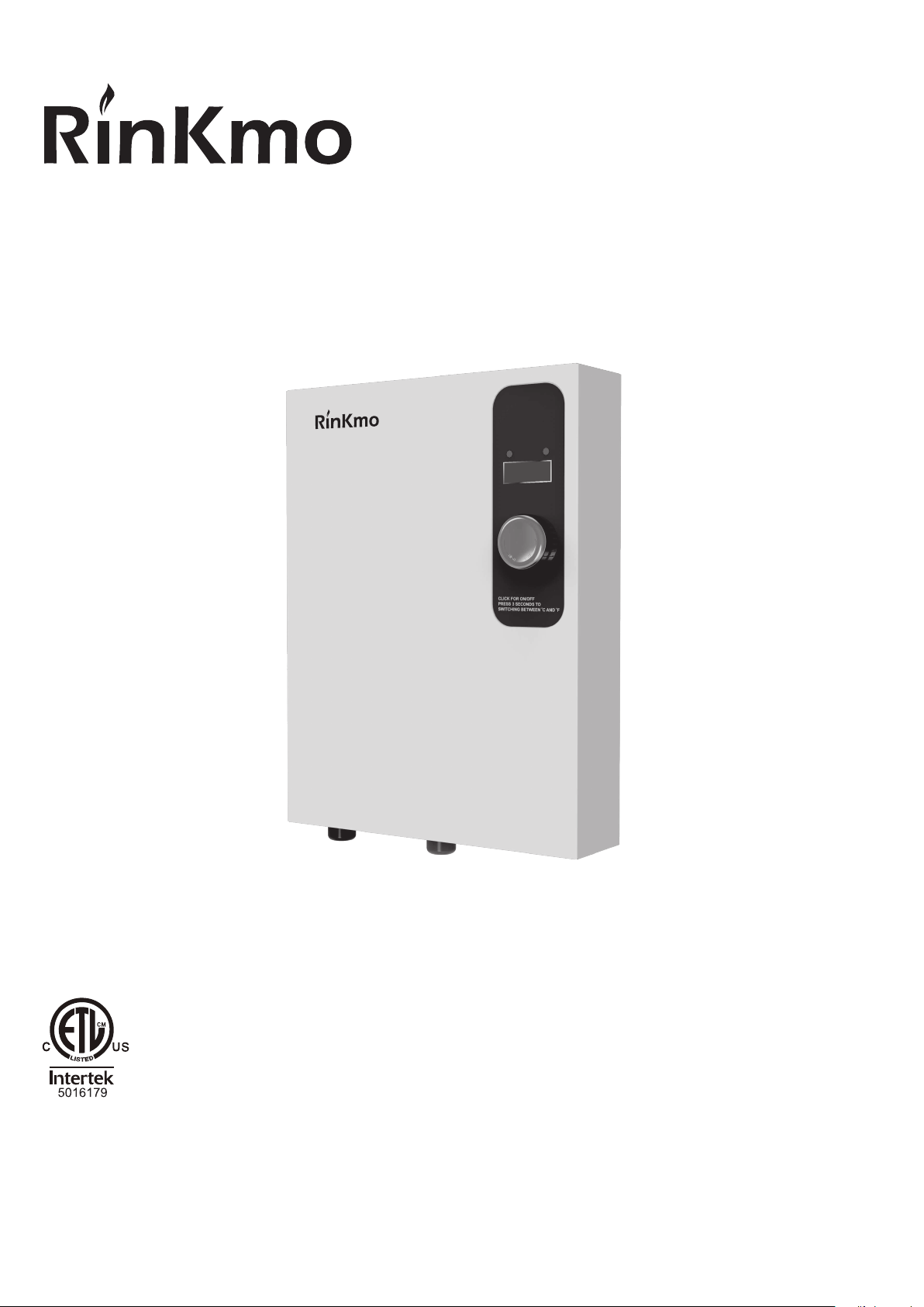
INSTALLATION AND USER INSTRUCTIONS
TANKLESS ELECTRIC WATER HEATERS
READ AND SAVE THESE INSTRUCTIONS
Installer: Leave this manual with the homeowner.
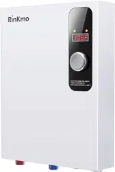
EI18
EI24
Model:
8888
WARNING
▲ This water heater is used to provide domestic hot water
for household use and can provide multiple outputs.
▲ If the water heater is not used, the connection with
power supply shall be cut off. In order to avoid a hazard.
▲ If it is not used for a long time in winter, Drain the water
from the the water heater to avoid water frozen which will
damage the container. Please cut off the power supply
before emptying.
▲ Keep the instructions after installation, you may need it
later to get more information and support.
NOTE: This unit has multiple power inputs. Shut off all
breakers before maintenance.
IMPORTANT INFORMATION
Thanks for being a valued Customer.
Hope this electric water heater you purchased could make
your life better as we expected.
You're covered with Rinkmo 1-year free warranty to
against any manufacturing defect. You are always
welcome to reach us for warranty service or technical
support, especially
1) when you received a damaged, defective electric water
heater;
2) when you have any concerns, questions, or problems
while using this electric water heater.
We will always appreciate your emails, and just as we are
glad that you let us know something had gone wrong.
To access customer service for technical support or
warranty service, please email to rinkmo.service@out-
look.com.
▲ To ensure your own safety and that of others you need
to read the installation and user instruction carefully before
using the unit for the first time; Failure to comply with the
instruction may cause property damage, serious injury, or
death; If you have any questions, contact our company or
the maintenance personnel appointed by our company.
▲ This unit should be installed by a qualified electrician or
plumber in accordance with federal, state and local
electrical and plumbing codes.
▲ When installing or using any high voltage electrical
appliance, basic safety precautions should always be
followed.
▲ DO NOT install this unit in a location where it may be
subject to freezing temperatures. If the water inside your
tankless water heater freezes, it can cause severe and
permanent damage that is not covered under your warranty.
▲ Water temperature over 125°F (52°C) can cause severe
scalding. If the set temperature of the unit is too high, there
is the possibility of hot water scalding. Children, disabled
persons or the elderly in small households may need to set
the temperature of the product below 113°F (45°C) in order
to prevent possible harm caused by hot water.
▲ Where children or persons with limited physical, senso-
ry or mental capabilities are to be allowed to control this
appliance, ensure that this will only happen under supervi-
sion or after appropriate instructions by a person responsi-
ble for their safety. Children should be supervised to
ensure that they never play with the appliance.
▲ This unit has more than one power-supply connection
point. Disconnect all power supplies before servicing.
▲ To avoid damage, the unit needs to be kept dry. Keep
unit away from direct sunlight, moisture, dust, steam, and
other liquids.
The unit do not installed in places with water leaks (such
as under air conditioning lines that might leak or condense
moisture or water pipes ).
▲ Be sure that the water heater are out of the reach of
children so they cannot adjust the temperature knob at will.
▲ The outlet water pipe can get very hot, make sure that
the outlet water pipe is out of the reach of children, and
must be insulated.
▲ This product is only used to heat water, do not use it to
heat other liquids.
▲ Damage caused by water quality is not covered by the
warranty.
▲ Make sure all circuit breakers and disconnect switches
are off before installation and maintenance.
▲ Do not store inflammables and explosives near the
water heater.
▲ Piping that has been treated with boiler seal, chromates,
or other chemicals is not allow to use.
Attentions: This water heater must be connected to a
reliable earth connection at all times.
INSTALLATION INSTRUCTIONS
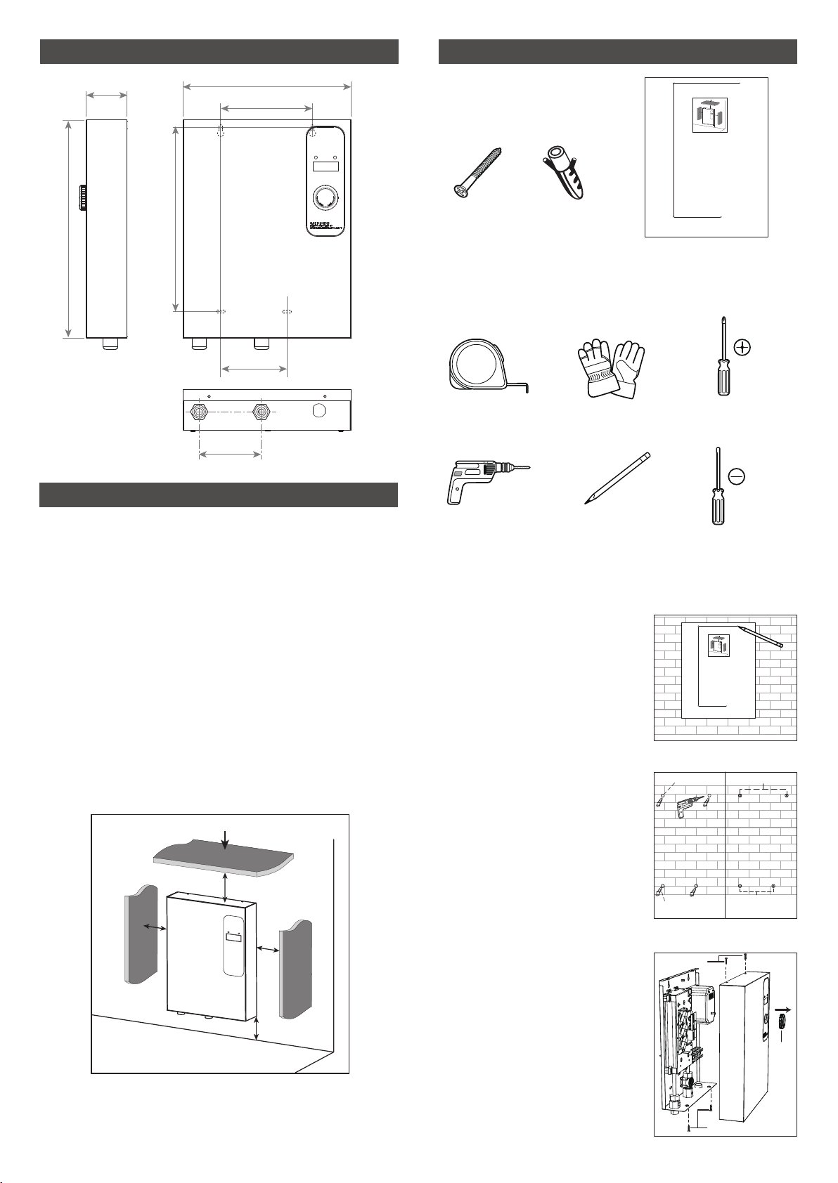
1. Mark the positions of mounting
holes on the wall as the installation
template shows (Fig. 1).
NOTE: For ease of installation
and servicing, we recommend
that this unit be installed in an up
right position with the inlet and
outlet water connections at the
bottom.
2. Drill 4 mounting holes
(Ø6x32mm) at the marked position
(Fig. 2).
3. Put espansion boltes into the
holes (Fig. 2).
4. Put two screws into the upper two
holes (Fig. 3).
5. Remove the knob on front cover
and 4 screws on the top and
bottom edges of the unit, and then
dismantle the front cover (Fig.4).
BEFORE MOUNTING
* THE UNIT MUST BE INSTALL BY QUALIFIED ELEC-
TRIC ENGINEER
1. The wall for installation of water heater must be firm and
solid and can bear four times the weight of the water
heater.
2. Indoor installation only. Do not install this water heater
near flammable, volatile substances or strong magnetic
fields. The unit must be installed in the vertical position of
the water pipe joint.
3. Be sure that the external power harness and air-opening
meet the standard requirements.
4. Gloves are required during installation.
PRODUCT DIMENSIONS
MOUNTING YOUR WATER HEATER
MOUNTING YOUR WATER HEATER
4 7/8"
(124mm)
7 1/8" (180mm)
3 1/8"
(80mm)
5 1/8"
(130mm)
13 1/8" (334mm)
14 1/4" (363mm)
14 1/4" (363mm)
Fig. 4
Fig. 1
Fig. 2 Fig. 3
Knob
Screw
Screw
Accessories contents
TOOLS/MATERIALS REQUIRED
(not include)
Measuring tape
Pencil
Phillips
screwdriver
Slotted
screwdriver
Safety gloves
Electric drill
1 installation template4 espansion
boltes
4 screw
st 4.2x30
mounting
hole
espansion
bolte
Screw
espansion
bolte
c
b
a
a
Wall or other fixed objects that cannot be moved
INSTALLATION LOCATION
There should be a certain space around the machine for
installation and future maintenance.
a (side gap): minimum 12" (305mm)
b (top gap): minimum 15" (381mm)
WALL
7 1/8" (180mm)
5 1/8" (130mm)
14 1/4" (363mm)
WARNING: This unit should be installed by a qualified electrician or plumber in
accordance with federal, state and local electrical and plumbing codes.
WARNING: This water heater must be connected to a reliable earth connection
at all times.
WARNING: Make sure all circuit breakers and disconnect switches are off before
installation and maintenance.
WARNING: DO NOT install this unit in a location where it may be subject to
freezing temperatures. If the water inside your tankless water heater freezes, it can
cause severe and permanent damage that is not covered under your warranty.
The wall for installation of water heater must be firm and solid and can bear four
times the weight of the water heater.
WARNING: Indoor installation only. Do not install this water heater near
flammable, volatile substances or strong magnetic fields. The unit must be
installed in the vertical position of the water pipe joint.
This unit has more than one power-supply connection point. Disconnect all
power supplies before servicing.
WARNING: To avoid damage, the unit needs to be kept dry. Keep unit away from
direct sunlight moisture, dust, steam, and other liquids.
WARNING: The unit do not installed in places with water leaks (such as under
air conditioning lines that might leak or condense moisture or water pipes ).
WARNING: Be sure that the water heater are out of the reach of children so they
cannot adjust the temperature knob at will.
WARNING: The outlet water pipe can get very hot, make sure that the outlet
water pipe is out of the reach of children.
Installation location
There should be a certain space around the machine for
installation and future maintenance.
c
b
a
a
Wall or other fixed objects that cannot be moved
a (side gap): minimum 12" (305mm)
b (top gap): minimum 15" (381mm)
WALL
SUGGESTION:
WARNING: c (bottom gap): keep a distance out of the
reach of children
7 1/8" (180mm)
5 1/8" (130mm)
14 1/4" (363mm)
WARNING: This unit should be installed by a qualified electrician or plumber in
accordance with federal, state and local electrical and plumbing codes.
WARNING: This water heater must be connected to a reliable earth connection
at all times.
WARNING: Make sure all circuit breakers and disconnect switches are off before
installation and maintenance.
WARNING: DO NOT install this unit in a location where it may be subject to
freezing temperatures. If the water inside your tankless water heater freezes, it can
cause severe and permanent damage that is not covered under your warranty.
The wall for installation of water heater must be firm and solid and can bear four
times the weight of the water heater.
WARNING: Indoor installation only. Do not install this water heater near
flammable, volatile substances or strong magnetic fields. The unit must be
installed in the vertical position of the water pipe joint.
This unit has more than one power-supply connection point. Disconnect all
power supplies before servicing.
WARNING: To avoid damage, the unit needs to be kept dry. Keep unit away from
direct sunlight moisture, dust, steam, and other liquids.
WARNING: The unit do not installed in places with water leaks (such as under
air conditioning lines that might leak or condense moisture or water pipes ).
WARNING: Be sure that the water heater are out of the reach of children so they
cannot adjust the temperature knob at will.
WARNING: The outlet water pipe can get very hot, make sure that the outlet
water pipe is out of the reach of children.
b
b
a
a
Wall or other fixed objects that cannot be moved
a (side gap): minimum 12" (305mm)
b (bottom gap): minimum 15" (381mm)
WALL
Installation location
There should be a certain space around the machine for
installation and future maintenance
SUGGESTION:
WARNING: c (bottom gap): keep a distance out of the
reach of children
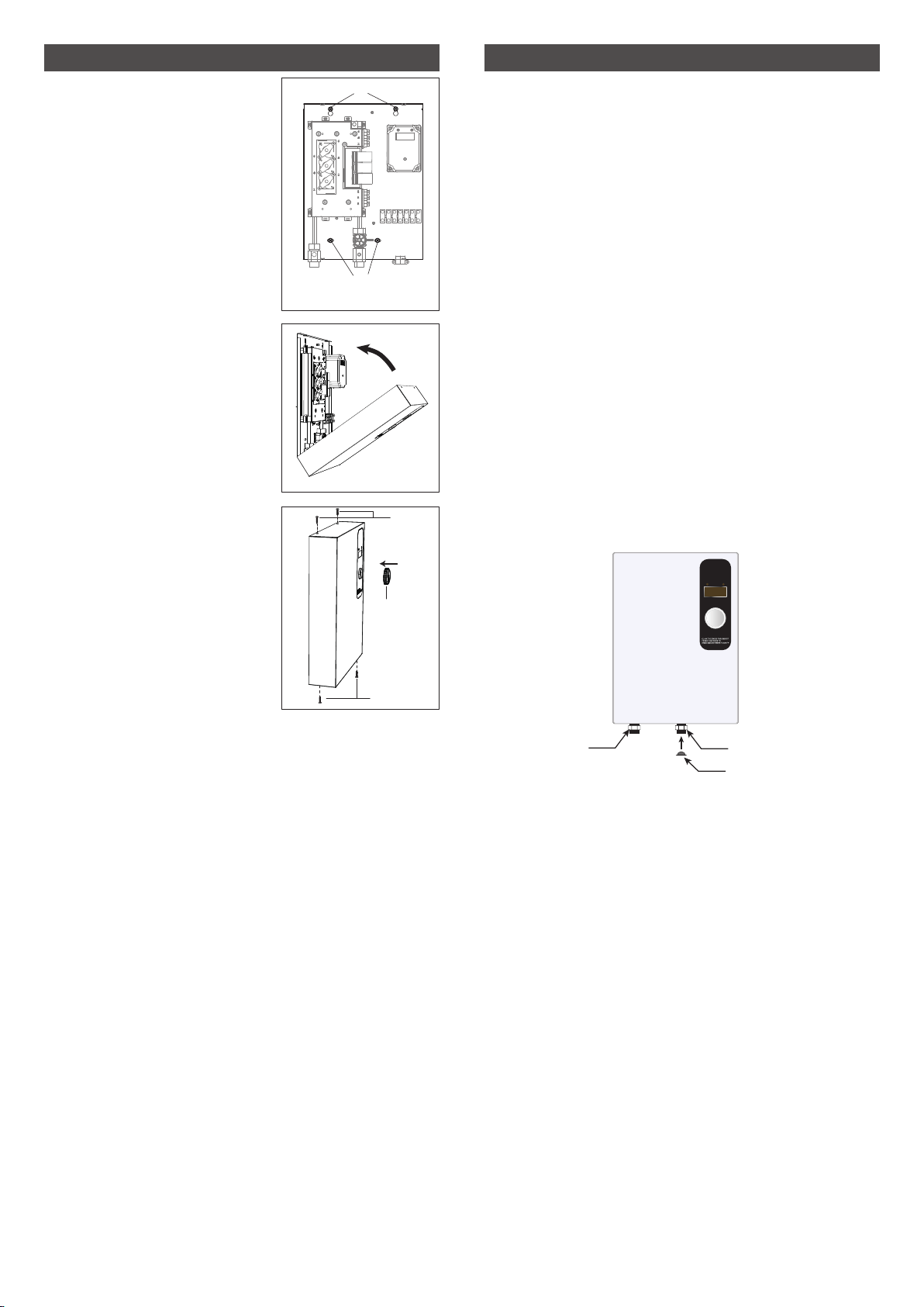
6. Hang the body on the two
installed screws, then fix the
other two screws.
Tighten all 4 screws to secure the
body.
NOTE: Make sure that the
mounting surface is solid and
firm, and ensure that the unit is
level prior before tighten the
screws (Fig. 5).
7. Reinstall the front cover after
finish “PLUMBING INSTALLA-
TION” and “ELECTRICAL
INSTALLATION”.
Fasten the front cover only after
confirming that the mounting
screws are firm and reliable.
The front cover mounting shows
as right (Fig. 6).
WARNING: The electrical compo-
nents inside the water heater
may cause serious personal
injury or electric shock death.
Make sure that the front cover is
installed correctly and firmly. Do
not remove the front cover unless
installation or maintenance.
8. Screw the front cover to body.
Reinstall the knob (Fig. 7).
PLUMBING INSTALLATION
MOUNTING YOUR WATER HEATER
CAUTION: The plumbing installation must be completed
before the electrical installation.
WARNING: It is the responsibility of the Service Person to
ensure that the water supply to the equipment is provided
with protection against backflow by an air gap as defined
in ANSI/ASME A112. 1.2-1979; or an approved vacuum
breaker or other such method as proved effective by test.
WARNING: Pipe dope or PVC/CPVC primer and glue is
not allowed to used on the threads of the outlet and inlet
fittings. These chemicals can damage the nipples and
cause leaks. Only thread sealing tape can be used.
SUGGESTION: To avoid the property damage caused by
leakage (small probability event), the machine needs to be
installed in place with floor drain.
SUGGESTION: Install a valve (not include) at the inlet
pipe for future maintenance.
SUGGESTION: Install a pressure relief valve between
valve and unit if the inlet water supply pressure exceeds
150 PSI.
Installation Instructions
1. Facing the unit, the outlet located marked on the left
side of the unit connect to the hot water line. The inlet
located marked on the right side of the unit connect to the
cold water line.
8888
Fig. 5
Fig. 6
Fig. 7
Knob
Screw
Screw
2. After tightening both fittings at the unit, open the hot
water tap to allowed water run through the unit for about 2
to 3 minutes, to make sure all the air is discharged from the
water lines. This step must be performed before power on.
IF DO NOT FOLLOW THIS STEP CAN CAUSE PERMA-
NENT DAMAGE TO THE HEATING ELEMENTS.
3. Close outlet, open inlet, to check all connections for
water leaks.
Outlet pipe
Inlet pipe
Filter*
Screw
Screw
* This part is in the Inlet pipe
ELECTRICAL INSTALLATION
ELECTRICAL INSTALLATION
Before installing the water heater, make sure that your
home has enough power to handle the maximum current
available for this product.
As with all high-power electrical products, Make sure to
turn off all power to the product directly at the fuse or
breaker box before installing, repairing or disassembling
this water heater.
All circuit protection (breakers) and wiring (wire gauge)
must conform to the US National Electrical Code (NEC) in
the America or Canadian Electrical Code (CEC) in the
Canada .
Failure to comply with these warnings can lead to the
risks include fire, electrical shock and/or death and
void your warranty.
Before starting the electrical installation work, make sure
that all water pipelines have been installed and the main
circuit breaker and power switch have been closed to
prevent electric shock.
CAUTION: Ensure that you have made the correct
connections. You must follow the wire connection as
shown in ensure proper operation of the unit.
WARNING: For supply connections use 8 AWG or larger
wires suitable for at least 160°F (75°C).
WARNING: This product has more than one power-supply
connection point. Disconnect all power supplies before
servicing.
WARNING: The overcurrent protective devices are
provided as a separate assembly, the product shall be
used only with this separate assembly.
WARNING: Firstly turn on the water and let it to run in the
product for several minutes, and exhaust all the air in the
plumbing. At the same time, check whether there is water
leakage at the internal and external water connections of
the product.
WARNING: To avoid a short circuit and damage the circuit
board, make sure all strands are secure inside the terminal
block.
L2
connector
L1
L2
L1
L2
L1
R1
R3
G
R2
heating
element
heating
element
heating
element
PCB 3
PCB 3
PCB 3
PCB 1
thermal cut-out
thermal cut-out
thermal cut-out
t0
t1
flow sensor
temperature
sensor
PCB 2
triac
triac
triac
EI18
EI24
L2
connector
L1
L2
L1
heating
element
heating
element
R1
G
R2
PCB 3
PCB 3
PCB 1
thermal cut-out
thermal cut-out
t0
t1
flow
sensor
temperature
sensor
PCB 2
triac
triac
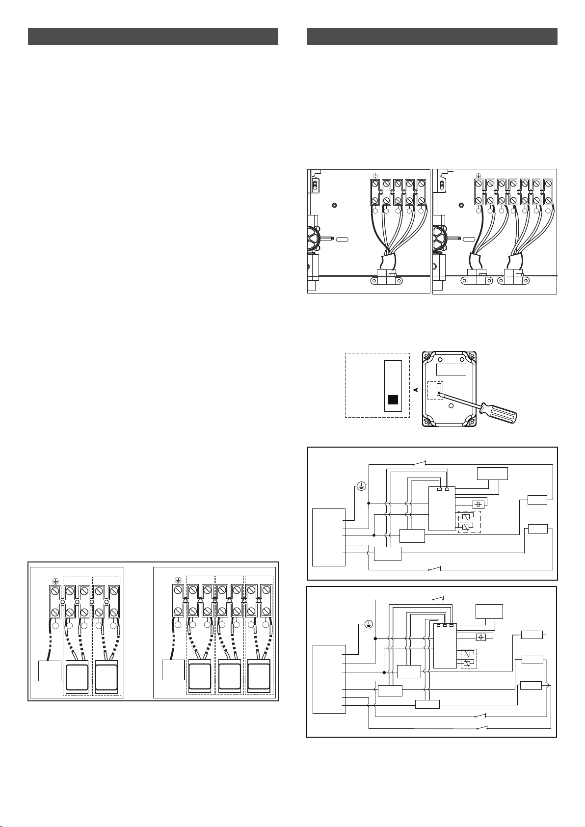
NOTE: The rated voltage is 240VAC. If the connected
power supply is 208VAC, please turn the dial switch
on the display PCB to the upper side with a slotted
screwdriver
Circuit Diagram
Wiring diagram
208VAC
240VAC
8888
208VAC
240VAC
G
L2 L1
L2 L1 L2 L1
123456
G
L2 L1 L2 L1
1234
EI18
EI24
Circuit Connection
1. Connect each group of power wires to a circuit breaker
in pairs (show as below). Make sure that each circuit
breaker is connected one group of L1 and L2.
EI18 need two circuit breakers.
EI24 need three circuit breakers.
2. When connecting the power cords to the terminal block,
make sure that the wire and the electric conductor inside
the terminal block are in full contact. Then tighten the
screws. If it is loose, May causing electrical short circuit
and/or the terminal block burn out.
Circuit
breaker
Circuit
breaker
Circuit
breaker
G
L2 L1
L2 L1 L2 L1
123456
Ground
Circuit
breaker
Circuit
breaker
Ground
G
L2 L1 L2 L1
1234
EI18 EI24
3. Again make sure that the wiring from the main circuit
breaker to the water heater is correct. If the wrong wires is
connected, the product will not work normally and may
cause unnecessary danger.
4. Check earth resistance and make sure there is a proper
earth continuity.
5. Confirm that all the air has been purged from the water
lines prior to turning on power to the unit.
8888
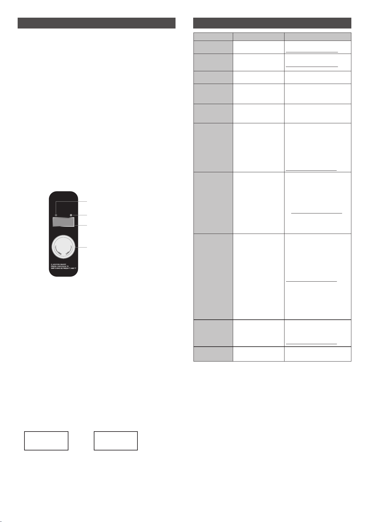
OPERATION INSTRUCTIONS
TROUBLESHOOTING
Power indicator
Heating indicator
Temperature display
Knob
Power On
When the mains power supply is switched on, the buzzer
beeps once and all the indicators light up for three
seconds and then go out except power indicator. Power
indicator is on green, heating indicator and display screen
are not on.
Operation
1. Press the knob (a beep can be heard) to turn on the
water heater power, the LED display will turn on, it shows
the actual outlet water temperature. Heating indicator is on
red in the state of heating.
Note: The unit will not work and the heating indicator is not
on if there is no water flow, or the water flow do not meets
the start-up requirements (0.66GPM/2.5L/min).
2. If the unit is frequently used and the intermediate
interval is short, initially a short burst of very hot water from
the unit will flow out, wait a few seconds for the water to
cool down to the set temperature when using.
CAUTION: Regularly clean the inlet filter and the shower
head to get enough flow.
PROBLEM ISSUE POSSIBLE CAUSE SOLUTION
Display E1 / E0
Display E2 / E3
Display LL
Inlet temperature
sensor failure.
Inlet temperature lower
than 37°F (3℃)
Unit do not work when inlet
temperature lower than 37°F (3℃).
Display HH
Inlet temperature higher
than 176°F (80℃)
Unit do not work when inlet
temperature higher than 176°F
(80℃).
Contact:
Contact:
1. Make sure that the main circuit
breakers that supply the water heater
is on.
2. The unit may be wired error.
3. There may is a problem with the
circuit breaker.
4. Contact:
Outlet temperature
sensor failure.
1. Turn up the setting temperature.
2. Reduce water flow.
3. If the first installation occurs,
please let the electrician check the
wiring carefully. The wiring may be
incorrect.
If not contact:
4. Check the power supply.
5. Replace temperature sensor.
6. Replace heating element.
Water leakage at the
inlet and outlet
connector.
1. The connector is
not installed in place.
2. Seal damage.
1. Tighten the connector.
2. Replace the seal.
The unit does not
work (Power
indicator is NOT on)
Incorrect power wiring
connection or no power.
Water heater is not
heating at all (Power
indicator is on)
Water heater is
working but the outlet
temperature is not
hot well.
1. Low Setting temperature
2. Excessive water flow
3. Faulty wiring
4. Voltage too low.
5. Temperature sensor
failure.
6. Heating element
damaged.
1. Turn down the setting temperature
2. Increase water flow
3. Cut off the power and contact:
Water heater is
heating but the outlet
temperature is too
hot.
1. Temperature set too high.
2. Low water flow
3. PCB failure
Clean themThe outlet flow is
reduced.
Inlet filter,shower or faucet
clogged.
1. No water flow.
2. The flow too small to start
up the unit.
3. Control board failure.
1a. Check the water supply channel;
1b. Clean filter at unit;
1c. Clean faucet aerator or shower
head.
2. Increase water flow.
3. Cut off the power and contact:
Temperature Control
In the state of heating the outlet water temperature can be
adjusted by turning the knob. Turn the knob clockwise to
increase the outlet temperature, and turn the knob coun-
terclockwise to decrease the outlet temperature between
80°F – 140°F (26℃- 60℃), the factory set temperature is
95°F.
When the setting temperature is turned to the maximum or
minimum, it will be not changed and two beeps will be
heard at the same time.
Fahrenheit / Celsius Switch
●The factory set temperature of the unit is Fahrenheit.
● In the state of heating, press the knob for 3 seconds, the
display will switch between Fahrenheit and Celsius.
● When fahrenheit is displayed, the last text shows F.
● When celsius is displayed, the last text shows C.
35C
95f
Fahrenheit display Celsius display
NOTE: When the outlet water temperature reaches 167°F
(75℃) the unit will stop heating.
TECHNICAL SPECIFICATION
Phase Single 60 Hz
Amperage draw
Min. wire size
(copper)
Min. Water Flow
Water connection
Watts
Temp
Rise
EI18Model
@1.5GPM
@2.25GPM
@3.0GPM
3/4"NPT
208V 240V
208V 240V
2x38A2x33A
18.0kW13.5kW
80℉
54℉
40℉
60℉
40℉
30℉
0.66GPM/2.5L/min
Working pressure
150PSI/10BAR
2x8AWG
EI24
3x34A
24.0kW
92℉
73℉
54℉
3x29A
18.0kW
80℉
53℉
40℉
3x8AWG
Voltage