Model No. 831.159730
Serial No.
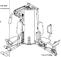
The serial number is found in the
location shown below. Write the
serial number in the space above.
Serial
Number
Decal
EXERCISE
EQUIPMENT
H __LP LI N E_ !
1-800-72,6-6879
SEARS, ROEBUCK AND CO.
HOFFMAN ESTATES, IL 60179
CAUTION
Read all precautions and instruc-
tions in this manual before using
this equipment. Save this manu-
al for future reference.
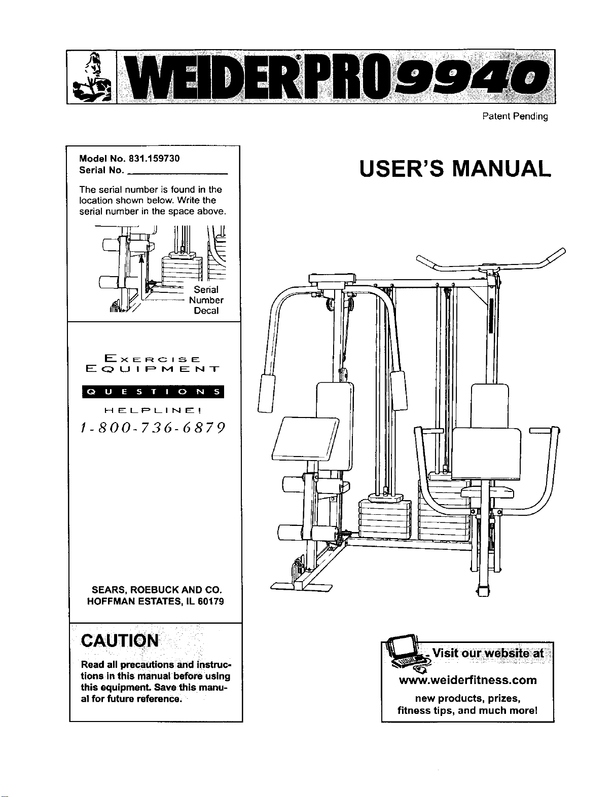
Patent Pending
USER'S MANUAL
www.weiderfitness.com
new products, prizes,
fitness tips, and much morel
ImportantPrecauttons
Before You Begm
Assembly
Cable Diagrams
Adjustment
Trouble-shooting and Mamtenance
Weight Resistance Chart
Ordering Replacement Parts
Full 9g-day Warranty
2
3
.4
23
25
26
27
Back Cover
Back Cover
Note. A PART LIST/EXPLODED DRAWING and a PART IDENTIFICATION CHART are attached in the center of
th_s manual Remove the PART LIST/EXPLODED DRAWING and the PART IDENTIFICATION CHART before
beginning assembly.
^*1 WARNING: To reduce the risk of serious injury, read the following Important precau-
tions before using the home gym.
1. It is the responsibility of the owner to ensure
that all users of the home gym are adequate-
ly informed of all precautions.
7. Always stand on a foot plate when perform-
ing an exercise that could cause the home
gym to tip.
2. Read all instructions in this manual and in
the accompanying literature before using the
home gym.
3. If you feel pain or dizziness at any time while
exercising, stop immediately and begin cool-
ing down.
8. Keep hands and feet away from moving parts.
9. Keep children under the age of t2 and pets
away from the home gym at all times.
t0. Always wear athletic shoes for foot protec-
tion when exercising.
4. Use the home gym only on a level surface.
Cover the floor or carpet beneath the home
gym for protection.
11. Never release the press arms, butterfly arms,
leg lever, lat bar or ab strap while weights are
raised. The weights will fall with great force.
5. Inspect and tighten all parts often. Replace
any worn parts immediately.
6. Make sure the cables remain on the pulleys
at all times. If the cables bind while you are
exercising, stop immediately and make sure
the cables are on all of the pulleys.
12. Alwavs disconnect the lat bar or ab strap
frgm the home avm when Derformina an
exercise that does not use the attachments.
13. The home gym Is intended for home use only.
Do not use the home gym in a commercial,
rental or institutional setting.
WARNING: Before beginning this or any exercise program, consult your physician. This is especially
important for persons over the age of 35 or persons with pre-existing health problems. Read all
instructions before using. SEARS assumes no responsibility for personal injury or property damage
sustained by or through the use of this product.
2
Thank you for selectingthe innovativeand versatile
WELDER®PRO 9940 Home Gym. The WELDER®PRO
9940 offers a unique selectionof weightstations
designed to develop every major muscle groupofthe
body.Whether your goal is totone your body,build
dramatic muscle size and strengthor improve your
cardiovascularsystem, the WELDER®PRO 9940
makes iteasy to achieve the resultsyouwant.
For your benefit, read this manual carefully before
using the WELDER®PRO 9940 Home Gym. If you
have additionalquestions, please call ourtoll-free
HELPLINE at 1-800-736-6879, Monday through
Saturday, 7 a.m. until7 p.m. Central Time (excluding
holidays).To help usassistyou, please note the prod-
uctmodel number and serialnumber before calling.
The model number is831.159730. The serial number
can be found on a decal attached to the WELDER®
PRO 9940 Home Gym (see the front cover ofthis
manual).
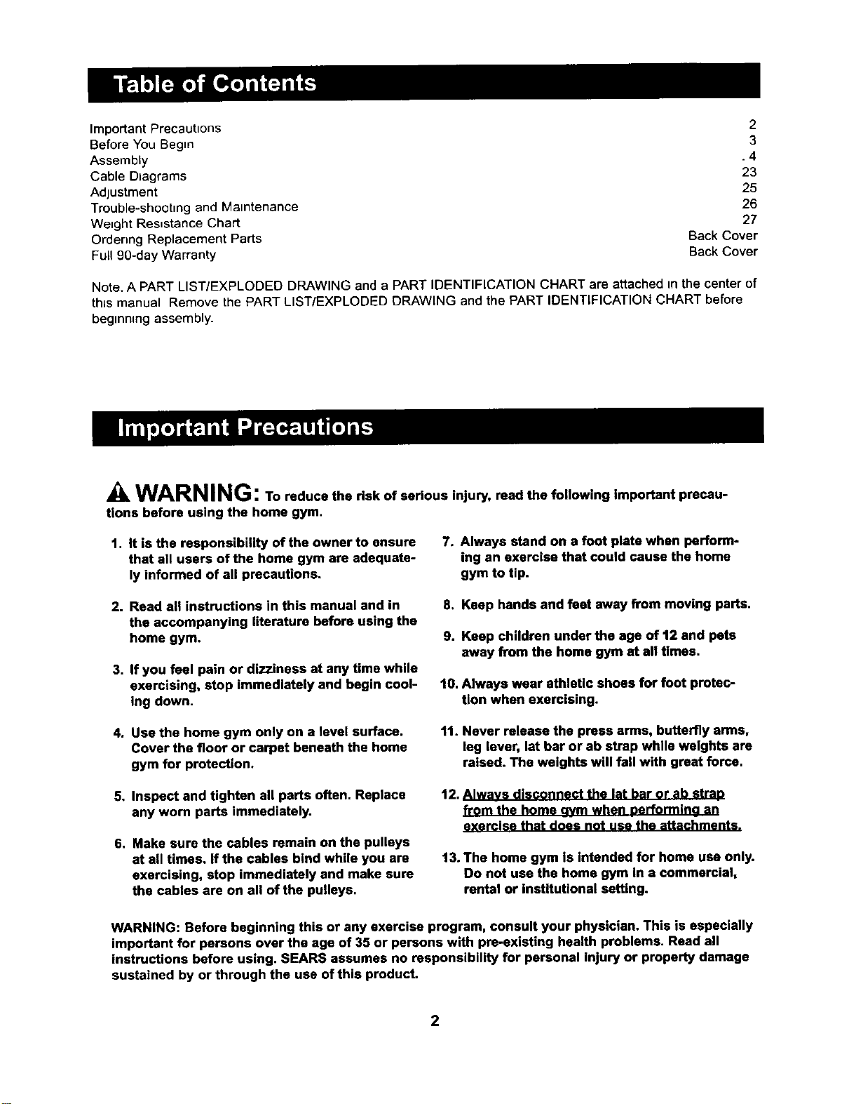
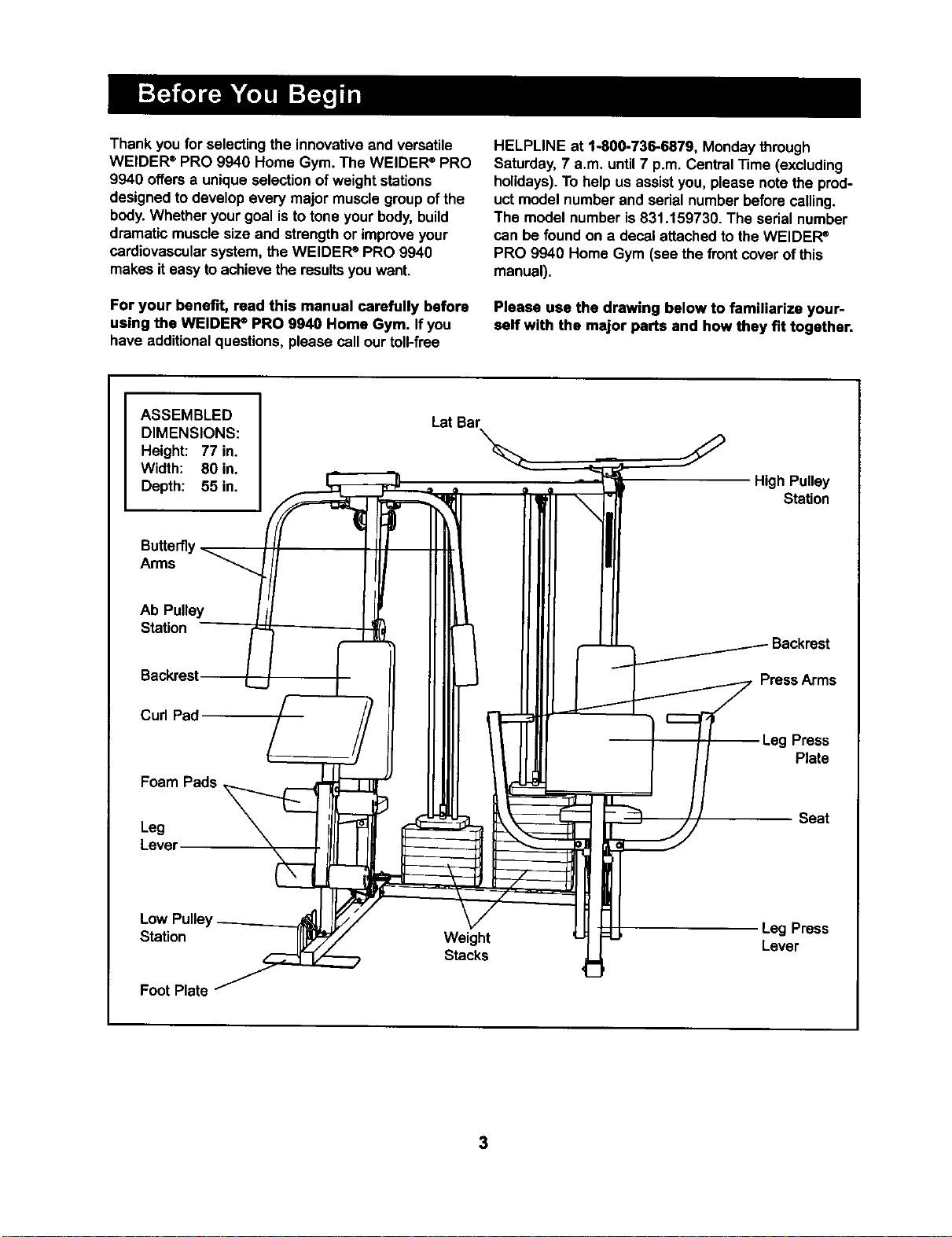
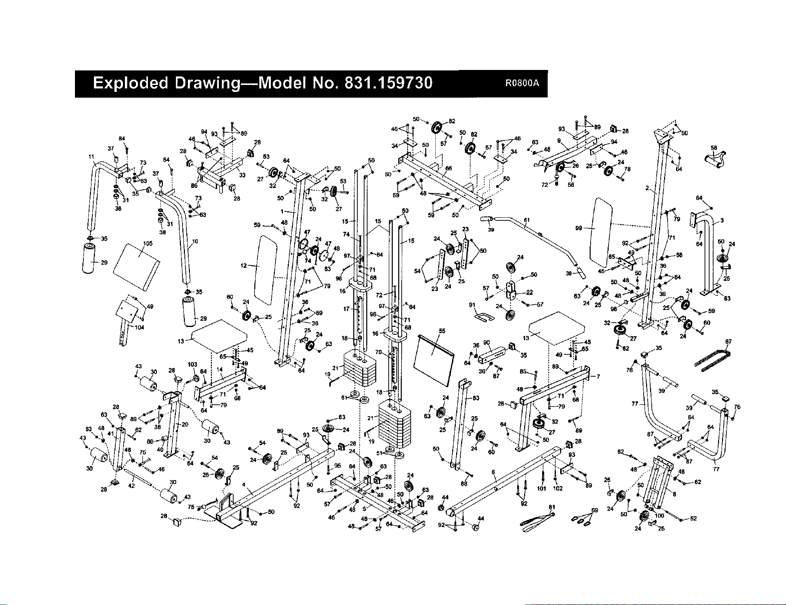
Please usa the drawing below to familiarize your-
self with the major parts and how they fit together.
ASSEMBLED
DIMENSIONS:
Height: 77 in.
Width: 80 in.
Depth: 55 in.
BuRe_y
Arms
Ab Pulley
Station
Backrest [
Curl Pad
Foam Pads
Leg
Lever
Low Pulle_
Station
Foot Plate
Lat Bar
Weight
Stacks
High Pulley
Station
PressArms
Leg Press
Plate
Seat
Leg Press
Lever
3
Note: This introduction will save you more time
than it takes to read itl
MaDdr__lngs _Ser for_yo.rs=_i
by anyone. However,;iHs_i_to_ealize' ,
tl_t your newequi._..:is a,_ prod-_
wmtake_ _ houm.!Mo=peo-
by.deddlrigtomakethe.ta_eejWal_i,usam--
bWy_1iOo:=_==li_s:Y=;Jiiiis wantio'ix_nplete.
the precessover_tooupieof eventhg_
, '_.
Some assembly steps require two people.
Giving Yourself a Good Start
Beforeyou begin the assembly processitself,take
the bmeto complete the steps outlinedhere.
Clearing the Workspace
Clear a workspace that is largeenough to holdall
parts and allow you to walk all the way around the
assembled equipment.
Unpacking the Box
To make the assembly processas smoothas possi-
ble,we have broken it intoseparate stages. Allparts
used in each stage are found in individualpackages
in the shippingbox. Place all parts in a cleared area
and removethe packing materials. Do not disposeof
the packingmaterials untilassembly _scompleted.
Important: Wait until you begin each assembly
stage to open the parts bag labeled for that
assembly stage,
Identifying Parts
To helpyou identifythe small parts used in assem-
bly,we have includeda PART IDENTIFICATION
CHART located in the center ofth_smanual. Place
the chart on the floor or worktable and use itto
quickly identifydifferentpartsas you open the pack-
ages for each step. Note Some small parts may
have been pra-attached for shipping.If a partis not
in the parts bag, check to see if ithas been pre-
attached.
Orienting Parts
As you assemble this product,be sure that all parts
are orientedas shown in the drawings.
Tightening Parts
Tighten all partsas you assemble them, unless
instructedto do otherwise.
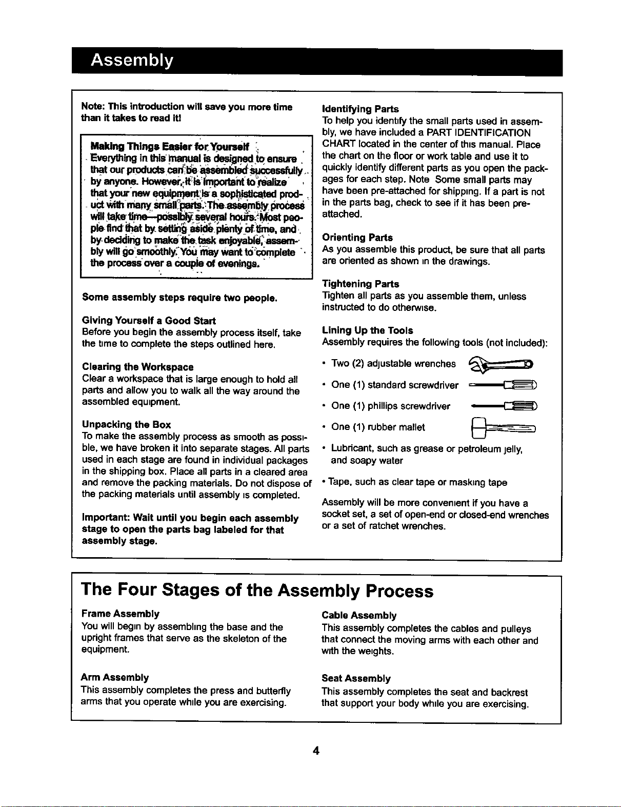
Lining Up the Tools
Assembly requiresthe following tools (not included):
• Two (2) adjustablewrenches
• One (1) standard screwdriver
• One (1) phillipsscrewdriver
• One (1) rubber mallet
• Lubricant,such as grease or petroleumjelly,
and soapy water
• Tape, such as clear tape or maskingtape
Assemblywill be more convenientif you have a
socketset, a set ofopen-endor closed-endwrenches
or a set of ratchet wrenches.
The Four Stages of the Assembly Process
Frame Assembly
You willbegin by assembhngthe base and the
uprightframes that serve as the skeletonof the
equipment.
Cable Assembly
This assembly COmpletesthe cables and pulleys
that connectthe movingarms with each other and
with the weights.
Arm Assembly
This assembly completesthe press and butterfly
arms that you operate while you are exercising.
Seat Assembly
This assembly completesthe seat and backrest
that supped your bodywhileyou are exercising.
4
1.
2,
Before beginning, make sure that you have read
and understood the information on page 4.
Locate and open the parts bag labeled "FRAME
ASSEMBLY."
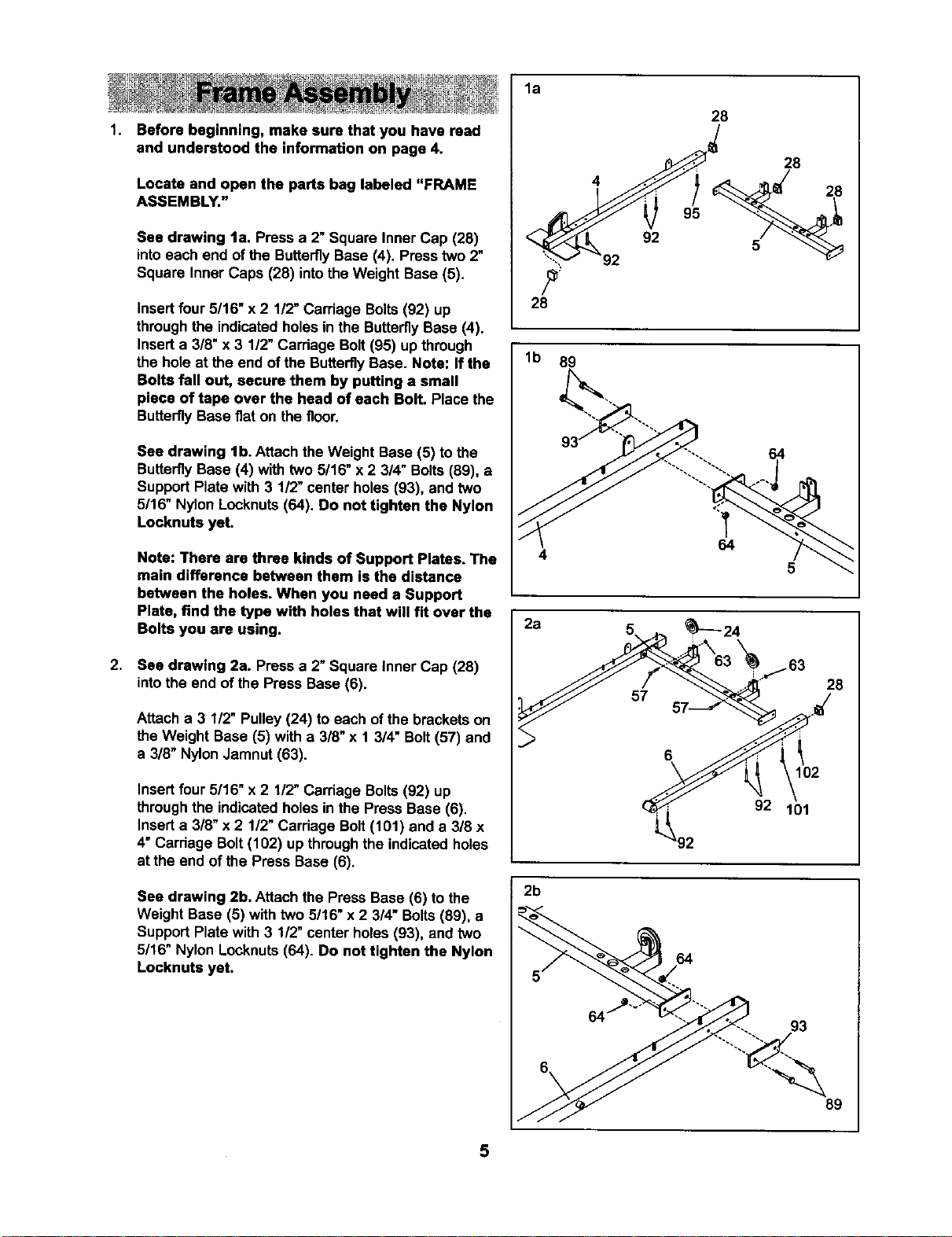
See drawing la. Press a 2" Square Inner Cap (28)
intoeach end of the ButterflyBase (4). Presstwo 2"
Square Inner Caps (28) intothe Weight Base (5).
Insertfour5/16" x 2 1/2"Carriage Bolts(92) up
through the indicatedholes inthe ButterflyBase (4).
Inserta 3/8" x 3 1/2" Carriage Bolt(95) up through
the hole at the end of the ButterflyBase. Note: If the
Bolts fall out, secure them by putting a small
piece of tape over the head of each Bolt. Place the
ButterflyBase fiat on the floor.
See drawing lb. Attach the Weight Base (5) to the
ButterflyBase (4) with two 5/16" x 2 3/4" Bolts(89), a
SupportPlate with 3 1/2" center holes (93), and two
5/16" Nylon Locknuts(64). Do not tighten the Nylon
Locknuts yet.
Note: There are three kinds of Support Plates. The
main difference between them is the distance
between the holes. When you need a Support
Plate, find the type with holes that will fit over the
Bolts you are using.
See drawing 2a. Pressa 2" Square Inner Cap (28)
intothe end of the Press Base (6).
Attach a 3 1/2" Pulley(24) to each of the brackets on
theWeight Base (5) with a 3/8"x 1 3/4" Bolt(57) and
a 318"NylonJamnut (63).
Insertfour 5/16" x 2 1/2" Carriage Bolts(92) up
throughthe indicatedholes in the Press Base (6).
Inserta 3/8" x 2 1/2"Carriage Bolt(101) and a 318x
4" Carriage Bolt(102) up throughthe indicated holes
at the end of the Press Base (6).
See drawing 2b. Attach the Press Base (6) to the
Weight Base (5) with two 5/16" x 2 3/4" Bolts(89), a
SupportPlate with 3 1/2" center holes (93), and two
5/16" Nylon Locknuts(64). Do not tighten the Nylon
Locknuts yet.
la
28
lb 89
2a
2b
28
4
92
64
5
28
102
92 101
64
93
89
5
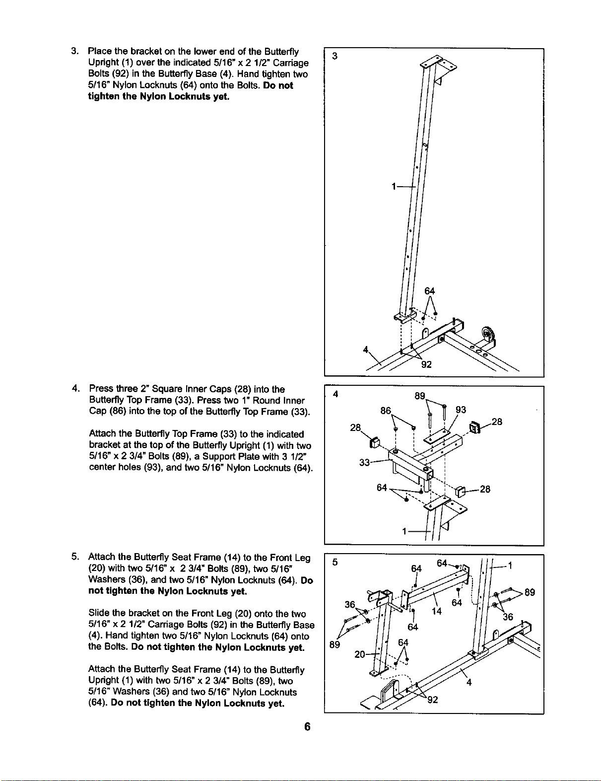
3. Place the bracket on the lowerend of the Butterfly
Upright (1) over the indicated5/16" x 2 1/2" Carriage
Bolts (92) in the Butterfly Base (4). Hand tighten two
5/16" Nylon Locknuts (64) onto the Bolts. Do not
tighten the Nylon Locknuts yet.
4,
Press three 2" Square Inner Caps (28) intothe
ButterflyTop Frame (33). Press two 1"Round Inner
Cap (86) intothe top of the ButterflyTop Frame (33).
Attach the Butterfly TopFrame (33) to the indicated
bracketat the top ofthe ButterflyUpright(1) withtwo
5/16" x 2 3/4" Bolts(89), a SupportPlate with 3 1/2"
center holes (93), and two 5/16" Nylon Locknuts(64).
5. Attach the ButterflySeat Frame (14) to the Front Leg
(20) with two 5/16" x 2 3/4" Bolts(89), two 5/16"
Washers (36), and two 5/16" Nylon Locknuts (64). Do
not tighten the Nylon Locknuts yet.
Slide the bracket on the Front Leg (20) ontothe two
5/16" x 2 1/2" Carriage Bolts(92) in the ButterflyBase
(4). Hand tighten two 5/16" Nylon Locknuts(64) onto
the Bolts. Do not tighten the Nylon Locknute yet,
Attach the ButterflySeat Frame (14) to the Butterfly
Upright(1) with two 5/16" x 2 3/4" Bolts(89), two
5/16" Washers (36) and two 5/16" Nylon Locknuts
(64). Do not tighten the Nylon Locknuts yet.
4
89
1
64
4\
92
8c
86
84 u
3 _28
6
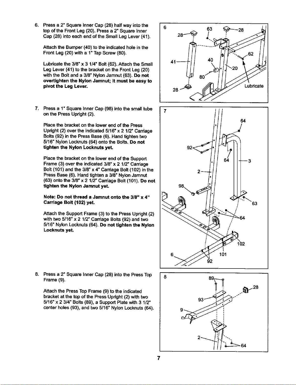
6. Press a 2" Square Inner Cap (28) half way intothe
top of the Front Leg (20), Press a 2"Square Inner
Cap (28) intoeach end of the Small Leg Lever (41).
Attach the Bumper (40) to the indicatedhole in the
Front Leg (20) with a 1"Tap Screw (80).
Lubricatethe 3/8" x 3 1/4" Bolt(62). Attach the Small
Leg Lever (41) tothe bracket on the Front Leg (20)
with the Boltand a 3/8" NylonJamnut(63). Do not
overtighten the Nylon Jamnut; it must be easy to
pivot the Leg Lever.
40
Lubricate
7.
Press a 1"Square Inner Cap (98) intothe smalltube
on the Press Upright(2).
Place the bracketon the lower endof the Press
Upright(2) over the indicated5/16" x 2 1/2" Carriage
Bolts(92) inthe Press Base (6). Hand tighten two
5/16" Nylon Locknuts(64) ontothe Bolts.Do not
tighten the Nylon Locknuts yet.
Place the bracketon the lower end of the Support
Frame (3) over the indicated3/8" x 2 1/2"Carriage
Bolt(101) and the 3/8" x 4" Carriage Bolt(102) in the
Press Base (6). Hand tighten a 3/8" NylonJamnut
(63) ontothe 3/8" x 2 1/2" Carriage Bolt(101). Do not
tighten the Nylon Jarnnut yet.
Note: Do not thread a Jamnut onto the 3/8" x 4"
Carriage Bolt (102) yet.
Attach the SupportFrame (3) to the Press Upright(2)
with two 5/16" x 2 1/2"Carriage Bolts(92) and two
5/16" Nylon Locknuts(64). Do not tighten the Nylon
Locknuts yet.
/
/
64
63
102
101
92
8.
Press a 2" Square Inner Cap (28) intothe PressTop
Frame (9).
Attach the Press TopFrame (9) tothe indicated
bracket at the top of the Press Upright(2) with two
5/16" x 2 3/4" Bolts(89), a SupportPlate with 3 1/2"
center holes (93), and two 5/16" Nylon Locknuts(64).
_> ._28
7
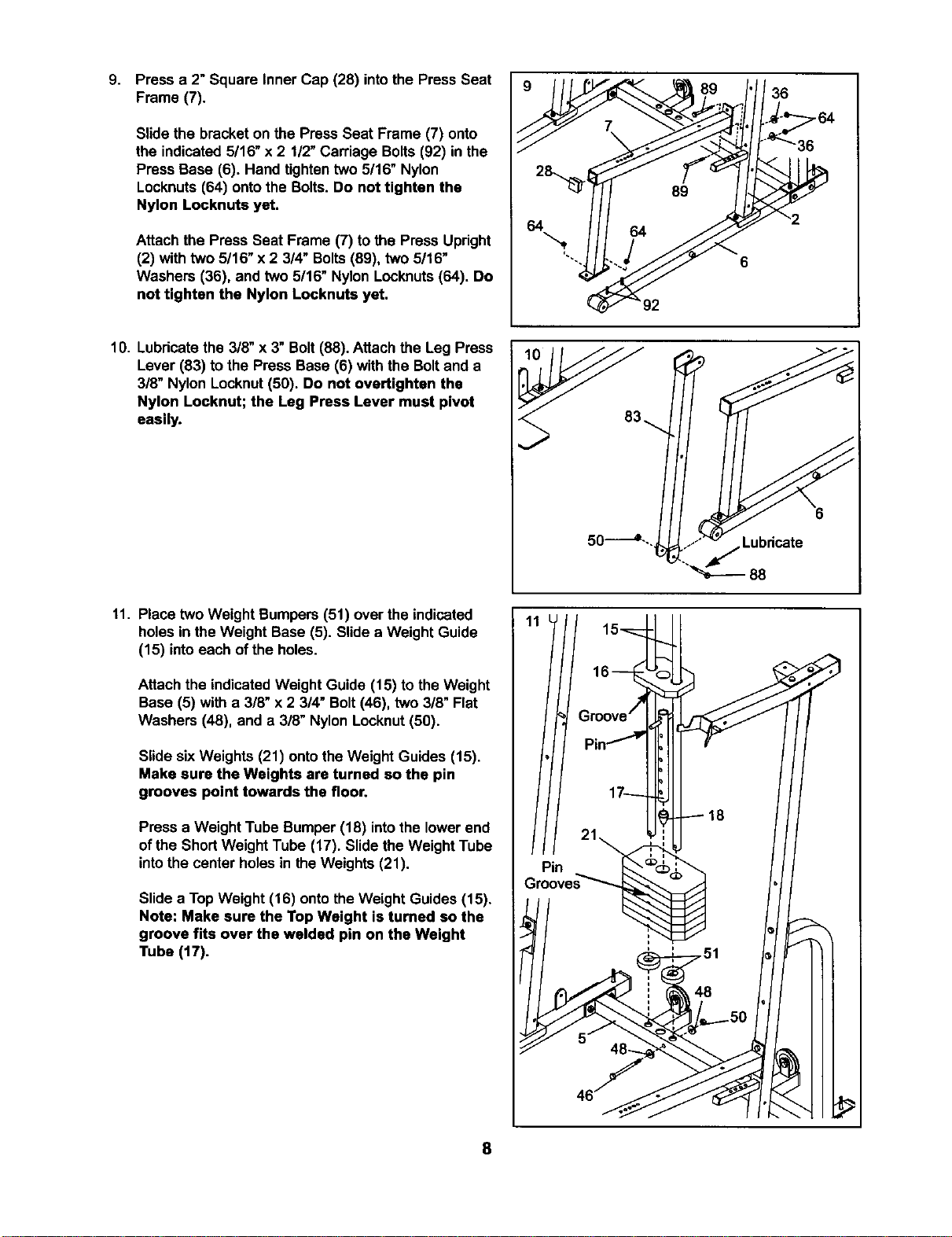
9.
Press a 2" Square Inner Cap (28) intothe Press Seat
Frame (7).
Slide the bracketon the Press Seat Frame (7) onto
the indicated 5/16" x 2 1/2"Carriage Bolts(92) in the
Press Base (6). Hand tightentwo 5/16" Nylon
Locknuts(64) ontothe Bolts. Do not tighten the
Nylon Locknuts yet.
Attach the Press Seat Frame (7) to the Press Upright
(2) withtwo 5/16" x 2 3/4" Bolts(89), two 5/16"
Washers (36), and two 5/16" Nylon Locknuts(64). Do
not tighten the Nylon Locknuts yet.
36
10. Lubricatethe 3/8" x 3"Bolt (88). Attach the Leg Press
Lever (83) to the Press Base (6) with the Boltand a
3/8" Nylon Locknut(50). Do not overtighten the
Nylon Locknut; the Leg Press Lever must pivot
easily.
11. Place two Weight Bumpers (51) over the indicated
holesin the Weight Base (5). Slidea Weight Guide
(15) intoeach of the holes.
Attach the indicatedWeight Guide (15) to the Weight
Base (5) with a 3/8" x 2 3/4" Bolt(46), two 3/8" Flat
Washers (48), and a 3/8" NylonLocknut (50).
Slide sixWeights (21) ontothe Weight Guides (15).
Make sure the Weights are turned so the pin
grooves point towards the floor.
Press a Weight Tube Bumper (18) intothe lowerend
of the ShortWeight Tube (17). Slide the Weight Tube
intothe center holesin the Weights (21).
Slide a TopWeight (16) onto theWeight Guides (15).
Note: Make sure the Top Weight is turned so the
groove fits over the welded pin on the Weight
Tube (17).
8

12. Place two Weight Bumpers (51) over the indicated
holes inthe Weight Base (5). Slide a Weight Guide
(15) intoeach ofthe holes.
Attach the indicatedWeight Guide (15) to the Weight
Base (5) with a 3/8" x 2 3/4" Bolt(46), two 3/8" Flat
Washers (48), and a 3/8" Nylon Locknut(50).
Slide ten Weights (21) ontothe Weight Guides (15).
Make sure the Weights are turned so the pin
grooves point towards the floor.
Press a Weight Tube Bumper (18) intothe lowerend
of the Long Weight Tube (70). Slidethe Weight Tube
intothe center holes inthe Weights (21).
Slide a TopWeight (16) ontothe Weight Guides (15).
Note: Make sure the Top Weight is tumed so the
groove fits over the welded pin on the Weight
Tube (70).
13. Place the Weight Top Frame (66) on the indicated
brackets on the Uprights(1 and 2). Note: The four
Weight Guides (15) must be behind the Weight
Top Frame, as shown in step 14.
Attach the Weight Top Frame (66) tothe ButterflyTop
Frame (33) with two 3/8" x 2 3/4" Bolts(46), a
Support Plate with 4"center holes(94), and two 3/8"
Nylon Locknuts(50). Do not tighten the Nylon
Locknuts yet.
Attach the Weight Top Frame (66) to the bracketon
the ButterflyUpright (1) with two 3/8"x 2 3/4" Bolts
(46), a SupportPlate with 2 1/2" center holes (34),
and two 3/8" Nylon Locknuts(50). Do not tighten the
Nylon Locknuts yet.
14. Attach the Weight TopFrame (66) tothe Press Top
Frame (9) with one 3/8" x 2 3/4" Bolt(46), a Support
Plate with 4"center holes(94), and a 3!8" Nylon
Locknut (50). Slide a 3 1/2" Pulley (24) with a Cable
Trap (25) ontoa 3/8" x 4" Bolt(78). Insertthe Bolt
throughthe SupportPlate (94) and hand tightena
3/8" Nylon Locknut(50) onto it.
Attach the Weight Top Frame (66) tothe bracket on
the Press Upright(2) withtwo 3/8" x 2 3/4" Bolts(46),
a SupportPlate with 2 1/2" center holes(34) and two
3/8" Nylon Locknuts(50). Do not tighten the Nylon
Locknuts yet.
9
12
Pin
51
5
13 34_46
46 ,. _¢U-o'_'=_._ 50
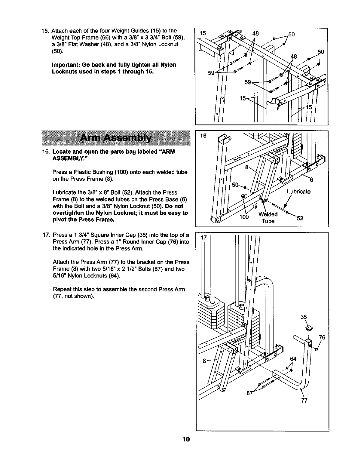
15. Attach each of the four Weight Guides (15) tothe
Weight Top Frame (66) with a 3/8" x 3 3/4" Bolt (59),
a 3/8" Flat Washer (48), and a 3/8" Nylon Locknut
(50).
Important: Go back and fully tighten all Nylon
Locknuts used in steps 1 through 15.
16. Locate and open the parts bag labeled "ARM
ASSEMBLY."
Press a Plastic Bushing(100) ontoeach welded tube
on the Press Frame (8).
Lubricatethe 3/8" x 8" Bolt(52). Attach the Press
Frame (8) tothe welded tubes on the Press Base (6)
with the Boltand a 3/8" NylonLocknut(50). Do not
overtighten the Nylon Locknut; it must be easy to
pivot the Press Frame,
17. Pressa 1 3/4" Square Inner Cap (35) intothe top of a
PressArm (77). Press a 1" Round Inner Cap (76) into
the indicatedholein the PressArm.
Attach the PressArm (77) to the bracket on the Press
Frame (8) with two 5/16" x 2 112"Bolts(87) and two
5/16" Nylon Locknuts(64).
Repeat this stepto assemble the second PressArm
(77, not shown).
15 48 50
Lubricate
52
35
64
77
10
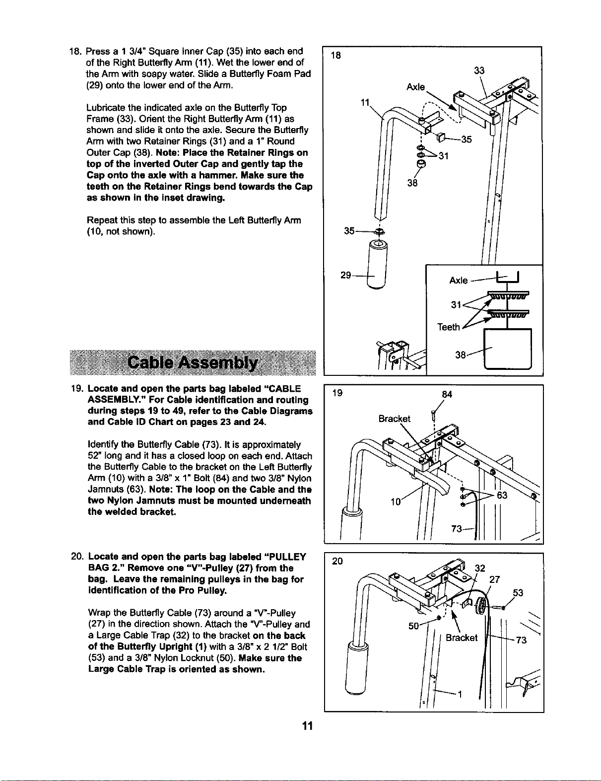
18. Press a 1 3/4" Square Inner Cap (35) into each end
of the Right Butterfly Arm (11). Wet the lower end of
the Arm with soapy water. Slide a Butterfly Foam Pad
(29) onto the lower end of the Arm.
Lubricatethe indicated axle on the ButterflyTop
Frame (33). Orientthe Right ButterflyArm (11) as
shownand slide itontothe axle. Secure the Butterfly
Arm with two Retainer Rings (31) and a 1"Round
Outer Cap (38). Note: Place the Retainer Rings on
top of the inverted Outer Cap and gently tap the
Cap onto the axle with a hammer. Make sure the
teeth on the Retainer Rings bend towards the Cap
as shown in the inset drawing.
Repeat this step to assemble the Left ButterflyArm
(10, not shown).
18
11
\
Axle
33
19. Locate and open the parts bag labeled "CABLE
ASSEMBLY." For Cable identification and routing
during steps 19 to 49, refer to the Cable Diagrams
and Cable ID Chart on pages 23 and 24.
Identify the ButterflyCable (73). It is approximately
52" long and ithas a closed loop on each end. Attach
the ButterflyCable to the bracket on the LeftButterfly
Arm (10) with a 3/8" x 1"Bolt(84) and two 3/8" Nylon
Jamnuts (63). Note: The loop on the Cable and the
two Nylon Jamnuta must be mounted underneath
the welded bracket.
19
Bracket
lOj
84
// 73-
20. Locate and open the parts bag labeled "PULLEY
BAG 2." Remove one "V"-Pulley (27) from the
bag. Leave the remaining pulleys in the bag for
identification of the Pro Pulley,
Wrap the ButterflyCable (73) around a "V'-Pulley
(27) inthe direction shown.Attach the "V"-Pulley and
a Large Cable Trap (32) to the bracket on the back
of the Butterfly Upright (1) witha 3/8" x2 1/2" Bolt
(53) and a 3/8" Nylon Locknut(50). Make sure the
Large Cable Trap is oriented as shown.
2O
' Bracket
"'_ 1
27
53
=J
11
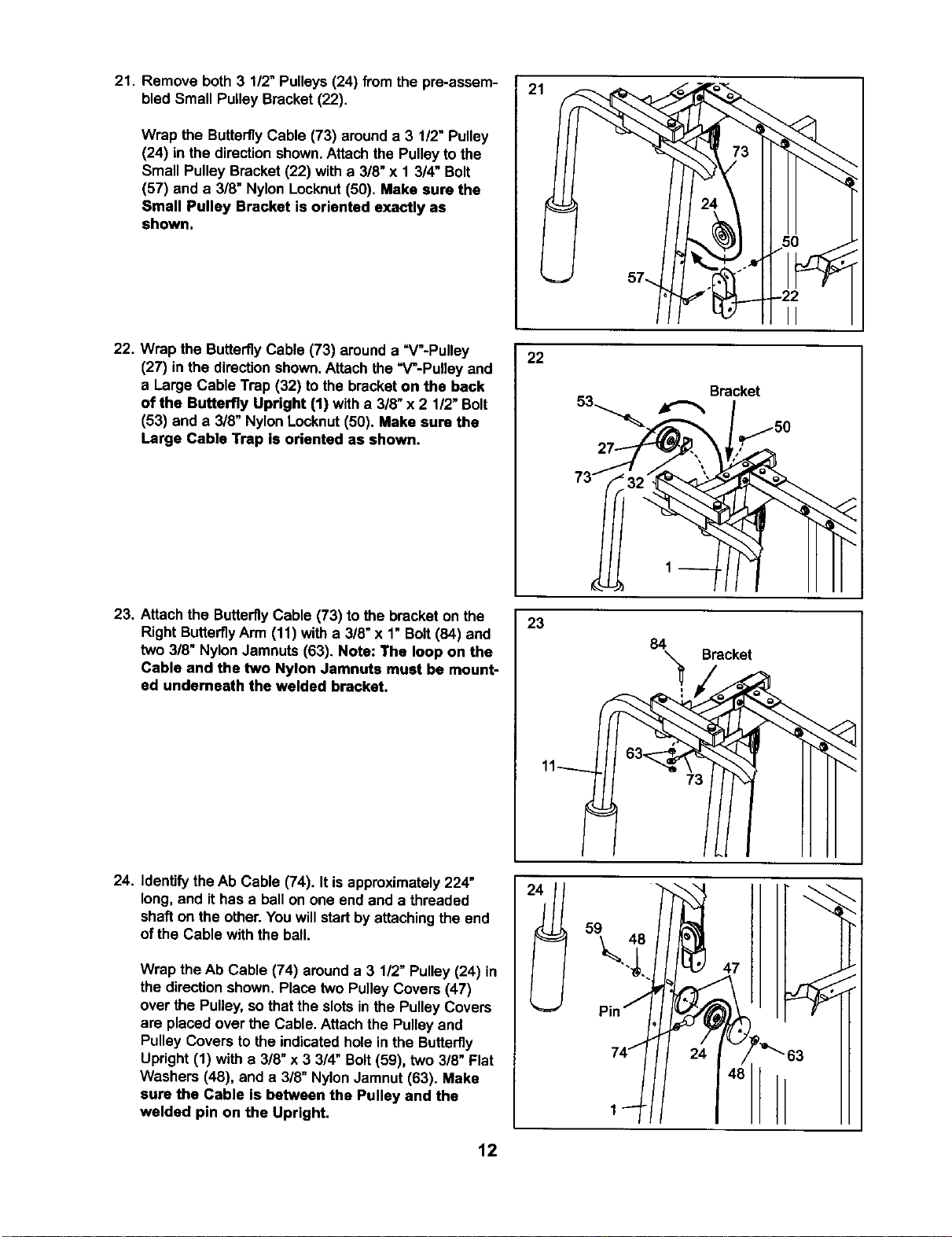
21. Remove both 3 112"Pulleys(24) from the pre-assem-
bled Small Pulley Bracket(22).
Wrap the Butterfly Cable (73) arounda 3 1/2" Pulley
(24) in the direction shown.Attach the Pulleyto the
Small Pulley Bracket (22) with a 3/8" x 1 3/4" Bolt
(57) and a 3/8" Nylon Locknut(50). Make sure the
Small Pulley Bracket is oriented exactly as
shown.
22. Wrap the ButterflyCable (73) arounda =V"-Pulley
(27) in the directionshown.Attach the =V-Pulley and
a Large Cable Trap (32) to the bracketon the back
of the Butterfly Upright (1) witha 3/8" x 2 1/2"Bolt
(53) and a 3/8" NylonLocknut(50). Make aura the
Large Cable Trap is oriented as shown.
23. Attach the ButterflyCable (73) to the bracket on the
Right ButterflyArm (11) witha 3/8" x 1"Bolt(84) and
two 3/8" NylonJamnuts (63). Note: The loop on the
Cable and the two Nylon Jamnuta must be mount-
ed undemeath the welded bracket.
24. Identifythe Ab Cable (74). It isapproximately224"
long, and ithas a ballon one end and a threaded
shaft on the other. Youwill startbyattaching the end
of the Cable withthe ball.
Wrap the Ab Cable (74) arounda 3 1/2" Pulley (24) in
the directionshown. Place two Pulley Covers(47)
over the Pulley,so that the slotsin the PulleyCovers
are placedover the Cable. Attach the Pulley and
Pulley Covers to the indicatedhole in the Butterfly
Upright (1) with a 3/8" x 3 3/4" Bolt(59), two 3/8" Flat
Washers (48), and a 3/8" NylonJamnut(63). Make
sure the Cable is between the Pulley and the
welded pin on the Upright.
2.
1
22
Bracket
l
73 _
23
84 Bracket
47
_"63
12
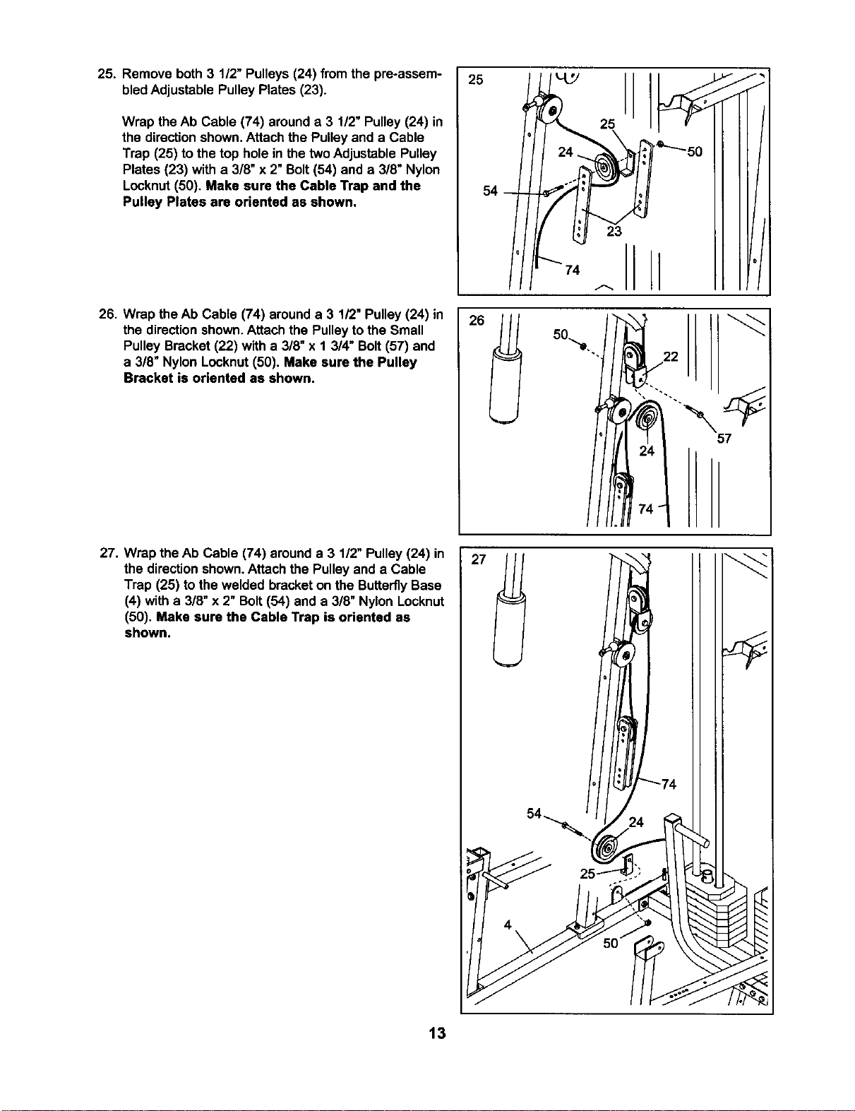
25. Remove both 3 1/2" Pulleys (24) from the pre-assem-
bledAdjustable Pulley Plates (23).
Wrap the Ab Cable (74) arounda 3 1/2" Pulley (24) in
the directionshown. Attach the Pulleyand a Cable
Trap (25) to the top holein thetwoAdjustable Pulley
Plates (23) with a 3/8" x 2" Bolt(54) and a 3/8" Nylon
Locknut(50). Make sure the Cable Trap and the
Pulley Plates are oriented as shown.
26. Wrap the Ab Cable (74) arounda 3 1/2" Pulley(24) in
the directionshown,Attach the Pulleytothe Small
Pulley Bracket (22) with a 3/8" x 1 3/4" Bolt(57) and
a 3/8" Nylon Locknut(50). Make sure the Pulley
Bracket is oriented as shown.
27. Wrap theAb Cable (74) arounda 3 1/2" Pulley(24) in
the directionshown.Attach the Pulley and a Cable
Trap (25) to the welded bracketon the ButterflyBase
(4) with a 3/8"x 2" Bolt(54) and a 3/8" Nylon Locknut
(50). Make sure the Cable Trap is oriented as
shown.
25
25
26
23
74 A
J
J
57
t3
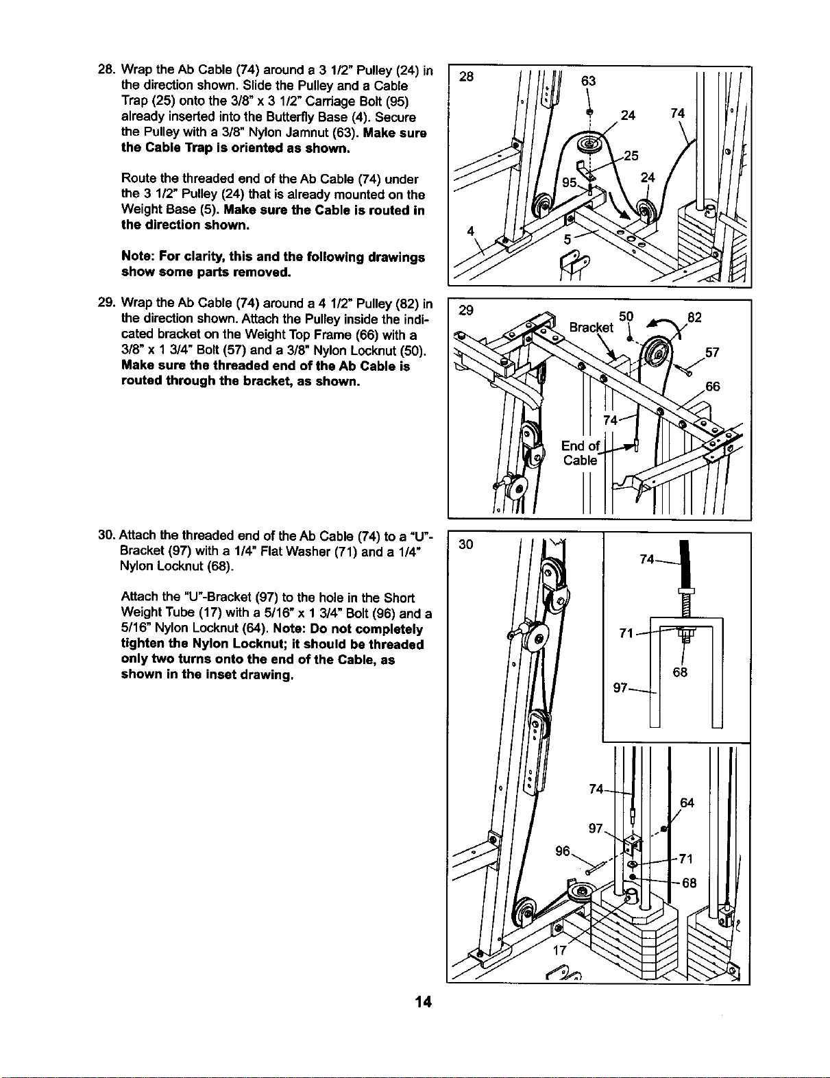
28. Wrap the Ab Cable (74) arounda 3 1/2" Pulley (24) in
the direction shown. Slidethe Pulleyand a Cable
Trap (25) ontothe 3/8" x 3 1/2"Carriage Bolt(95)
already insertedintothe ButterflyBase (4). Secure
the Pulleywith a 3/8" Nylon Jamnut (63). Make sure
the Cable Trap is oriented as shown.
Route the threaded end of theAb Cable (74) under
the 3 1/2" Pulley (24) that isalready mounted on the
Weight Base (5). Make sure the Cable is routed in
the direction shown.
Note: For clarity, this and the following drawings
show some parts removed.
29. Wrap the h,bCable (74) around a 4 1/2" Pulley(82) in
the direction shown.Attachthe Pulley insidethe indi-
cated bracket on the Weight Top Frame (66) with a
3/8" x 1 3/4" Bolt(57) and a 3/8" Nylon Locknut(50).
Make sure the threaded end of the Ab Cable is
routed through the bracket, as shown.
30. Attach the threaded end of theAb Cable (74) to a =U'-
Bracket (97) with a 1/4" Flat Washer (71) and a 1/4"
Nylon Locknut (68).
Attach the "U"-Bracket(97) to the hole in the Short
Weight Tube (17) with a 5/16" x 1 3/4" Bolt(96) and a
5/16" Nylon Locknut(64). Note: Do not completely
tighten the Nylon Locknut; it should be threaded
only two turns onto the end of the Cable, as
shown in the inset drawing.
14
28
63
I 24
I
74
29
50
82
/66
./
./
3O
68
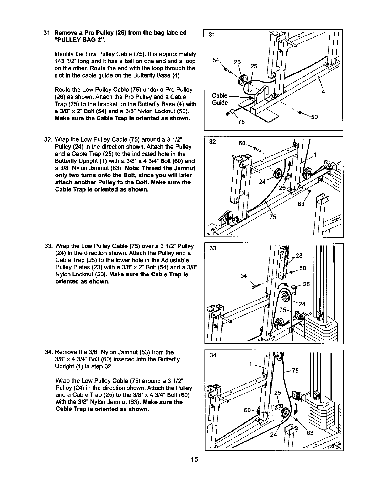
31. Remove a Pro Pulley (26) from the bag labeled
"PULLEY BAG 2".
Identifythe Low Pulley Cable (75). It isapproximately
143 1/2"long and it has a ball on one end and a loop
on the other. Route the end with the loopthroughthe
slotin the cable guide on the ButterflyBase (4).
Routethe Low Pulley Cable (75) undera Pro Pulley
(26) as shown.Attach the Pro Pulleyand a Cable
Trap (25) to the bracket on the ButterflyBase (4) with
a 3/8" x 2" Bolt (54) and a 3/8" Nylon Locknut(50).
Make sure the Cable Trap is oriented as shown•
31
Guide
25
75
32. Wrap the Low PulleyCable (75) arounda 3 1/2"
Pulley (24) inthe directionshown.Attach the Pulley
and a Cable Trap (25) to the indicatedhole in the
ButterflyUpright(1) with a 3/8" x 4 3/4" Bolt (60) and
a 3/8" NylonJamnut (63). Note: Thread the Jamnut
only two turns onto the Bolt, since you will later
attach another Pulley to the Bolt. Make sure the
Cable Trap is oriented as shown.
32
63
33. Wrap the Low PulleyCable (75) over a 3 1/2"Pulley
(24) inthe directionshown.Attach the Pulley and a
Cable Trap (25) to the lower hole inthe Adjustable
Pulley Plates (23) with a 3/8" x 2" Bolt(54) and a 3/8"
Nylon Locknut(50). Make sure the Cable Trap is
oriented as shown.
33
54
\
34. Remove the 3/8" NylonJamnut (63) from the
3/8" x 4 3/4" Bolt(60) inserted intothe Butterfly
Upright (1) in step 32.
Wrap the Low Pulley Cable (75) arounda 3 1/2"
Pulley (24) inthe directionshown.Attach the Pulley
and a Cable Trap (25) to the 3/8" x 4 3/4" Bolt(60)
with the 3/8" NylonJamnut (63). Make sure the
Cable Trap is oriented as shown.
34
15
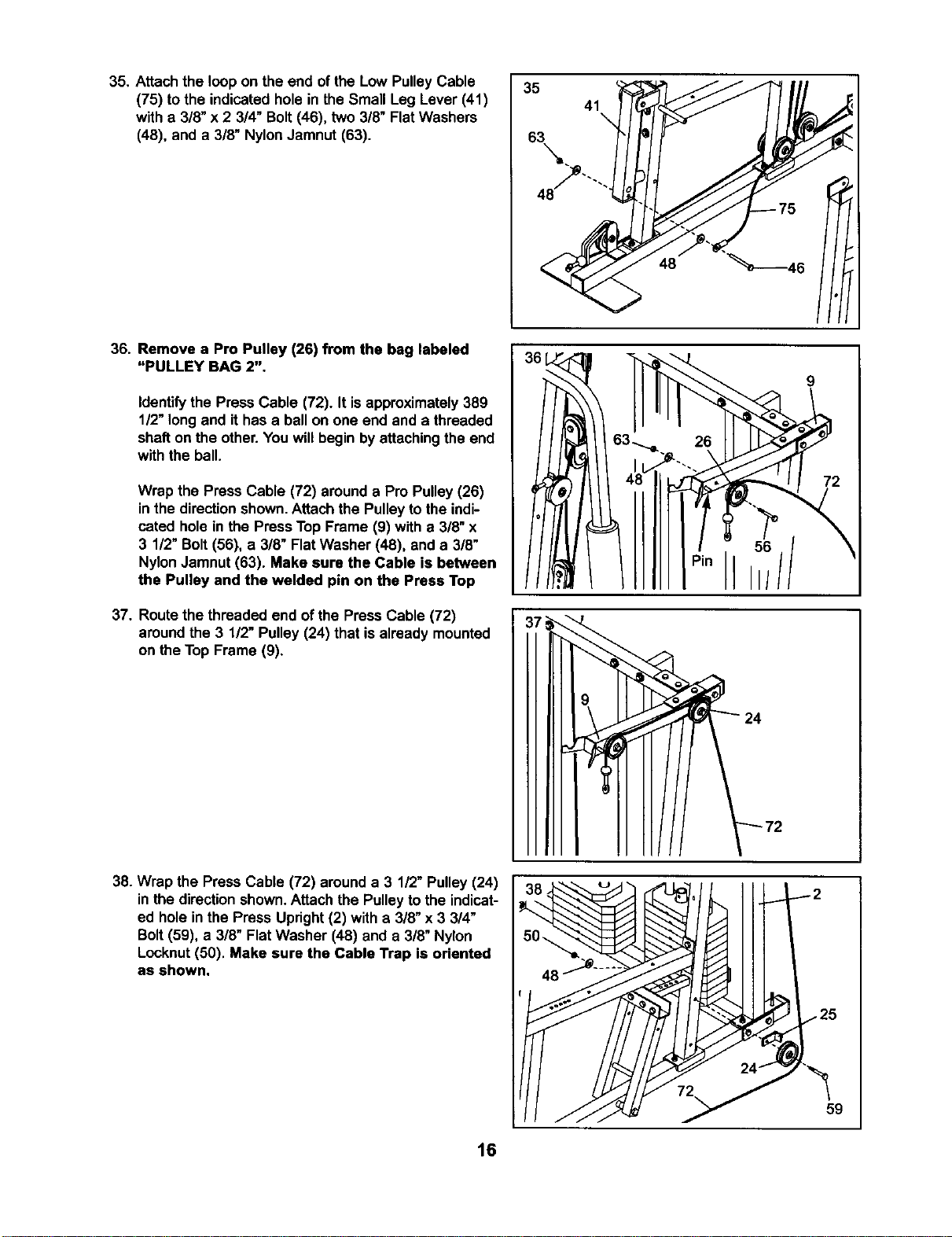
35. Attachthe loop on the end of the Low PulleyCable
(75) to the indicatedhole in the Small Leg Lever (41)
with a 3/8" x 2 3/4" Bolt(46), two 3/8" Flat Washers
(48), and a 3/8" NylonJamnut (63).
35
41
48
36. Remove a Pro Pulley (26) from the bag labeled
"PULLEY BAG 2".
Identifythe Press Cable (72). It isapproximately389
1/2"long and it has a ball on one end and a threaded
shaft on the other. You willbegin by attachingthe end
with the ball.
Wrap the Press Cable (72) arounda Pro Pulley(26)
inthe directionshown.Attach the Pulleyto the indi-
cated hole in the Press Top Frame (9) with a 3/8" x
3 1/2" Bolt (56), a 3/8" Flat Washer (48), and a 3/8"
NylonJamnut (63). Make sure the Cable is between
the Pulley and the welded pin on the Press Top
37. Routethe threaded end of the Press Cable (72)
aroundthe 3 1/2" Pulley (24) that is already mounted
on the Top Frame (9).
26
38. Wrap the Press Cable (72) arounda 3 1/2" Pulley (24)
in the directionshown.Attach the Pulleyto the indicat-
ed holein the Press Upright(2) with a 3/8" x3 3/4"
Bolt(59), a 3/8" Flat Washer (48) and a 3/8" Nylon
Locknut(50). Make sure the Cable Trap is oriented
as shown.
59
16
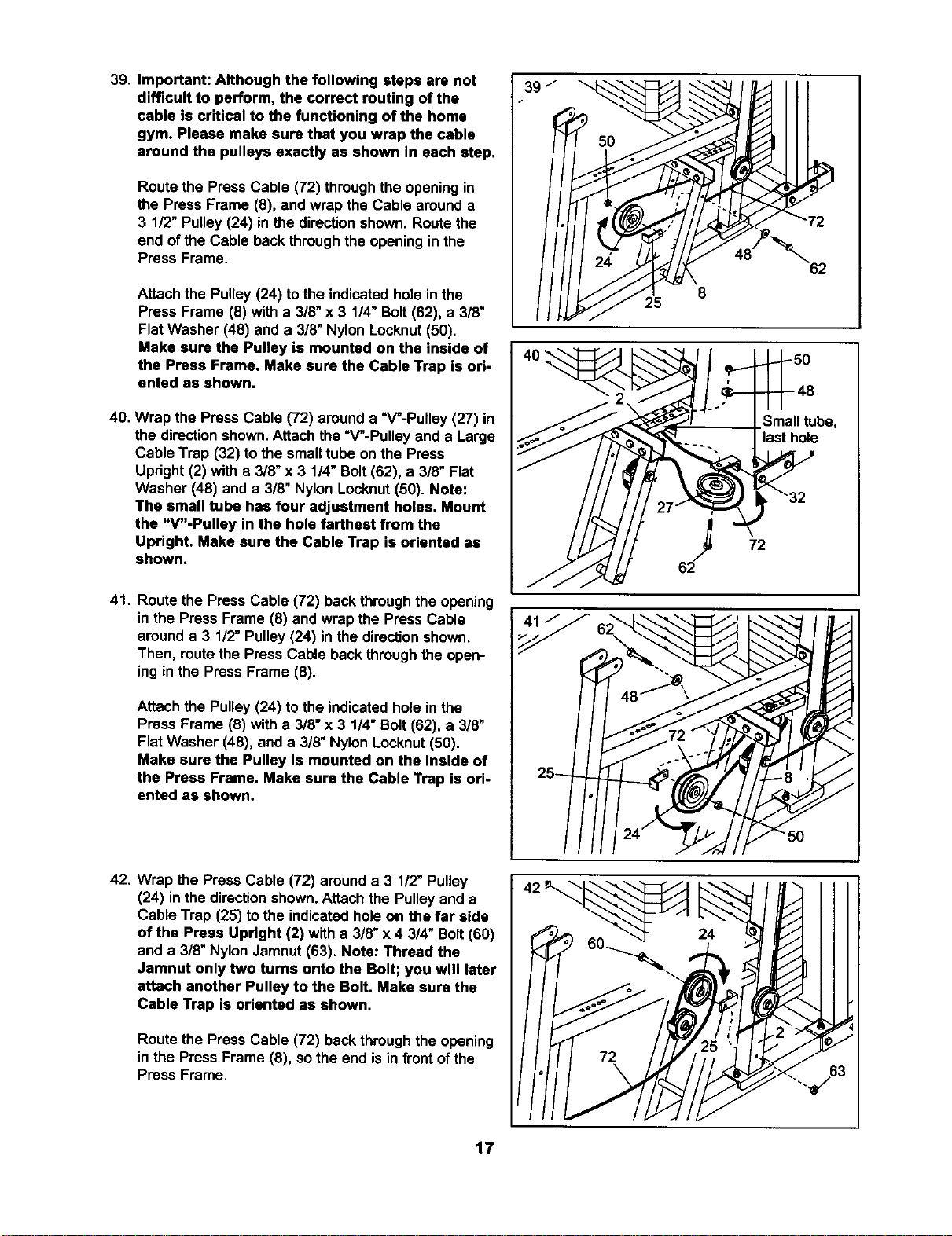
39. Important: Although the following steps are not
difficult to perform, the correct routing of the
cable is critical to the functioning of the home
gym. Please make sure that you wrap the cable
around the pulleys exactly as shown in each step.
Route the Press Cable (72) throughthe opening in
the Press Frame (8), and wrap the Cable around a
3 1/2" Pulley (24) in the directionshown. Routethe
end of the Cable backthroughthe opening inthe
Press Frame.
Attach the Pulley(24) tothe indicatedhole inthe
Press Frame (8) with a 3/8" x 3 1/4" Bolt(62), a 3/8"
Flat Washer (48) and a 3/8" Nylon Locknut(50).
Make sure the Pulley is mounted on the inside of
the Press Frame. Make sure the Cable Trap is ori-
ented as shown.
40. Wrap the Press Cable (72) arounda =V"-Pulley (27) in
the directionshown.Attach the =V'-Pulleyand a Large
Cable Trap (32) tothe small tube on the Press
Upright(2) with a 3/8" x 3 1/4"Bolt(62), a 3/8" Flat
Washer (48) and a 3/8" Nylon Locknut(50). Note:
The small tube has four adjustment holes. Mount
the "V"-Pulley in the hole farthest from the
Upright. Make sure the Cable Trap is oriented as
shown.
41. Route the Press Cable (72) back throughthe opening
in the Press Frame (8) and wrap the Press Cable
arounda 3 1/2"Pulley (24) in the directionshown.
Then, routethe Press Cable backthroughthe open-
ing in the Press Frame (8).
Attach the Pulley (24) to the indicatedhole in the
Press Frame (8) with a 3/8" x 3 1/4"Bolt (62), a 3/8"
Flat Washer (48), and a 3/8" Nylon Locknut(50).
Make sure the Pulley is mounted on the inside of
the Press Frame. Make sure the Cable Trap is ori-
ented as shown.
39 /
40
25
62
Small tube,
"last hole
72
fj
J
J
J
42. Wrap the Press Cable (72) arounda 3 112"Pulley
(24) in the directionshown.Attach the Pulley and a
Cable Trap (25) to the indicatedhole on the far side
of the Press Upright (2) with a 3/8" x4 3/4" Bolt(60)
and a 3/8" Nylon Jamnut (63). Note: Thread the
Jamnut only two turns onto the Bolt; you will later
attach another Pulley to the Bolt. Make sure the
Cable Trap is oriented as shown.
Route the Press Cable (72) backthroughthe opening
in the Press Frame (8), sothe end isin frontof the
Press Frame.
IL
f/t
f.,I
f..I
f_,d
F .
A
17
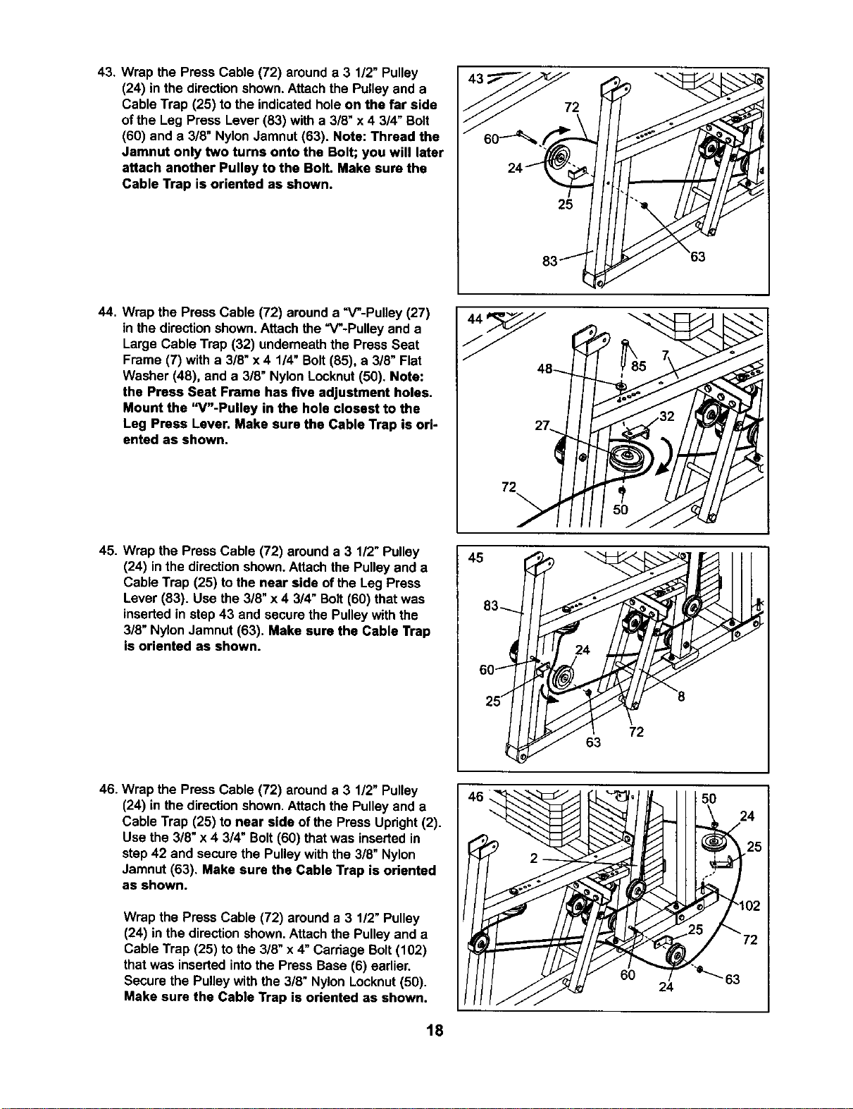
43. Wrap the Press Cable (72) arounda 3 1/2" Pulley
(24) in the direction shown. Attach the Pulleyand a
Cable Trap (25) to the indicatedholeon the far side
ofthe Leg Press Lever (83) with a 3/8" x4 3/4" Bolt
(60) and a 3/8" NylonJamnut (63). Note: Thread the
Jamnut only two tums onto the Bolt; you will later
attach another Pulley to the Bolt. Make sure the
Cable Trap is oriented as shown.
2
25
44. Wrap the Press Cable (72) arounda "V-Pulley (27)
in the directionshown.Attach the "V-Pulley and a
Large Cable Trap (32) underneath the Press Seat
Frame (7) with a 3/8" x 4 1/4" Bolt (85), a 3/8" Flat
Washer (48), and a 3/8" Nylon Locknut(50). Note:
the Press Seat Frame has five adjustment holes.
Mount the "V"-Pulley in the hole closest to the
Leg Press Lever. Make sure the Cable Trap is ori-
ented as shown.
72
45. Wrap the Press Cable (72) around a 3 1/2"Pulley
(24) in the directionshown.Attach the Pulleyand a
Cable Trap (25) to the near side of the Leg Press
Lever (83). Use the 3/8" x 4 3/4" Bolt(60) that was
inserted in step 43 and secure the Pulleywith the
3/8" Nylon Jamnut (63). Make sure the Cable Trap
is oriented as shown.
45
83-,_
60_
25/
72
63
46. Wrap the Press Cable (72) arounda 3 1/2" Pulley
(24) in the directionshown. Attachthe Pulleyand a
Cable Trap (25) to near side of the Press Upright(2).
Use the 3/8" x 4 3/4" Bolt(60) thatwas inserted in
step 42 and secure the Pulley withthe 3/8" Nylon
Jamnut (63). Make sure the Cable Trap is oriented
as shown.
Wrap the Press Cable (72) arounda 3 1/2" Pulley
(24) in the direction shown.Attach the Pulleyand a
Cable Trap (25) to the 3/8" x 4" Carriage Bolt(102)
that was inserted intothe Press Base (6) earlier.
Secure the Pulleywith the 3/8" Nylon Locknut(50).
Make sure the Cable Trap is oriented as shown.
46 " ' 50 242
18
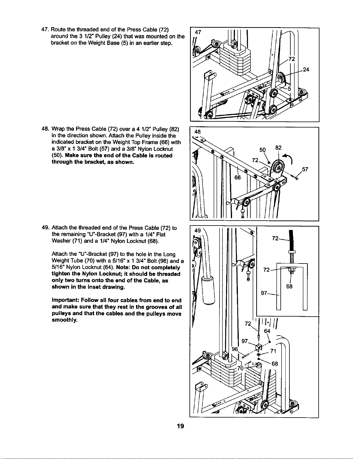
47. Route the threaded end of the Press Cable (72)
aroundthe 3 1/2" Pulley (24) that was mounted on the
bracket on the Weight Base (5) in an earlier step.
47
48. Wrap the Press Cable (72) over a 4 1/2" Pulley(82)
in the directionshown.Attach the Pulley insidethe
indicatedbracket on theWeight TopFrame (66) with
a 3/8" x 1 3/4" Bolt (57) and a 3/8" Nylon Locknut
(50). Make sure the end of the Cable is routed
through the bracket, as shown.
48
50 82
49. Attach the threaded end ofthe Press Cable (72) to
the remaining=U"-Bracket (97) with a 1/4" Flat
Washer (71) and a 114"Nylon Locknut(68).
Attach the =U"-Bracket (97) to the hole in the Long
Weight Tube (70) with a 5/16" x 1 3/4" Bolt(96) and a
5/16" Nylon Locknut(64). Note: Do not completely
tighten the Nylon Locknut; it should be threaded
only two turns onto the end of the Cable, as
shown in the inset drawing.
Important: Follow all four cables from end to end
and make sure that they rest in the grooves of all
pulleys and that the cables and the pulleys move
smoothly.
72
68
19
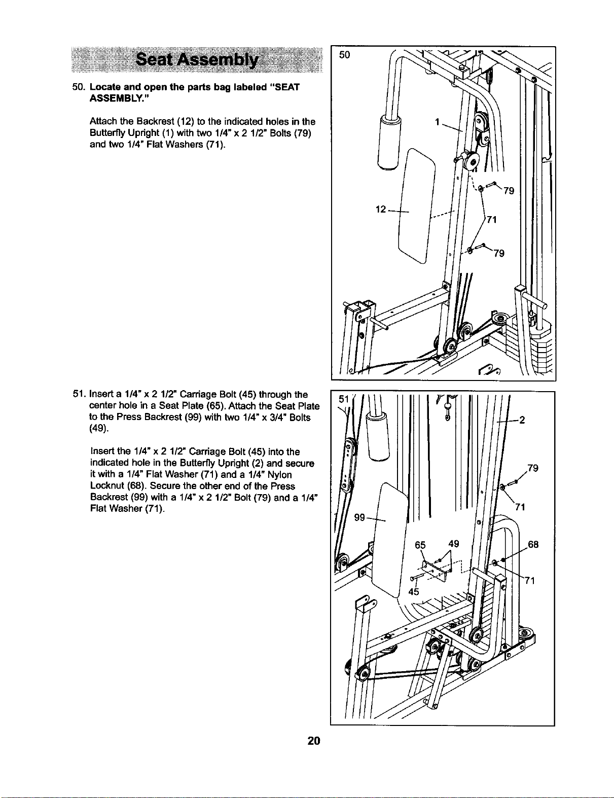
50. Locate and open the parts bag labeled "SEAT
ASSEMBLY."
Attach the Backrest(12) tothe indicatedholesin the
ButterflyUpright(1) withtwo 1/4"x 2 1/2" Bolts(79)
and two 114"Flat Washers (71).
51. Inserta 1/4"x 2 1/2" Carriage Bolt(45) throughthe
center hole in a Seat Plate (65). Attachthe Seat Plate
to the Press Backrest (99) with two 1/4" x 3/4" Bolts
(49).
Insertthe 1/4" x 2 1/2" Carriage Bolt(45) intothe
indicatedhole inthe ButterflyUpright(2) and secure
itwith a 1/4" Flat Washer (71) and a 1/4" Nylon
Locknut(68). Secure the other end of the Press
Backrest (99) with a 1/4"x 2 1/2" Bolt(79) and a 1/4"
Flat Washer (71).
50
49
71
2O
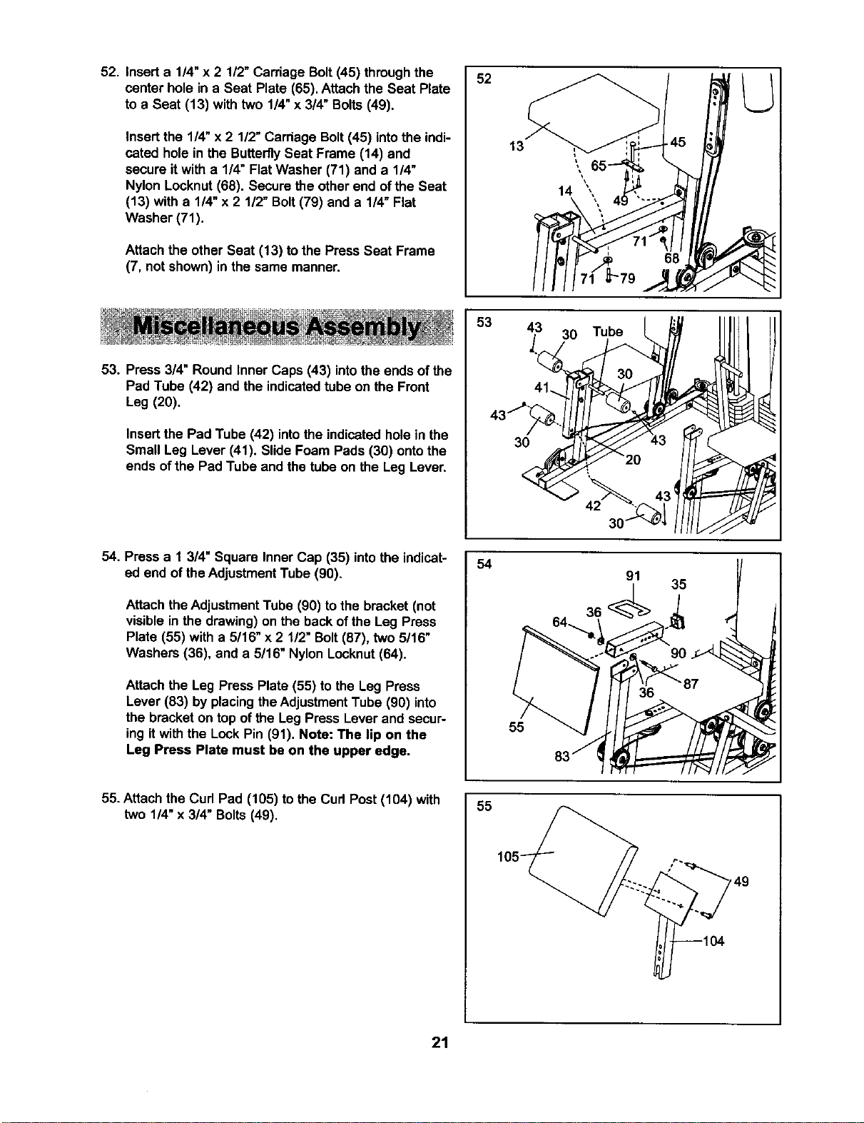
52. Inserta 1/4"x 2 112"Carriage Bolt(45) throughthe
center hole in a Seat Plate (65). Attachthe Seat Plate
to a Seat (13) with two 1/4"x 3/4" Bolts (49),
Insert the 1/4" x 2 1/2" Carriage Bolt(45) intothe indi-
cated hole in the ButterflySeat Frame (14) end
secure it with a 1/4" Flat Washer (71) and a 1/4"
Nylon Locknut (68). Secure the other end of the Seat
(13) with a 1/4" x 2 1/2" Bolt (79) and a 1/4" Flat
Washer (71).
Attach the other Seat (13) to the Press Seat Frame
(7, not shown) in the same manner.
52
53. Press 3/4" Round Inner Caps (43) into the ends of the
Pad Tube (42) and the indicatedtube on the Front
Leg (20),
Insertthe Pad Tube (42) intothe indicated holein the
Small Leg Lever (41). Slide Foam Pads (30) ontothe
ends of the Pad Tube and the tube on the Leg Lever.
53
43 30
30
Tube
54. Press a 1 3/4" Square Inner Cap (35) intothe indicat-
ed end of theAdjustmentTube (90).
Attach theAdjustment Tube (90) to the bracket (not
visible inthe drawing)on the backof the Leg Press
Plate (55) with a 5/16" x2 1/2" Bolt(87), two 5/16"
Washers (36), and a 5/16" Nylon Locknut(64).
Attach the Leg Press Plate (55) to the Leg Press
Lever (83) byplacingthe AdjustmentTube (90) into
the bracket on top ofthe Leg Press Lever and secur-
ing itwith the Lock Pin (91). Note: The lip on the
Leg Press Plate must be on the upper edge.
54
55
35
55. Attach the Curl Pad (105) to the Cud Post(104) with
two 1/4" x 3/4" Bolts(49),
55
21
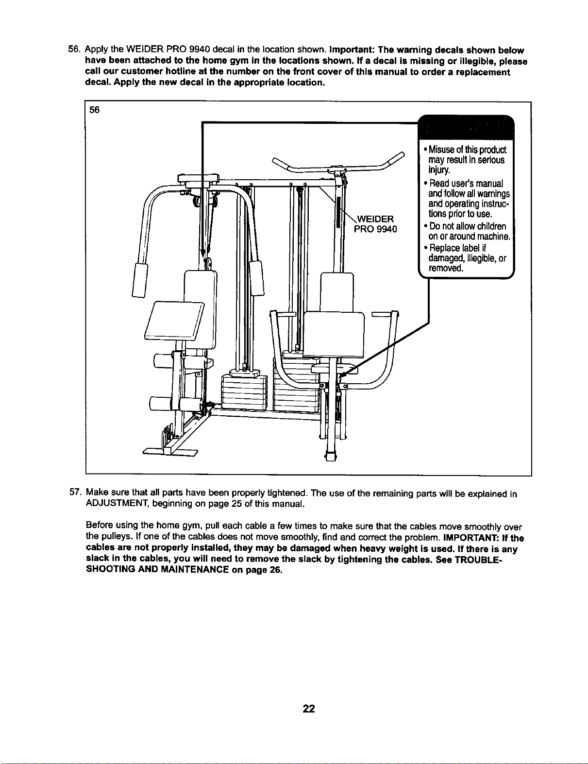
56. Apply the WELDER PRO 9940 decal in the location shown. Important: The warning decals shown below
have been attached to the home gym in the locations shown. If a decal is missing or illegible, please
call our customer hotline at the number on the front cover of this manual to order a replacement
decal. Apply the new decal in the appropriate location.
56
mayresultinserious
injury.
• Readuser'smanual
andfollowallwarnings
andoperatinginstruc-
tionspriortouse.
• Donotallowchildren
onoraroundmachine.
• Replacelabelif
damaged,illegible,or
removed.
57. Make sure that all parts have been properlytightened. The use ofthe remainingparts willbe explained in
ADJUSTMENT, beginningon page 25 of this manual.
Before usingthe home gym, pulleach cable a few timesto make sure thatthe cables move smoothlyover
the pulleys. Ifone of the cables does not move smoothly,find andcorrectthe problem.IMPORTANT: If the
cables are not properly installed, they may be damaged when heavy weight is used. If there is any
slack in the cables, you will need to remove the slack by tightening the cables. See TROUBLE-
SHOOTING AND MAINTENANCE on page 26.
22
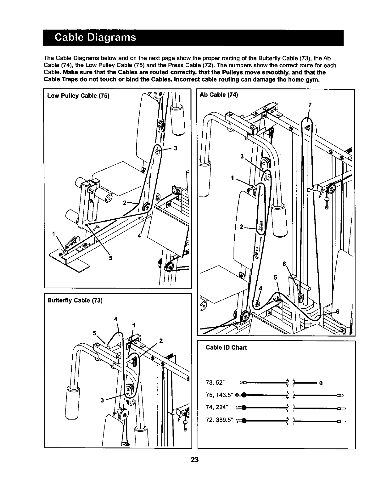
The Cable Diagrams below and on the next page show the properroutingof the ButterflyCable (73), the Ab
Cable (74), the Low Pulley Cable (75) and the Press Cable (72). The numbersshow the correctroute for each
Cable. Make sure that the Cables are routed correctly, that the Pulleys move smoothly, and that the
Cable Traps do not touch or bind the Cables. Incorrect cable routing can damage the home gym.
Low Pulley Cable (75)
Butterfly Cable (73)
4
1
5
2
Ab Cable (74)
Cable ID Chart
73, 52" _ 5-
75, 143.5" _ 5- 5-
74, 224" _ "r
72, 389.5" _c_ _"_ _=
5- 'r
23
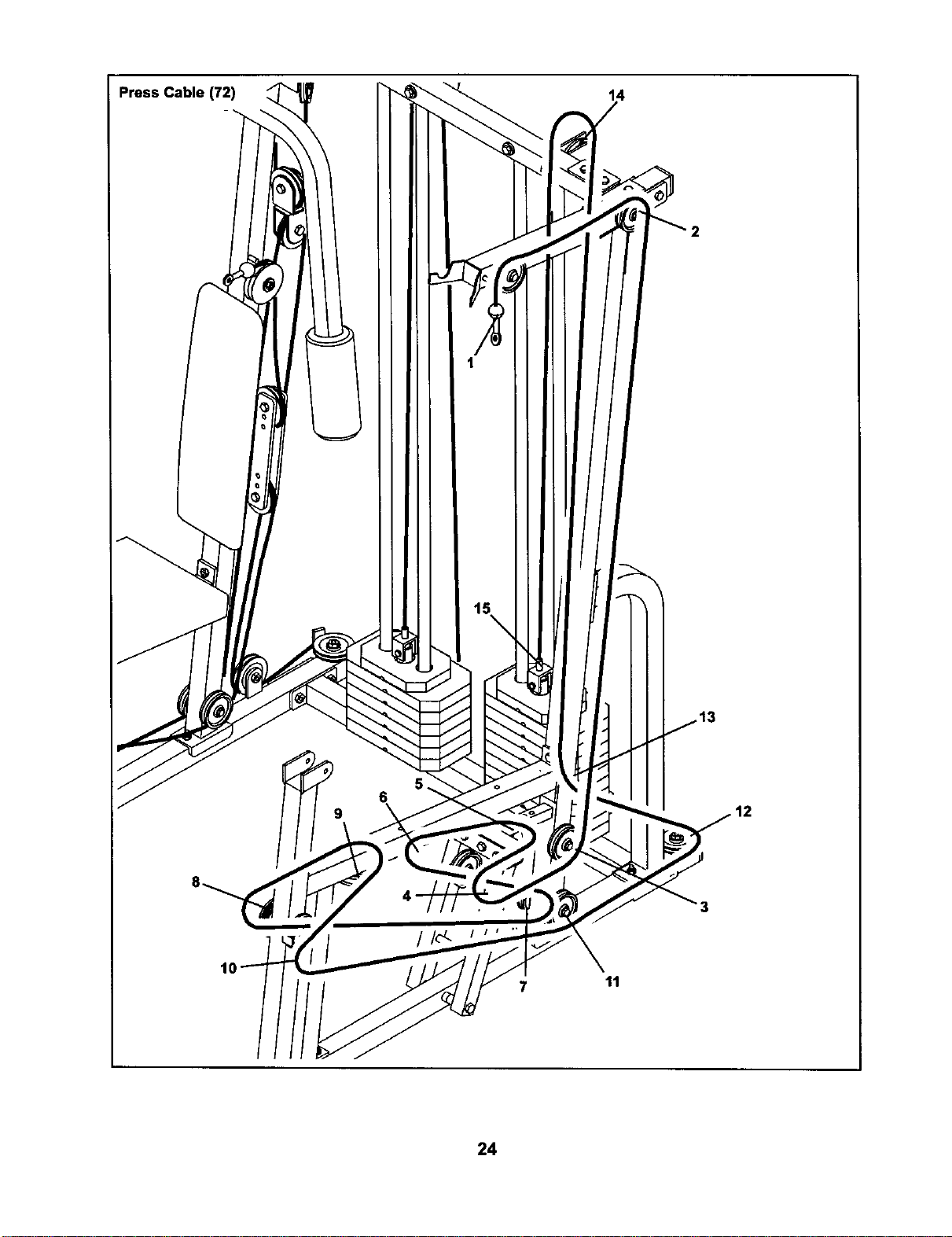
Press Cable (72)
14
5.
6
9
/
7 11
24
The instructionsbelowdescdbe howeach partofthe home gym can be adjusted.Refer to the exercise poster
accompanyingthis manual to see how the home gym shouldbe set up for each exercise. IMPORTANT: When
using an attachment, make sure it is in the correct starting position for the exercise to be performed. If
there is any slack in the cables or chain as an exercise is performed, the effectiveness of the exercise
will be reduced.
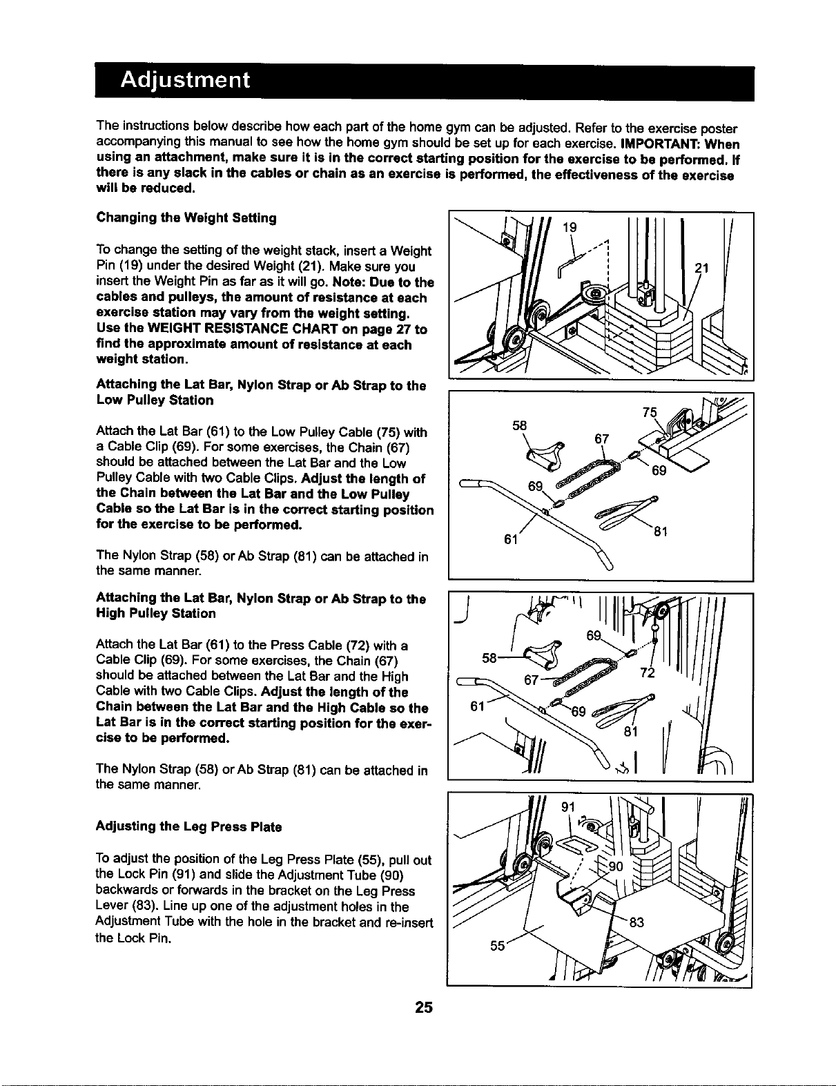
Changing the Weight Setting
To changethe settingof theweight stack, inserta Weight
Pin (19) under the desired Weight (21). Make sure you
insertthe Weight Pin as far as itwillgo. Note: Due to the
cables and pulleys, the amount of resistance at each
exercise station may vary from the weight setting.
Use the WEIGHT RESISTANCE CHART on page 27 to
find the approximate amount of resistance at each
weight station.
Attaching the Lat Bar, Nylon Strap crAb Strap to the
Low Pulley Station
Attach the Lat Bar (61) to the Low PulleyCable (75) with
a Cable Clip (69). For some exercises, the Chain (67)
shouldbe attached between the Lat Bar and the Low
PulleyCable with two Cable Clips. Adjust the length of
the Chain between the LSt Bar and the Low Pulley
Cable so the Lat Bar is in the correct starting position
for the exercise to be performed.
The Nylon Strap (58) or Ab Strap (81) can be attached in
the same manner.
19
58
61
75
67
Attaching the Lat Bar, Nylon Strap or Ab Strap to the
High Pulley Station
Attach the Lat Bar (61) to the Press Cable (72) with a
Cable Clip (69). For some exercises,the Chain (67)
shouldbe attached between the Lat Bar and the High
Cable with two Cable Clips.Adjust the length of the
Chain between the Let Bar end the High Cable so the
Lat Bar is in the correct starting position for the exer-
cise to be performed.
The Nylon Strap (56) orAb Strap (81) can be attached in
the same manner.
Adjusting the Leg Press Plate
To adjust the positionof the Leg Press Plate (55), pull out
the Lock Pin (91) and slidethe AdjustmentTube (90)
backwardsor forwards in the bracket on the Leg Press
Lever (83). Line up one of the adjustmentholes inthe
AdjustmentTube with the hole in the bracketand re-insert
the Lock Pin.
25
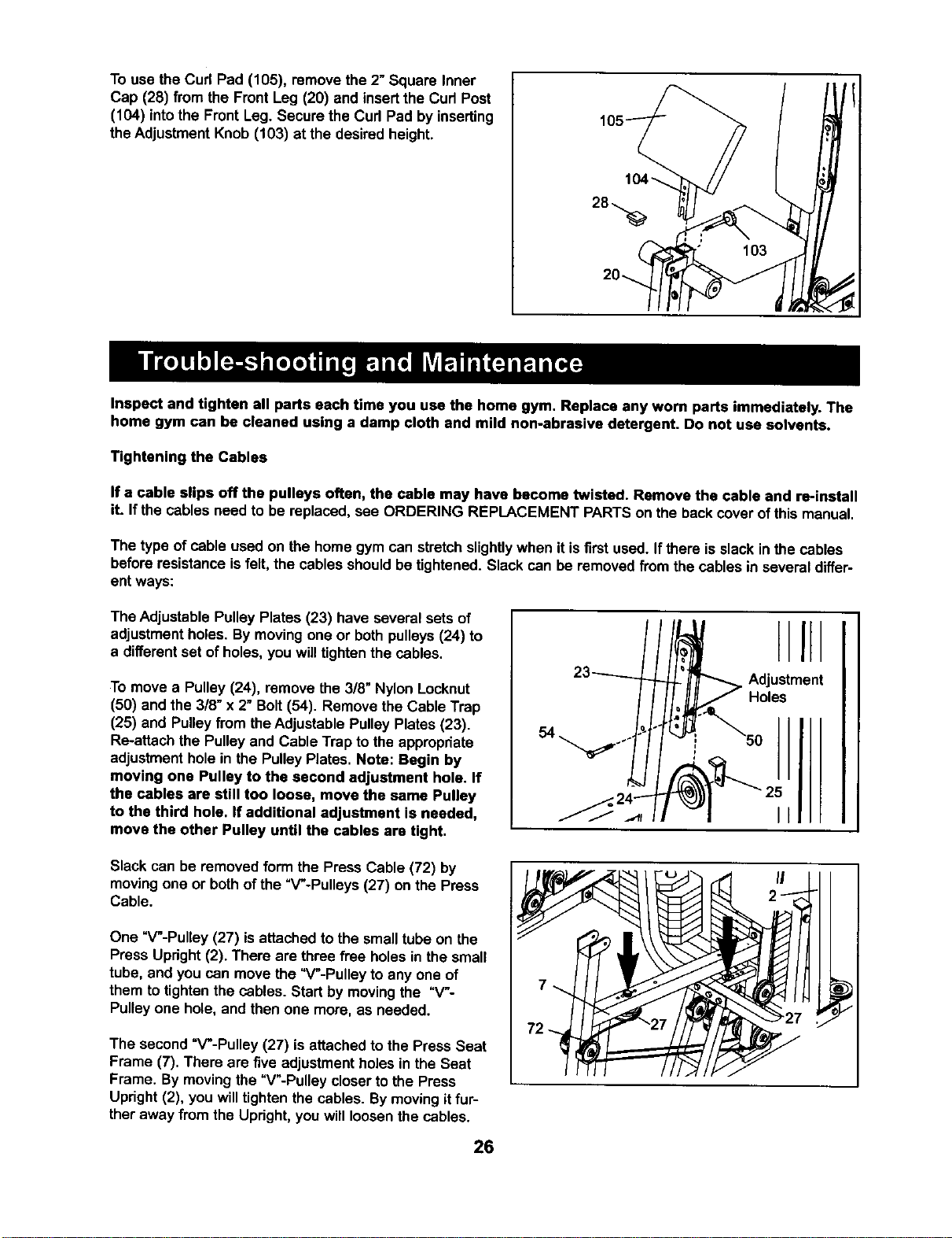
To use the Cud Pad (105), remove the 2" Square Inner
Cap (28) from the Front Leg (20) and insertthe Cud Post
(104) intothe Front Leg. Secure the Cud Pad by inserting
the AdjustmentKnob (103) at the desired height.
Inspect and tighten all parts each time you use the home gym, Replace any worn parts immediately. The
home gym can be cleaned using a damp cloth and mild non-abrasive detergent. Do not use solvents.
Tightening the Cables
If a cable slips off the pulleys often, the cable may have become twisted. Remove the cable and re-install
it. Ifthe cables need to be replaced,see ORDERING REPLACEMENT PARTSon the backcover of this manual.
The type of cable used on the home gym can stretchslightlywhen itis first used. If there isslack in the cables
before resistanceisfelt, the cables shouldbe tightened. Slack can be removedfrom the cables in several differ-
ent ways:
The Adjustable Pulley Plates (23) have several sets of
adjustmentholes. By movingone or bothpulleys(24) to
a differentset ofholes, you will tightenthe cables.
To move a Pulley (24), remove the 3/8" Nylon Locknut
(50) and the 318"x 2" Bolt(54). Remove the Cable Trap
(25) and Pulleyfrom theAdjustable PulleyPlates (23).
Re-attach the Pulleyand Cable Trap to the appropdate
adjustmenthole in the PulleyPlates. Note: Begin by
moving one Pulley to the second adjustment hole. If
the cables are still too loose, move the same Pulley
to the third hole. If additional adjustment is needed,
move the other Pulley until the cables are tight.
I
Adjustment
Holes
II
Slack can be removed form the Press Cable (72) by
movingone or bothof the "V'-Pulleys (27) on the Press
Cable.
One "V'-Pulley (27) isattached to the smalltube on the
Press Upright(2). There are three free holes in the small
tube, and you can movethe "V'-Pulley to any one of
them to tightenthe cables. Start by movingthe =V-
Pulleyone hole, and then one more, as needed.
The second =V'-Pulley (27) is attached to the Press Seat
Frame (7). There are five adjustment holesin the Seat
Frame. By movingthe =V'-Pulley closerto the Press
Upright (2), you willtightenthe cables. Bymoving itfur-
ther away from the Upright,you will loosenthe cables.
26
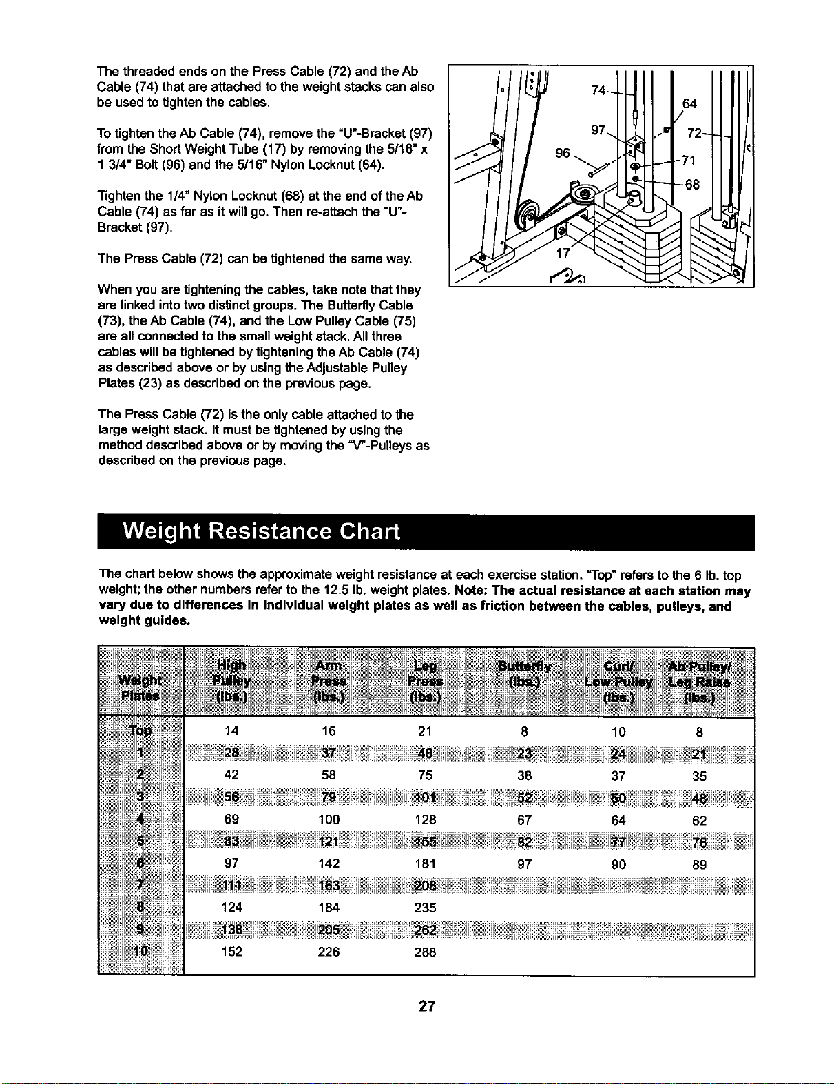
The threaded ends on the Press Cable (72) and theAb
Cable (74) that are attached to the weightstacks can also
be used to tightenthe cables.
To tightenthe Ab Cable (74), remove the =U"-Bracket (97)
from the ShortWeight Tube (17) by removingthe 5/16" x
1 3/4" Bolt(96) and the 5/16" Nylon Locknut(64).
Tightenthe 1/4" Nylon Locknut(68) at the end ofthe Ab
Cable (74) as far as it will go. Then re-attach the =U"-
Bracket (97).
The Press Cable (72) can be tightenedthe same way.
When you are tighteningthe cables, take notethat they
are linked intotwo distinctgroups. The ButterflyCable
(73), theAb Cable (74), and the Low PulleyCable (75)
are all connectedto the small weight stack.All three
cables willbe tightenedbytighteningthe Ab Cable (74)
as describedabove or by using theAdjustable Pulley
Plates (23) as describedon the previouspage.
The Press Cable (72) isthe onlycable attached tothe
large weight stack. It mustbe tightenedby usingthe
methoddescribed above or by movingthe "V"-Pulleys as
describedon the previouspage.
The chart belowshows the approximateweight resistanceat each exercise station."Top" referstothe 6 lb.top
weight;the other numbers refer to the 12.5 lb.weight plates. Note: The actual resistance at each station may
vary due to differences in individual weight plates as well as friction between the cables, pulleys, and
weight guides.
152 226 288
27
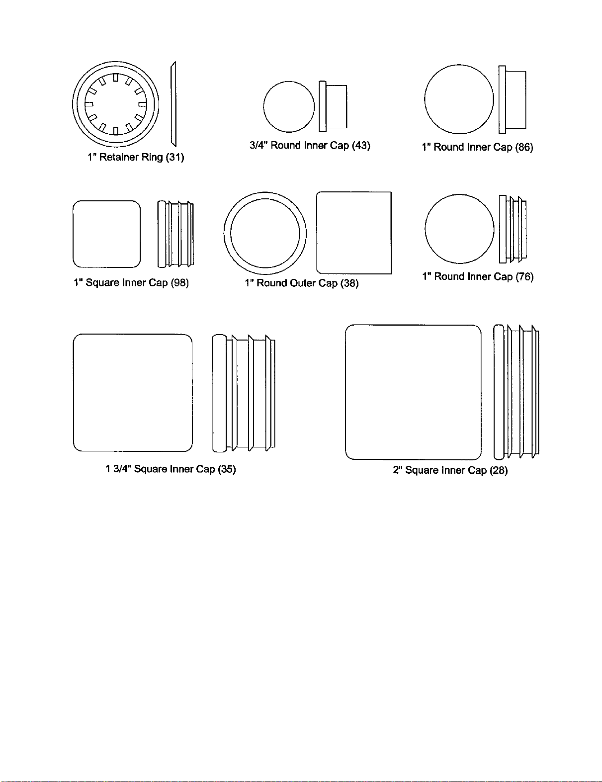
1"RetainerRing(31)
3/4" Round Inner Cap (43)
1" Round Inner Cap (86)
1" Square Inner Cap (98)
1" Round Outer Cap (38)
1" Round Inner Cap (76)
m
m
1 3/4" Square Inner Cap (35)
2" Square Inner Cap (28)
@8 @8
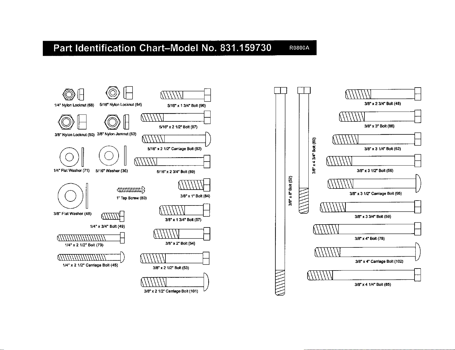
114" Nylon Locknut(68) 5/16" Nylon Locknut (64)
3/8" NylonLocknut (50) 3/8" Nylo_ Jamnut (63)
1/4" Flat Washer (71) 5/16" Washer (36)
©D
3/8" Flat Washer (48)
1"Tap Screw (80)
t/4" x 3/4" Bolt (49)
_\\\\\\\\\\\\\_\_ n
1/4" x 2 112"Bolt (79)
114"x 2 1/2" Carriage Bolt (45)
5/16" x 1 3/4" Bolt (96)
5/16" x 2 1/2" Bo8 (87)
_\\\\\\1 [)
5/16" x 2 112-Carriage Bolt(92)
6,\\\\\\1 E_
5/16" x 2 3/4" Bolt (89)
3/5" x 1" Bolt (84)
3/3" x I 3/4" Bolt (57)
B
3/8" x 2" Bolt (54)
3/8" x 2 1/2" So8 (53)
_\\\\\\\l
3/8_x 2 1/2" Carriage Bolt (t01)
7
J
J
J
J
J
J
g
=
_D
io
_,\\\\\\\1
3/8" x 2 3/4" Bolt (46)
_\\\\\\\1
3/8" x 3" Bolt (88)
_,\\\\\\\l
i _\\\\\\\1 3/_-,311.Bo_(8,)
3/8" x 3 1/2" Bolt (56)
_\\\\\\\1
318"x 3 1/2- Carriage Bolt (95)
_\\\\\\\1
3/8" x 3 3/4" 8o8 (59)
_\\\\\\\l
3/8" x 4" Bo8 (78)
_\\\\\\\l
3/8" x 4" Carriage Bolt (1021
_\\\\\\/
3/8" x 4 1/4" Bolt (85)
D
B
B
D
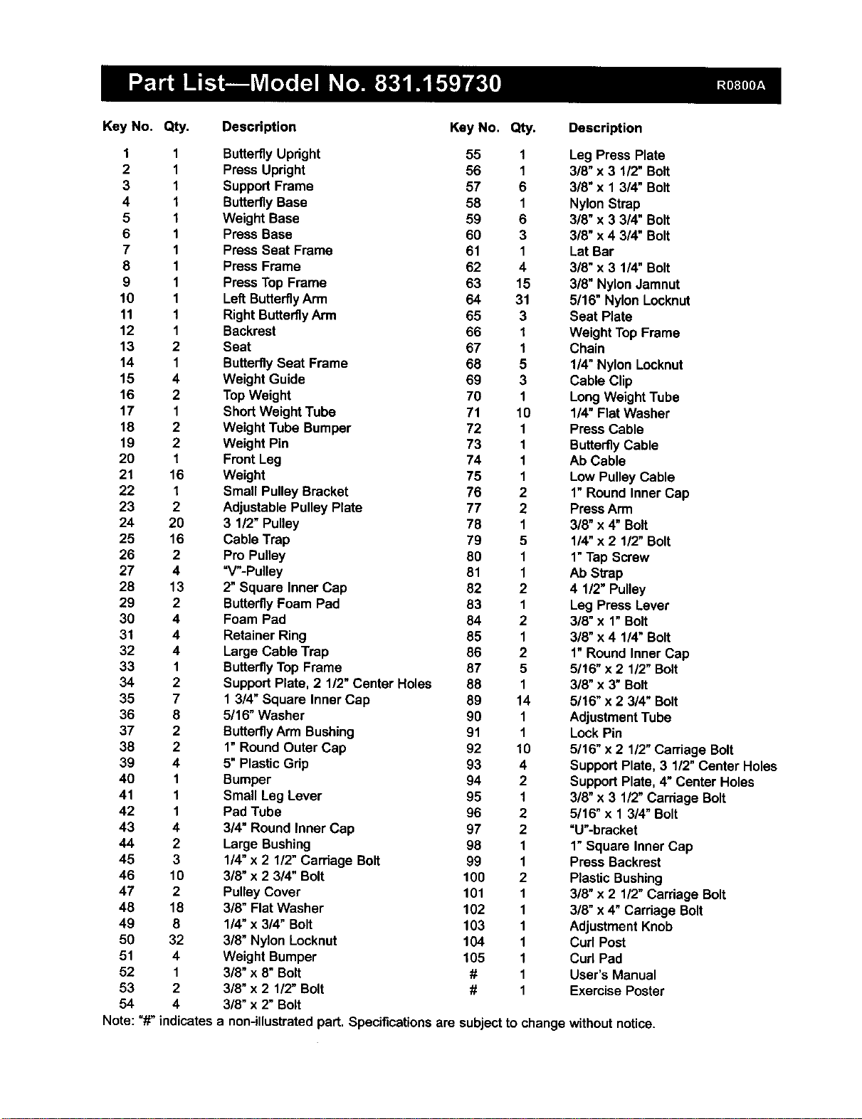
Key No. Qty. Descdptlon
Key No. Qty. Description
1 1 ButterflyUpright 55 1
2 1 Press Upright 56 1
3 1 Support Frame 57 6
4 I ButterflyBase 58 1
5 I Weight Base 59 6
6 1 Press Base 60 3
7 1 Press Seat Frame 61 1
8 1 Press Frame 62 4
9 1 PressTop Frame 63 15
10 1 Left ButterflyArm 64 31
11 1 Right Butterfly Arm 65 3
12 1 Backrest 66 I
13 2 Seat 67 1
14 1 ButterflySeat Frame 68 5
15 4 Weight Guide 69 3
16 2 TopWeight 70 1
17 1 Short Weight Tube 71 10
18 2 Weight Tube Bumper 72 1
19 2 Weight Pin 73 1
20 1 Front Leg 74 1
21 16 Weight 75 1
22 I Small Pulley Bracket 76 2
23 2 Adjustable Pulley Plate 77 2
24 20 3 1/2" Pulley 78 1
25 16 Cable Trap 79 5
26 2 Pro Pulley 80 1
27 4 "V"-Pulley 81 1
28 13 2" Square Inner Cap 82 2
29 2 ButterflyFoam Pad 83 1
30 4 Foam Pad 84 2
31 4 Retainer Ring 85 1
32 4 Large Cable Trap 86 2
33 1 ButterflyTop Frame 87 5
34 2 SupportPlate, 2 1/2"Center Holes 88 1
35 7 1 3/4" Square Inner Cap 89 14
36 8 5/16" Washer 90 1
37 2 ButterflyArm Bushing 91 1
38 2 1"Round Outer Cap 92 10
39 4 5"Plastic Grip 93 4
40 1 Bumper 94 2
41 1 Small Leg Lever 95 1
42 1 Pad Tube 96 2
43 4 3/4" Round Inner Cap 97 2
44 2 Large Bushing 98 1
45 3 1/4"x 2 1/2" Carriage Bolt 99 1
46 10 3/8" x 2 3/4" Bolt 100 2
47 2 Pulley Cover 101 1
48 18 3/8" Flat Washer 102 1
49 8 1!4"x 3/4" Bolt 103 1
50 32 3/8" Nylon Locknut 104 1
51 4 Weight Bumper 105 1
52 1 3/8" x 8" Bolt # 1
53 2 3/8" x 2 1/2"Bolt # 1
54 4 3/8" x 2" Bolt
Note: "#" indicates a non-illustrated part. Specificationsare subjectto
Leg Press Plate
3/8" x 3 112"Bolt
3/8"x 1 3/4" Bolt
Nylon Strap
3/8" x 3 3/4" Bolt
3/8" x 4 3/4" Bolt
Lat Bar
3/8" x 3 1/4" Bolt
3/8" Nylon Jamnut
5/16" Nylon Locknut
Seat Plate
Weight TopFrame
Chain
1/4" Nylon Locknut
Cable Clip
LongWeight Tube
114"Flat Washer
Press Cable
ButterflyCable
Ab Cable
Low Pulley Cable
1"Round Inner Cap
PressArm
318"x 4" Bolt
1/4" x 2 1/2" Bolt
1"Tap Screw
Ab Strap
4 1/2" Pulley
Leg Press Lever
3/8" x 1" Bolt
3/8" x 4 1/4" Bolt
1"Round Inner Cap
5116"x 2 112"Bolt
3/8" x 3" Bolt
5/16" x 2 3/4" Bolt
AdjustmentTube
Lock Pin
5/16" x 2 112"Carriage Bolt
Support Plate, 3 1/2" Center Holes
SupportPlate, 4"Center Holes
3/8" x 3 1/2"Carriage Bolt
5/16" x 1 3/4" Bolt
"U'-bracket
1"Square Inner Cap
Press Backrest
Plastic Bushing
3/8" x 2 112"Carriage Bolt
3/8"x 4" Carriage Bolt
AdjustmentKnob
Curl Post
Cud Pad
User's Manual
Exercise Poster
changewithout notice.
63
63
43
84
38
28
3O
28
/10
103 :
75
28
28
64
50
59
92 57
45
50
2\
58
59 5o
91 24_ _-57 24
55
64
24
44
101 102
92
J
60
64
48_; 48 77
SEARS
Model No. 831.159730
QUESTIONS?
If you find that:
• you need help assembling or
operating the WELDER" PRO 9940
Home Gym
• a part is missing
• or you need to schedule repair
service
call our toll-free HELPLINE
1-800-736-6879
Monday-Saturday, 7 arn-7 pm
Central Time (excluding holidays)
REPLACEMENT
PARTS
If parts become wom and need to
be replaced, call the following toll-
free number
1-800-FON-PART
(1-800-366-7278)
The modelnumber and serialnumber of yourWELDER"PRO
9940 Home Gym are listedon a decal attachedto the frame. See
the frontcover ofthis manual to findthe locationof the decal.
All replacement partsare available for immediatepurchase or
specialorder when you visityour nearest SEARS Service Center.
To requestservice or to order parts by telephone, callthe toll-free
numbers listedat the left.
When requestinghelpor service,or orderingparts,please be pre-
pared to providethe followinginformation:
• The MODEL NUMBER of the product (831.159730)
• The NAME of the product(WELDER" PRO 9940 Home Gym)
• The KEY NUMBER and DESCRIPTION ofthe PART (see the
PART LIST/EXPLODED DRAWING inthe center ofthis manual).
SEARS, ROEBUCK AND CO., HOFFMAN ESTATES, IL 60179
[ FULL 90 DAY WARRANTY I
For 90 days from the date of purchase,iffailure occursdue todefect in materialor workmanshipinthis
SEARS WEIGHT SYSTEM EXERCISER, contactthe nearest SEARS Service Center throughoutthe
United States and SEARS will repair or replace the WEIGHT SYSTEM EXERCISER, free ofcharge.
This warranty does not apply when the WEIGHT SYSTEM EXERCISER is used commerciallyor for
rentalpurposes.
This warrantygives you specificlegalrights,and you may also have other rightswhich varyfrom state
to state.
SEARS, ROEBUCKAND CO., DEPT. 817WA, HOFFMAN ESTATES, IL 60179
Part No. 158051 R0800A Printed in Canada © 1999 Sears, Roebuck and Co.