
www.vents-us.com
User’s
manual
Manuel
d'utilisation
Manual
de usuario
ES
EN
FR
Wall-Through Ventilation Fan

2
READ CAREFULLY AND SAVE THESE INSTRUCTIONS.
EN
WARNING!
READ CAREFULLY AND SAVE THESE INSTRUCTIONS TO REDUCE THE RISK OF FIRE, ELECTRIC SHOCK AND
PERSONAL INJURY.
1. Use the product only in the manner intended by the manufacturer. If you have questions, contact the manufacturer.
2. Before servicing or cleaning the product, switch off the power at the main service panel and lock it to prevent the
power from accidentally being turned on. If the panel cannot be locked securely, fasten a prominent warning device,
such as tag, to it. If the fan is not hard-wired but rather plugged into a 120 Volt outlet, unplug the cord from the
receptacle.
3. Installation work and electrical wiring must be done by qualified person(s) in accordance with all applicable codes
and standards, including fire-rated construction codes and standards.
4. Sufficient air is needed for proper combustion and exhaust of gases through the flue (chimney) of fuel burning
equipment to prevent back drafting. Follow the heating equipment manufacturer's guidelines and safety standards such
as those published by the National Fire Protection Association (NFPA), and the American Society for Heating,
Refrigeration and Air Conditioning Engineers (ASHRAE), and the local code authorities.
5. When cutting or drilling into wall or ceiling, do not damage electrical wiring and other hidden utilities.
6. The exhaust fans must always be vented to outdoors.
7. The fan may have sharp edges. Use caution to avoid being cut when installing and cleaning.
8. The fan must be grounded.
CAUTION!
1. For general ventilation use only. Not for use in fire rated installations. Do not use the fan to exhaust hazardous or
explosive materials and vapors.
2. For interior use only. Mount with the lowest moving parts at least 8 feet (2.5 meters) above the floor or grade level.
3. To avoid the motor damage and noisy and/or unbalanced impeller, keep drywall spray, construction dust, etc. off the
power unit.
4. Prior to installation operations make sure there is no visible damage to the impeller and housing.
Also make sure there are no foreign objects in the fan.
5. Please read specification label on product for further information and requirements.
6. Both the inlet and outlet must have no obstructions for the fan to work properly and be covered by the warranty.
7. When storing the fan keep it in a dry, weather-protected environment in the original packaging. If the fan has been
stored or set in a cold environment, wait 2 hours before connecting it to the power source.

GENERAL
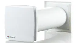
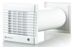
The product described herein is a ventilation for small up to medium-sized domestic premises. The fan and the ventilation fan
grille are made of plastic. The ventilation is designed for through-the-wall mounting, Fig. 1. fan
DELIVERY SET
Box includes:
1. Fan - 1
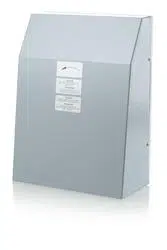
2. External grille - 1
3. Plastic air duct - 1
4. Screws and anchors - 6
5. User's manual
UNDERSTANDING MODEL NUMBER
The three digit number in all model names indicates the following:
100 (100 mm) means it is used with 4” air duct
125 (125 mm) means it is used with 5” air duct
150 (150 mm) means it is used with 6” air duct
MOUNTING
The ventilation is designed for through-the-wall mounting. fan
Mounting steps:
1. Select an installation place for the ventilation kit and drill a round core hole. Its diameter must match the air duct
diameter, Fig. 2.
2. Insert the air duct in the hole and fix it with a mounting foam, Fig. 3.
3. Install the fan, Fig. . 4-15
4. Install the external grille, Fig. . 16-19
Input: 120 VAC 60 Hz. The fan is equipped with a power cable with a plug for connection to a standard wall socket or with a
terminal box for direct connection to power supply. Connection to power supply is shown in Fig. . 20-23
OPERATION CONDITIONS
The ventilation kit is rated for continuous operation .
IPX4 rating ensures protection from splash of water for at least 5 minutes.
The fans can be operated at ambient temperatures between +32 F (0 °C) up to 113 F (+45 °C). +
MAINTENANCE
The fan surfaces need to be cleaned of dirt and dust regularly by using a soft, wet cloth and mild detergent.
Do not allow liquids to come in contact with the electric motor!
Wipe the surfaces dry after cleaning.
The product design is constantly being improved, that is why some models can differ slightly from those described in this
manual models.
3

WARRANTY
The product meets standard operating requirements in the North America.
VENTS US warrants to the original purchaser of the product that it will be free from defects in materials or workmanship for a
period of 24 months from the date of original purchase.
THERE ARE NO OTHER WARRANTIES, EXPRESS OR IMPLIED, INCLUDING, BUT NOT LIMITED TO, IMPLIED
WARRANTIES OF MERCHANTABILITY OR FITNESS FOR A PARTICULAR PURPOSE.
During the stated warranty period, VENTS US will, at its option, repair or replace, without charge, any product or part which is
found to be defective under normal use and service. This warranty does not cover (a) normal maintenance and normal service
or (b) any products or parts which have been subject to misuse, negligence, accident, improper maintenance or repair
(other than by VENTS US), faulty installation or installation contrary to recommended installation instructions.
Labor to remove and replace products is not covered.
The duration of any implied warranty is limited to the time period specified for the express warranty.
Some states do not allow limitations on how long an implied warranty lasts, so the above limitation may not apply to you.
VENTS US OBLIGATION TO REPAIR OR REPLACE, AT VENTS US OPTION, SHALL BE THE PURCHASER'S SOLE AND
EXCLUSIVE REMEDY UNDER THIS WARRANTY.
VENTS US SHALL NOT BE LIABLE FOR INCIDENTAL, CONSEQUENTIAL OR SPECIAL DAMAGES ARISING OUT OF OR IN
CONNECTION WITH PRODUCT USE OR PERFORMANCE.
Some states do not allow the exclusion or limitations of incidental or consequential damages, so the above limitation or exclusion
may not apply to you.
This warranty gives you specific legal rights, and you may also have other rights which vary from state to state.
This warranty supersedes all prior warranties.
If proof of sales date is not available, the warranty period is calculated from the production date.
The product can be exchanged at the following address:
Bodor Vents, LLC DBA: VENTS-US
11013 Kenwood Road Cincinnati, Ohio 45242
Phone: (513)348-3853
e-mail: [email protected]
Please follow guidelines in this manual for product problem-free operation.
4

LIRE ATTENTIVEMENT ET GARDER CETTE NOTICE
FR
ATTENTION!
LIRE ATTENTIVEMENT CETTE NOTICE AFIN D'EVITER L'INCENDIE, DECHARGE ELECTRIQUE ET SINISTRES
CORPORESLS
1. N'utilisez le produit que par sa vocation, précisée par le fabricant. Si vous avez des questions contactez le fabricant.
2. Consigner l'énergie électrique avant de passer à toute opération d'entretien ou de nettoyage. Bloquer le coffret
électrique afin d'éviter la mise en charge accidentelle. En cas d'impossibilité de bloquer le coffret électrique veuillez y
mettre un panneau de danger, par exemple une consigne. Si le produit est connecté à une prise de 120 V par le câble
à broche, tirer la broche de la prise pour déalimenter le produit.
3. Les travaux d'assemblage et de montage électrique ne doivent être exécutés que par des spécialistes qualifiés en
conformité de tous les normes et standards en vigueur y compris ceux de construction et d'antifeu.
4. Une quantité d'air suffisante est indispensable pour la combustion et l'échappement des gaz a travers le conduit
(cheminée) de l'équipement de combustion afin de prévenir le contre-tirage. Respecter le guide du fabricant pour
l'équipement de chauffage et les standards de sécurité tels que ceux publiés par l'Association Nationale de Protections
contre les Incendies (ANPI) et l'American Society for Heating, Refrigeration and Air Conditioning Engineers (ASHRAE),
aussi que des autorités du règlement local.
5. Lors de percement des orifices dans les murs ou dans le plafond pour monter le produit, tâchez, avec précaution,
de garder intacts la canalisation électrique et d'autres gaines cachées.
6. Les gaines des ventilateurs du tirage doivent être toujours mises en dehors du local.
7. Le produit peut présenter des coins vifs. Exécuter avec pécaution les travaux de montage et d'entretien pour éviter
des coupures.
8. Le produit doit être mis à la terre.
ATTENTION!
1. Le produit est destiné seulement à la ventilation générale et ne peut pas être exploité dans l'environnement agressif
ou avec le risque d'incendie. N'utilisez pas le produit pour l'aspiration des substances ou vapeurs explosives ou
dangereuses.
2. Pour l'usage intérieur seulement. La distance entre le niveau inférieur des pièces de rotation et le niveau du sol doit
être au moins 8 pieds (2,5 m).
3. Pour éviter des dommages du moteur, bruit ou déséquilibrage du rotor, protégez le bloc d'alimentation de la penture
dispersée, poussière de construction etc.
4. Avant de monter le produit, vérifiez que le rotor ou la boîte n'est pas endommagé. Vérifiez qu'il n'y a pas d'objets
étrangers dans la boîte.
5. Veuillez lire l'étiquette du fabricant pour plus d'informations et exigences.
6. Laissez les orifices d'admission et de sortie libres pour assurer le bon fonctionnement du produit et le recouvrement
par garantie.
7. Conservez le produit dans un endroit sec, protégé des agents atmosphériques dans l'emballage d'origine.
Si le ventilateur était conservé aux températures négatives veuillez attendre 2 heures avant de le brancher.
5

INFORMATION GENERALE
Le produit constitue le kit de ventilation pour les petits et moyens locaux sociaux.
Le produit et la grille sont fabriqués en matière plastique. Le produit est étudié pour l'encaster dans les mures. (fig. 1).
LOT DE LIVRAISON
Boîte d'emballage inclut:
1. Ventilateur - 1
2. Grille extérieure - 1
3. Gaine d'air en plastic - 1
4. Vis et chevilles - 6
5. Notice d'utilisateur
DESIGNATION
Interprtation du numéro du modèle. Le nombre de trois chiffres dans les noms de tous les modèles signifie ce qui suit :
100 (100 mm) signifie la compatibilité avec des gaines d'air de 4”
125 (125 mm) signifie la compatibilité avec des gaines d'air de 5”;
150 (150 mm) signifie la compatibilité avec des gaines d'air de 6”.
MONTAGE
Le kit de ventilation est destiné à monter encastré dans les murs.
Suite de montage :
1. Retenez l'endroit pour le montage et percez l'orifice rond de bout en bout au diamètre, correspondant à celui de la gaine
d'air (fig. 2).
2. Introduisez la gaine d'air dans l'orifice et l'immobilisez avec de la mousse de montage (fig. 3).
3. Montez le ventilateur (fig. ). 4-15
4. Montez la grille extérieure (fig. ). 16-19
Tension d'entrée: 120 V AC 60 Hz.
Le ventilateur est équipé de câble d'alimentation et de fourche pour la connexion à la prise de courant standard ou au bornier,
pour connecter en direct au secteur.
Le raccordement à la source d'énergie est montré sur les fig. . 20-23
CONDITIONS D'UTILISATION
Le kit de ventilation est destiné à l'utilisation de longue durée.
Le niveau de protection d'accès aux parties dangereuses et de pénétration d'eau IPX4.
Le produit est destiné à utiliser aux températures ambiantes de +32 F (0 °C) à 113 F (+45 °C). +
MAINTENANCE
Dépoussiérez et décrassez régulièrement les surfaces du produit avec le chiffon humide, humecté de détergent.
Evitez la dispersion d'un liquide sur le moteur!
Après le nettoyage essuyez bien les surfaces.
La construction des produits est en amélioration permanente, c'est pourquoi les spécifications de certains modèles peuvent
légèrement différer de celles décrites dans la présente notice.
6

GARANTIE
Le produit est fabriqué conformément aux normes d'utilisation des Etats-Unis et du Canada.
VENTS US garantit à l'acheteur du produit l'inexistence des défauts des matériaux ou des défauts de fabrication durant 60 mois
à partir de la date de sa première acquisition.
D'AUTRES GARANTIES ORDINAIRES OU TACITES Y COMPRIS MAIS SANS RESTRICTIONS DES GARANTIES TACITES
DE L'ETAT COMMERCIAL ET DE BON ETAT DE FONCTIONNEMENT NE SONT PAS PREVUES.
Pendant la période indiquée de garantie VENTS US, à son gré, s'engage à réparer ou remplacer tout produit ou ses pièces en
cas de détection des défauts. La présente garantie ne couvre pas (a) l'entretien et l'exploitation soit (b) du produit ou d'une
pièce endommagé par la suite de l'exploitation à destination non prévue, négligence, accident, entretien ou réparation mal
exécuté (sauf les réparations exécutées par VENTS US), la mauvaise installation ou non respect des consignes de la notice
d'utilisation et de montage. La garantie ne couvre pas le désassemblage et le transport du produit.
La validité de toute garantie tacite est limitée de la validité de la présente garantie. Certains états ne reconnaissent pas de
limitations de validité de la garantie tacite, dans ce cas-là lesdites limitations ne s'appliquent pas à votre cas.
LES ENGAGEMENTS DE VENTS US DE REPARATION OU DE REMPLACEMENT D'UN PRODUIT DEFECTUEUX,
A SON GRE, FAIT LE SEUL REMBOURSEMENT EXCLUSIF A L'ACHETEUR. VENTS US N'EST PAS RESPONSABLE DES
DOMMAGES ACCIDENTELS, SEQUENTIELS OU SPECIFIQUES CAUSES OU RELATIFS A L'UTILISATION ET
L'EXPLOITATION DU PRODUIT.
Certains états ne reconnaissent pas d'exclusions ou de restrictions de la responsabilité pour les dommages accidentels ou
séquentiels, dans ce cas-là lesdites restrictions ou exceptions ne s'appliquent pas dans votre cas.
La présente garantie vous donne certaines droits juridiques, vous pouvez également avoir d'autres droits qui sont différents
dans les états différents. La présente garantie est de préférence par rapport à toute autre garantie.
A défaut du justificatif de la date de vente, la garantie sera comptée à partir de la date de production.
Vous pouvez remplacer le produit à l'adresse:
Bodor Vents, LLC DBA: VENTS-US
11013 Kenwood Road Cincinnati, Ohio 45242
Phone: (513)348-3853
e-mail: sales@ventsus.com
Suivre les consignes de la présente notice afin d'assurer le bon fonctionnement du produit.
7

LEER Y GUARDAR ESTE MANUAL
ES
¡ADVERTENCIA!
PARA REDUCIR EL RIESGO DE INDENDIO, CHOQUE ELECTRICO, U OTROS TIPOS DE DAÑO A LAS
PERSONAS, RESPETAR LAS SIGUIENTES RELGLAS.
1. Utilizar el producto solamente para el uso previsto especificado por el fabricante. En caso de cualquier pregunta,
dirigirse al fabricante.
2. Antes de poner en funcionamiento o limpieza del producto, apague la corriente en el panel principal de servicio y
bloquéelo para evitar un encendido accidental. Si no se puede bloquear el panel con seguridad, coloque de forma
destacada una advertencia, por ejemplo, una etiqueta, en panel. Si el producto está conectado en la toma de corriente
de 120 voltios, simplemente desenchufe el cable de la toma de corriente.
3. El trabajo de instalación y el cableado eléctrico deben realizarse por personal cualificado de acuerdo con todos los
códigos y estándares aplicables, incluyendo los códigos de clasificación anti-incendios y estándares de construcción.
4. Es necesaria una suficiente cantidad de aire para una combustión correcta y una extracción de gases de escape
a través de un tiro (salida de humo), y para prevenir la retroalimentación con gases de escape.
Seguir las instrucciones del fabricante de la maquinaria de calefacción y las normas de seguridad elaboradas por la
Asociación Nacional de la Defensa contra Indendios (NPFA), la Sociedad Americana de Ingenieros de maquinaria para
calefacción, refrigeración y acondicionamiento de aire (ASHRAE) y las autoridades locales.
5. Al abrir un agujero en la pared o realizar otra obra de construcción, no dañar los cables elécricos del producto.
6. El tubo de escape siempre deber salir hacia fuera.
7. Este producto puede tener filos agudos. Al instalarlo, cuidar de tomar las precauciones de seguridad debidas para
no lastimarse.
8. Este producto debe tener toma de tierra.
¡PRECUACIÓN!
1. Usar solamente para una ventilación general. No debe utilizarse en ambientes agresivos o con peligros de incendio.
No usar el producto para extracción de materiales peligrosos o explosivos y vapores.
2. Solamente para uso interior. La distancia mínima entre las partes móviles hasta el suelo o nivel de tierra será al
menos de 8 pies (2,5 metros ).
3. Para evitar el daño del motor y el impulsor ruidoso y/o desequilibrado, no permita rociado de pintura, polvo de
construcción, etc. en el producto.
4. Antes de la operación de instalación asegúrese de que no hay daños visibles en el impulsor y la carcasa.
También asegúrese de que no haya objetos extraños que puedan haberse introducido accidentalmente en el producto.
5. Por favor lea la etiqueta de especificaciones del producto para más información y requisitos.
6. Tanto la entrada y la salida no deben tener obstáculos para el producto pueda funcionar correctamente y estar
cubierto por la garantía.
7. Cuando guarde el producto guárdelo en un lugar seco y protegido de la intemperie en el embalaje original.
Si el producto haya sido almacenado o situado en un ambiente frío, espere 2 horas antes de conectarlo a la fuente
de alimentación.
8

INFORMACIÓN GENERAL
El producto es un juego de ventilación para los pequeños y medianos locales domésticos.
El producto y la rejilla están fabricados de plástico. El producto está diseñado para montaje interior (Fig. 1).
JUEGO DE SUMINISTRO
La caja incluye:
1. Ventilador - 1
2. Rejilla exterior- 1
3. Conducto plástico de aire - 1
4. Tornillos y tarugos - 6
5. Manual de usuario
EXPLICACIÓN DE LOS NÚMEROS DE MODELO
El número de tres dígitos en todos los nombres de modelo indica lo siguiente:
100 (100 mm) significa la compatibilidad con conductos de aire de 4”;
125 (125 mm) significa la compatibilidad con conductos de aire de 5”;
150 (150 mm) significa la compatibilidad con conductos de aire de 6”.
MONTAJE
El juego de ventilación es destinado para el montaje en la pared.
El orden de montaje:
1. Elegir el lugar para montar el producto y perforar un agujero pasante circular con un diámetro que corresponde al diámetro
del conducto de aire (Fig. 2).
2. Instalar el conducto de aire en el agujero y fijarlo con espuma (Fig. 3).
3. Instalar el producto (Fig. ). 4-15
4. Instalar la rejilla exterior (Fig. ). 16-19
Entrada: 120 VCA 60 Hz.
El producto está equipado con un cable de alimentación y el enchufe para la conexión a una tomacorriente estándar o a una
caja de bornes para conectar a la red directamente.
Conexión a la fuente de alimentación se muestra en la figura . 20-23
CONDICIONES DE FUNCIONAMIENTO
El juego de ventilación es destinado para un funcionamiento continuo.
El grado de protección contra el acceso a las partes peligrosas y la penetración de agua es: IPX4.
El producto está diseñado para funcionar a una temperatura ambiente de +32 °F (0 °C) a 113 °F (+45 °C). +
MANTENIMIENTO TÉCNICO
Es necesario limpiar regularmente las superficies del prodecto de la suciedad y del polvo con un paño suave y húmedo y un
detergente suave. No permita que los líquidos entren en contacto con el motor eléctrico.
Limpie las superficies hasta dejarlas secas después de la limpieza.
La construcción del producto se mejora constantemente y por eso algunos modelos pueden variar ligeramente de los
descritos en los manuales de usuario.
9

GARANTÍA
El producto cumple con requerimientos de explotación estándar vigentes en USA y Canada.
VENTS US garantiza al comprador del producto contra defectos de materiales o de fabricación dentro de los 60 meses desde
la fecha de compra original.
NO EXISTEN OTRAS GARANTÍAS, EXPRESAS O IMPLÍCITAS, INCLUYENDO, PERO NO LIMITANDO LAS GARANTÍAS
IMPLÍCITAS DE COMERCIALIZACIÓN O IDONEIDAD PARA UN PROPÓSITO PARTICULAR.
Durante el período de garantía , VENTS US, a su elección, reparará o reemplazará, sin costo alguno cualquier producto o pieza
que se encuentre defectuosa bajo uso y servicio normal. Esta garantía no cubre (a) mantenimiento y servicio normales o (b)
cualquier producto o piezas que hayan sido objeto de mal uso, negligencia, accidente, mantenimiento o reparación inadecuada
(no hecha por VENTS US), instalación defectuosa, o instalación contraria a la instalación recomendada.
La labor de recoger y reponer los productos no está cubierta. La duración de cualquier garantía implícita se limita al período
de tiempo especificado en la garantía expresada. Algunos estados no permiten limitaciones en la duración de una garantía
implícita, por lo que la limitación anterior puede que no se aplique a Vd.
OBLIGACIONES DE VENTS US A REPARAR O REEMPLAZAR, A ELECCIÓN DE VENTS US, SERÁ EL ÚNICO Y
EXCLUSIVO REMEDIO AL COMPRADOR EN BASE A ESTA GARANTÍA. VENTS US NO SE HACE RESPONSABLE DE LOS
DAÑOS INDIRECTOS, ESPECIALES O DERIVADOS DE O EN CONEXIÓN AL USO O RENDIMIENTO DEL PRODUCTO.
Algunos estados no permiten la exclusión o limitación de daños incidentales o consecuentes, por lo que la limitación o
exclusión indicada arriba puede que no se aplique a Vd. Esta garantía le otorga derechos legales específicos y usted también
puede tener otros derechos que varían de estado a estado. Esta garantía reemplaza todas las garantías anteriores.
Si la prueba de la fecha de ventas es ausente, el período de garantía se calculará desde la fecha de fabricación.
Se puede reemplazar el producto a la siguiente dirección:
Bodor Vents, LLC DBA: VENTS-US
11013 Kenwood Road Cincinnati, Ohio 45242
Phone: (513)348-3853
e-mail: sales@ventsus.com
Por favor, sigan las indicaciones de este manual para un funcionamiento sin problemas del producto.
10
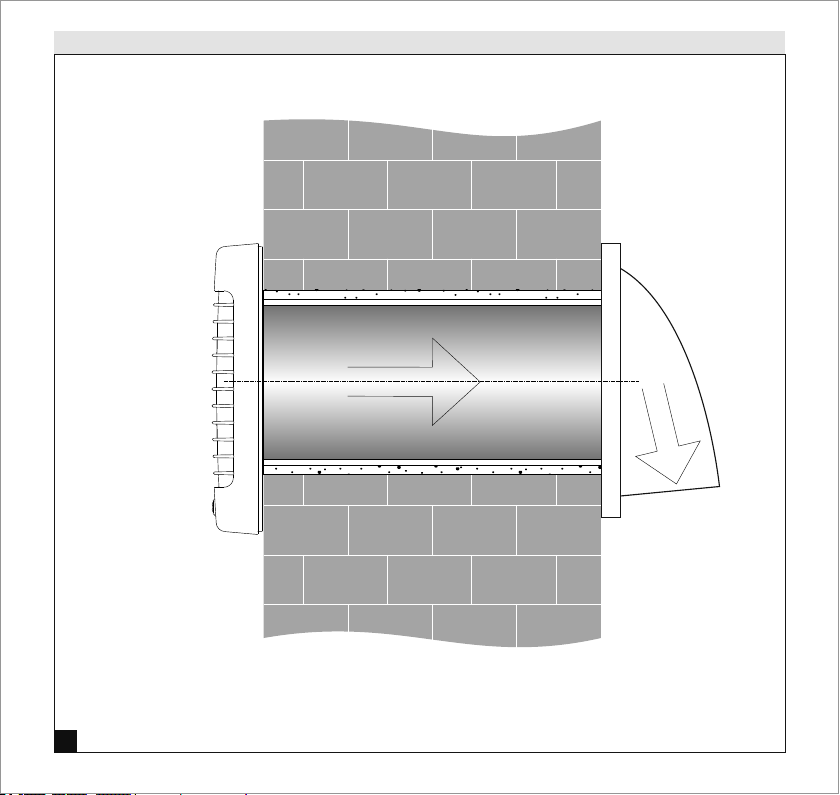
Typical installation
1
11
Outer
wall
Inner
wall

Air duct installation
2
min 3°
3
12
Outer wall
Inner wall
Install the air duct with the minimum slope 3°
downwards to ensure condensate drainage. Fill the
gap between the air duct and the wall with
mounting foam.
Prepare a round hole in the exterior wall of the
building. The hole size and the minimum
recommended distance to a mounting surface,
for example, a wall, ceiling or a window are
shown in the Figure.
min 20"
min 20"
min 20"
100 Kit - DIA (5")
125 Kit - DIA (6")
150 Kit - DIA (7")
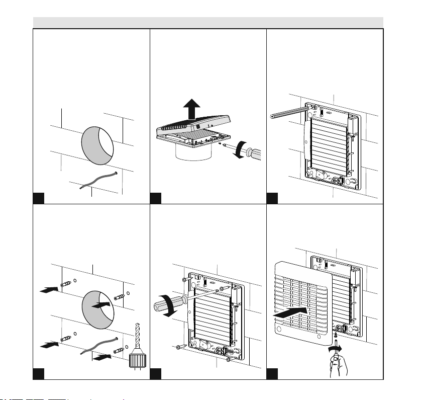
Installation of MA series wall-through ventilation fan
7
4
8
5
13
9
6
Use the back part of the front
panel to mark the four screw
holes. Drill the holes.
Remove the front panel cover to
enable access to the fastening
holes.
Connect the front panel cover with
the back part and secure them with
a screw at the bottom.
Route all the required cables.
If the fan is equipped with a
power cable and a plug, make
sure an electric outlet is located
no more than 9 ft from the fan.
Insert the expansion anchors in
the holes.
Fix the back part of the front
panel to the wall using the
supplied screws. Wire the fan
according to the wiring diagram in
Fig. 20 or 22.
13
10
14
11
15
12
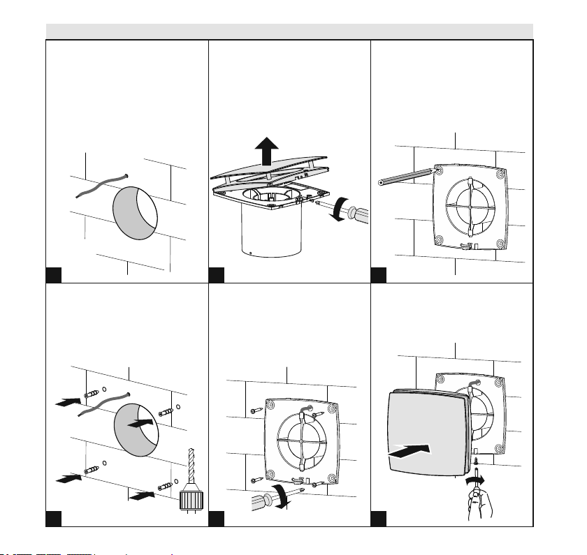
Installation of series wall-through ventilation fanLD
14
Use the back part of the front
panel to mark the 4 screw
holes.Drill the holes.
Remove the front panel cover to
enable access to the fastening
holes.
Connect the front panel cover with
the back part and secure them
with a screw at the bottom.
Route all the required cables.
If the fan is equipped with a
power cable and a plug, make
sure an electric outlet is located
no more than 9 ft from the fan.
Insert the expansion anchors in
the holes.
Fix the back part of the front
panel to the wall using the
supplied screws. Wire the fan
according to the wiring diagram in
Fig. 21 or 23.

Installation of outer hood
15
Disassemble the ventilation hood to ensure access to
the fastening holes. Disconnect and remove the front
part of the ventilation hood.
Insert the expansion anchors in the holes
Fix the back part of the ventilation hood to the wall
using the supplied screws. Secure the hood to the
back plate by pressing the two parts together.
Easy click installation
Use the back part of the hood to mark the four
screw holes. Drill the holes.
18
16
19
17

120VAC, 60Hz
POWER SOURCE
QF
AUTOMATIC
SWITCH
GREEN
GROUND
SCREW
HOUSE JUNCTION BOX
EARTH
GROUND
FAN
Electrical Connection of MA series wall-through ventilation fan
STANDARD
WALL SOCKET
20
16

FAN
Electrical Connection of LD series wall-through ventilation fan
21
17
120VAC, 60Hz
POWER SOURCE
QF
AUTOMATIC
SWITCH
GREEN
GROUND
SCREW
HOUSE JUNCTION BOX
STANDARD
WALL SOCKET
EARTH
GROUND
S
JUNCTION
BOX
120VAC, 60Hz
POWER SOURCE
STANDARD
WALL SWITCH
QF
AUTOMATIC
SWITCH
GREEN
GROUND
WIRE
TO FAN
TO S
TO QF
AND
GROUND SCREW
GREEN
GROUND
SCREW
HOUSE JUNCTION BOX
GROUND
FAN
L
N
X
N
L
N
L
~120V 60Hz
X
QF
S
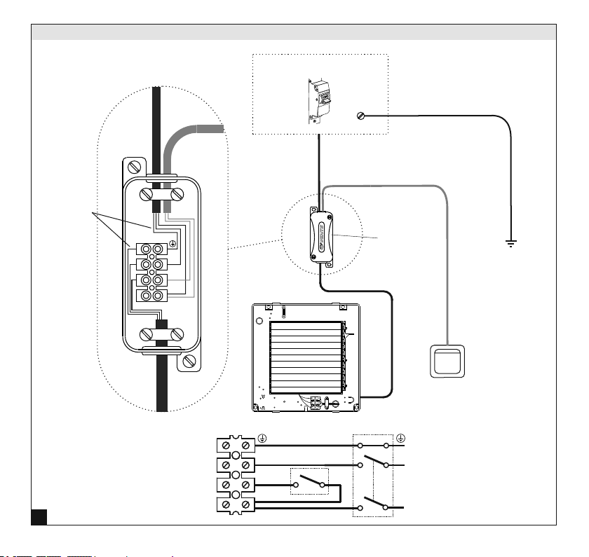
Electrical connection MA series standard wall switch
1g
22
18
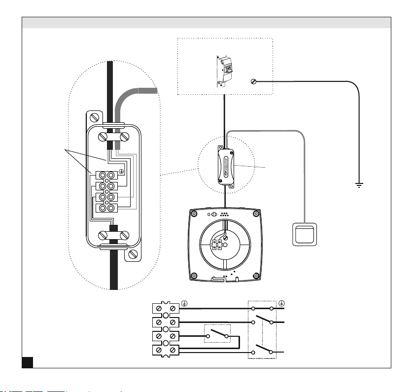
S
JUNCTION
BOX
120VAC, 60Hz
POWER SOURCE
STANDARD
WALL SWITCH
QF
AUTOMATIC
SWITCH
GREEN
GROUND
WIRE
TO FAN
TO S
TO QF
AND
GROUND SCREW
GREEN
GROUND
SCREW
HOUSE JUNCTION BOX
GROUND
FAN
L
N
X
N
L
N
L
~120V 60Hz
X
QF
S
Electrical connection LD series standard wall switch
1g
23
19

www.vents-us.com
100
125
150
LD Kit
MA Kit
ACCEPTANCE CERTIFICATE
CERTIFICAT D'ACCEPTATION
CERTIFICADO DE CALIDAD
Date of sale
Date de la vente
Fecha de venta
Manufactured on (date):
Vendu
(nom d'entreprise de commerce, cachet du magasin)
Fabriqué le (date)
Approval mark
Fecha de producion
Signe d'approbation
Marca de verificador
Vendido
(nombre de empresa, timbro o sello)
Sold
(name of trading enterprise, stamp of store)
The fan has been duly certified as serviceable.
Le ventilateur a été certifié comme utilisable.
Este ventilador está certificado para el uso normal.
V-US141EN-02