Loading ...
Loading ...
Loading ...
8. Recheck both support channels to make sure
that tightening screws did not affect the accuracy
of the adjustment.
9. Elevate saw and return motor to horizontal posi-
tion to provide clearance for installation of front
(work) table.
INSTALLATION OF FRONT (WORK)
TABLE
.
.
.
.
.
.
From loose parts bag #499, locate the following
hardware:
4- Pan Head Bolts 1/4-20 x 1
5- Flat Washers 17/64 x 5/8 x 1/32
4 - Lockwashers 1/4
4- Hex Nuts 1/4-20
From loose parts bag #529, locate the following
hardware:
1 - Tee Nut 1/4-20
1 - Cup Point Set Screw !/4-20 x 7/8
1 - U-Clip 1/4-20
1 - Pan Head Machine Screw 1/4-20 x 1-3/4
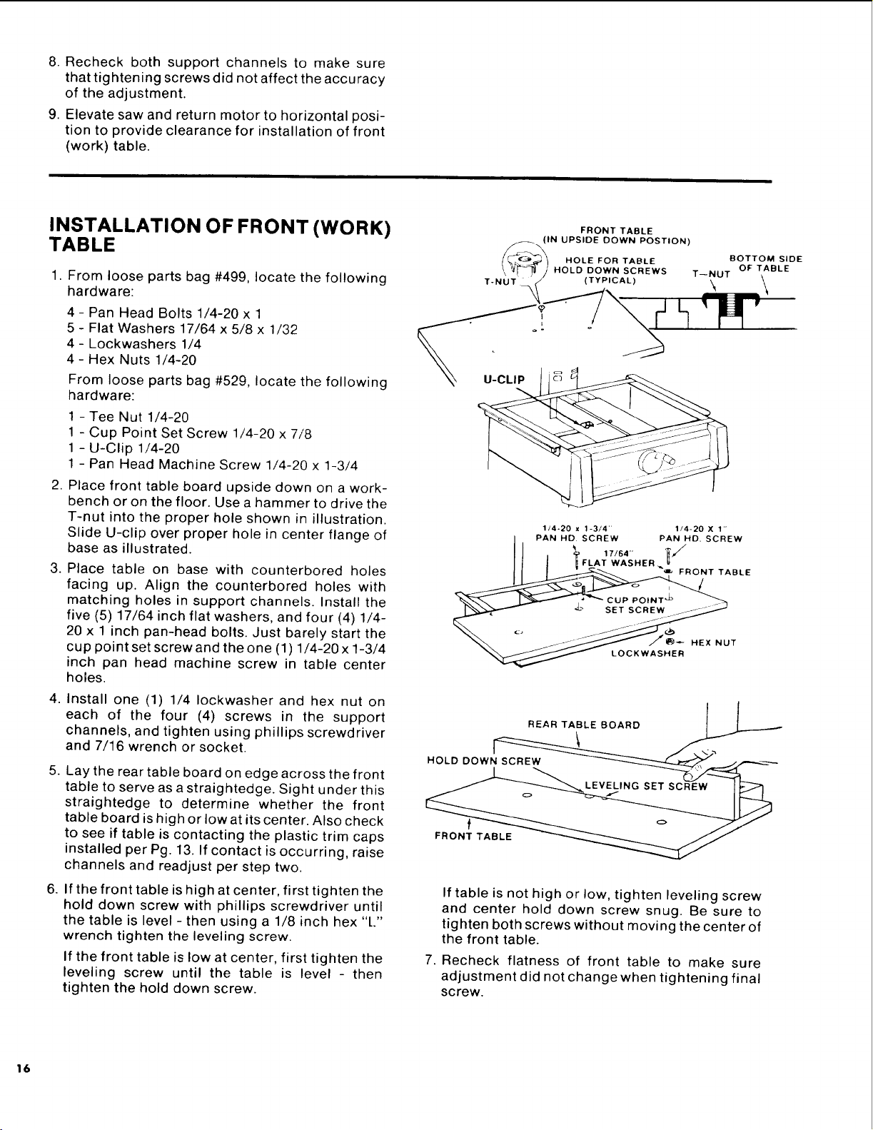
Place front table board upside down on a work-
bench or on the floor. Use a hammer to drive the
T-nut into the proper hole shown in illustration.
Slide U-clip over proper hole in center flange of
base as illustrated.
Place table on base with counterbored holes
facing up. Align the counterbored holes with
matching holes in support channels. Install the
five (5) 17/64 inch flat washers, and four (4) 1/4-
20 x 1 inch pan-head bolts. Just barely start the
cup point set screw and the one (1) 1/4-20 x 1-3/4
inch pan head machine screw in table center
holes.
Install one (1) 1/4 Iockwasher and hex nut on
each of the four (4) screws in the support
channels, and tighten using phillips screwdriver
and 7/16 wrench or socket.
Lay the rear table board on edge across the front
table to serve as a straightedge. Sight under this
straightedge to determine whether the front
table board is high or low at its center. Also check
to see if table is contacting the plastic trim caps
installed per Pg. 13. If contact is occurring, raise
channels and readjust per step two.
If the front table is high at center, first tighten the
hold down screw with phillips screwdriver until
the table is level - then using a 1/8 inch hex "L"
wrench tighten the leveling screw.
If the front table is low at center, first tighten the
leveling screw until the table is level - then
tighten the hold down screw.
FRONT TABLE
.. (IN UPSIDE DOWN POSTION)
HOLE FOR TABLE
/ _/[_J_ J HOLD DOWN SCREWS T--NUT
\ . /
T-NUT _ (TYPICAL) \
u-cuP
BOTTOM SIDE
OF TABLE
\
F
1/4o20 x 1-3/4" 1/4-20 X 1'"
PAN HD. SCREW PAN NO. SCREW
FLAT WASHER _ u
FRONT TABLE
_ HEX NUT
LOCKWASHER
HOLD DOW_
REAR TABLE BOARD '_:',
If table is not high or low, tighten leveling screw
and center hold down screw snug. Be sure to
tighten both screws without moving the center of
the front table.
7. Recheck flatness of front table to make sure
adjustment did not change when tightening final
screw.
16
Loading ...
Loading ...
Loading ...