Loading ...
Loading ...
Loading ...
9
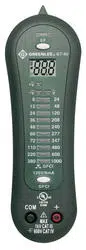
GT-65 • GT-95
Operation (cont’d)
Test Table
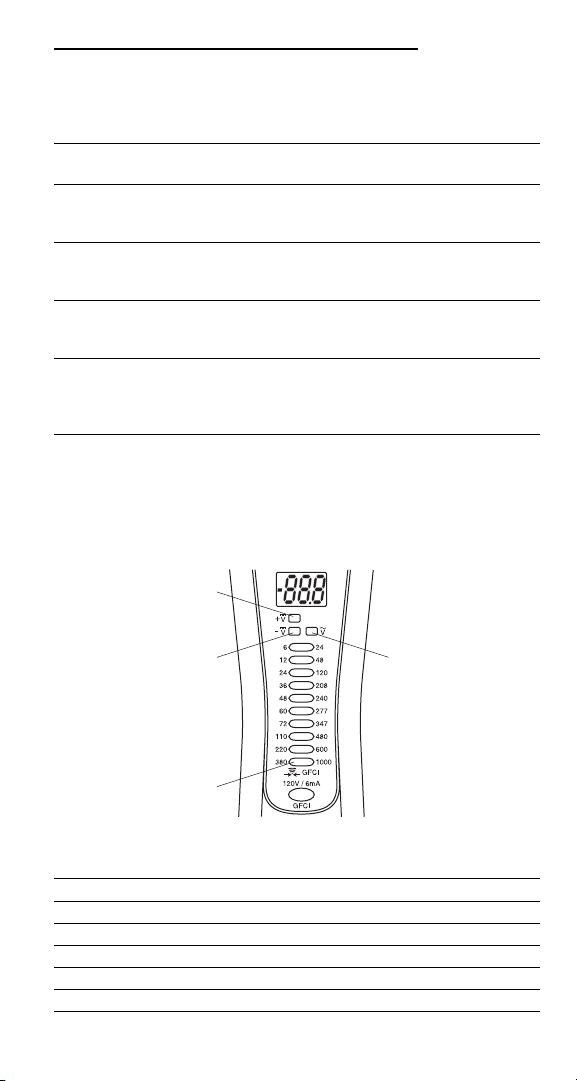
LED Table
LED Illuminated Indication
LED 1 Positive (+) DC of 4.5 V or more
LED 2 Negative (–) DC of 4.5 V or more
LED 3 AC of 15 V or more
LED 4 only Continuity present
Other voltage LEDs Approximate voltage level
LED 1
LED 2
LED 4
LED 3
To test/verify Connect the Connect the The tester
this value: red lead to: black lead to: will indicate:
Continuity Component Component Tone for resistance
or circuit or circuit of 0 to 50 kΩ
under test under test (approximately)
AC voltage Component Component Voltage of 15 V
or circuit or circuit or greater*
under test under test
DC voltage Component Component Voltage of 4.5 V
or circuit or circuit or greater,
under test under test plus polarity*
GFCI Hot or live Earth Refer to “Typical
(GT-95 only) conductor ground Measurements”
for complete
testing instructions.
*GT-95 also displays voltage on LCD.
Loading ...
Loading ...
Loading ...