Loading ...
Loading ...
Loading ...
4
E
General Information
4
E
14-1/4" (361.95 mm)
Minimum Cutout Opening Width 27-3/4" (704.9 mm)
Minimum Cutout Opening Height 16-9/16" (420.7 mm)
Maximum Cutout Opening Height 16-13/16" (427 mm)
Maximum Cutout Opening Width 28" (711.2 mm)
Distance between holes A9.1" (231.2 mm)
14" (355.6 mm)
Center Line
Floor Line of Cutout Opening
BUILT-IN TRIM KIT
SURFACE MOUNTING TEMPLATE
FOR DESIGNER SERIES MICROWAVE OVEN
TINSKB180MRR0
1/4"
(6.2 mm)
1/4"
(6.2 mm)
1. Align the Surface Mounting Template center line with the
center of the cabinet. Align the Floor Line with the bottom
of the cabinet at the desired height. Tape it into place.
2. Predrill 4 holes marked A with a ¹₁₆" drill bit.
3. Cut the cabinet opening between the minimum and
maximum cutout opening lines. Be careful to cut precisely
along the Floor Line of the cutout.
4. Remove template from the cabinet.
3-15/16" (100 mm)
7
2
1) Frame Assembly: QTY 1 2) Bottom Duct Assembly: QTY 1
3) Mouting Bracket: QTY 2 4) SIDE DECORATION: QTY 2
(SURFACE MOUNTING ONLY)
3
1) Frame Assembly: QTY 1 2) Bottom Duct Assembly: QTY 1
3) Mouting Bracket: QTY 2 4) SIDE DECORATION: QTY 2
(SURFACE MOUNTING ONLY)
6
1) Frame Assembly: QTY 1 2) Bottom Duct Assembly: QTY 1
3) Mouting Bracket: QTY 2 4) SIDE DECORATION: QTY 2
(SURFACE MOUNTING ONLY)
1
1) Frame Assembly: QTY 1 2) Bottom Duct Assembly: QTY 1
3) Mouting Bracket: QTY 2 4) SIDE DECORATION: QTY 2
(SURFACE MOUNTING ONLY)
4
5
4-3/16" (106.4 mm)
FLOOR LINE OF CUTOUT OPENING
BUILT-IN TRIM KIT
FLUSH MOUNTING TEMPLATE
FOR DESIGNER SERIES MICROWAVE OVEN
CABINET CUTOUT LINE
CABINET CUTOUT LINE
CENTER LINE
TINSKB181MRR0
1. Align the Flush Mounting Template center line with the center of the
cabinet. Align the Floor Line with the bottom of the cabinet at the
desired height. Tape it in place.
2. Cut the cabinet opening along the three Cabinet Cutout Lines and
the Floor Line.
3. Install two Side Spacers (see FIGURE 1) and one Bottom Spacer (see
FIGURE 2) as specified in FIGURE 3. Be sure to offset all three spacers
by 1⁹₁₆" from the front surface of the cabinet.
4. Cut out the Side Spacer Templates (R and L) and align the indicated
edge to the corresponding Side Spacer (see FIGURE 3). Be careful to
align the Floor Line to the bottom edges of the Side Spacers.
5. Predrill two holes indicated “A“ in Side Spacer - R with a ¹₁₆" drill bit.
6. Predrill two holes indicated ”B“ in Side Spacer - L with a ¹₁₆" drill bit.
7. Remove template from the cabinet.
SIDE SPACER TEMPLATE - L
SIDE SPACER TEMPLATE - R
FIGURE 1
Side Spacer (2 required)
Must protrude from edge of cabinet
cutout towards center as shown.
Align Side Spacer-L to this line
Align Side Spacer-R to this line
Cutout Opening Height 17-5/16" (439.8 mm)
CABINET CUTOUT LINE
Edges to align Side Spacer Templates (R and L)
Bottom Spacer centered with cabinet cutout
1-9/16" (39.7 mm)
Bottom and Side
Spacer (R and L) Offset
FIGURE 3
Side Spacer - L Side Spacer - R
14" (355.9 mm)
Distance between holes A9.1" (231.2 mm)
Cutout Opening Width 29-5/8" (752.5 mm)
14-13/16" (376.2 mm)
13/16" Min.
15/16 Max.
13-1/2" min. height
FIGURE 2
Bottom Spacer (1 required) ¹₄" plywood
24" min. width
27-7/8" max. width
1/4" (6.35 mm)1/4" (6.35 mm)
8
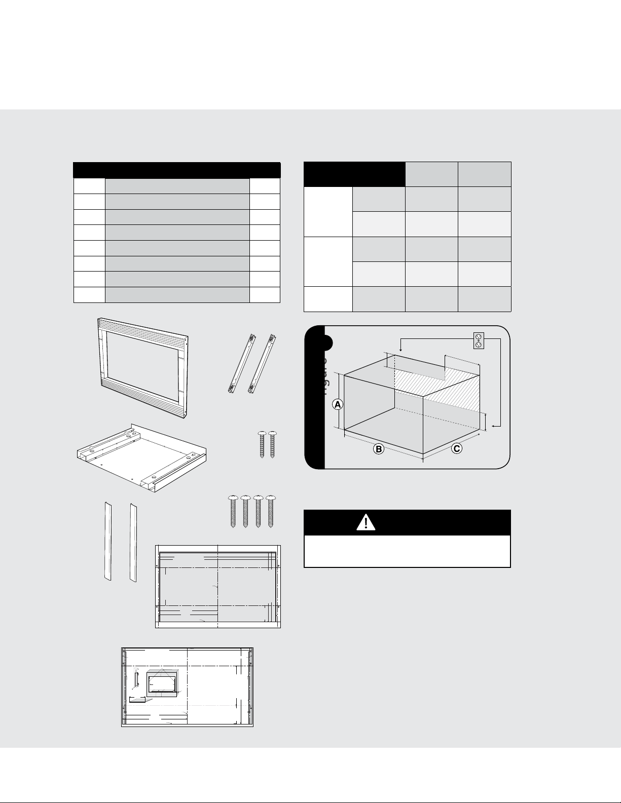
Parts Included in the Kit
Item Part Name QTY
1
Frame Assembly 1
2
Bottom Duct 1
3
Mounting Bracket 2
4
Screw A :1-3/16" length 2
5
Screw B: 1-3/4" length 4
6
Side Decoration
(Surface Mount Only)
2
7
Surface Mounting Template 1
8
Flush Mounting Template 1
Electrical Outlet Location
CAUTION
Outlet should NOT be in the shaded area as
indicated on figure 1.
1
figure
4"(10.2 cm)
4"(10.2 cm)
6"(15.2 cm)
NOTES:
• IftheDepth(C)dimensionisgreaterthan21"
(53.3 cm), the outlet location maybe inany
areaontherearwall.
• Theooroftheopeningshouldbeconstructed
ofplywoodstrongenoughtosupporttheweight
oftheovenandoorload(approximately100
pounds).Theoorshouldbelevelforproper
operation oftheoven.Besuretocheckthe
localbuildingcodeasitmayrequirethatthe
openingbeenclosedwithside,ceilingandrear
partition.Theproperfunctioningoftheoven
doesnotrequiretheenclosure.
Cabinet or Wall Cutout
Cutout Dimensions
Flush
Mount
Surface
Mount
Height A
Minimum
17-5/16"
(439.8mm)
16-9/16"
(420.7mm)
Maximum
N/A 16-13/16"
(427mm)
Width B
Minimum
29-5/8"
(752.5mm)
27-3/4"
(704.9mm)
Maximum
N/A 28"
(711.2mm)
Depth C
Minimum
20"
(503mm)
20"
(503mm)
Loading ...
Loading ...
Loading ...