Owner's Manual
II:RRFrSMRN I
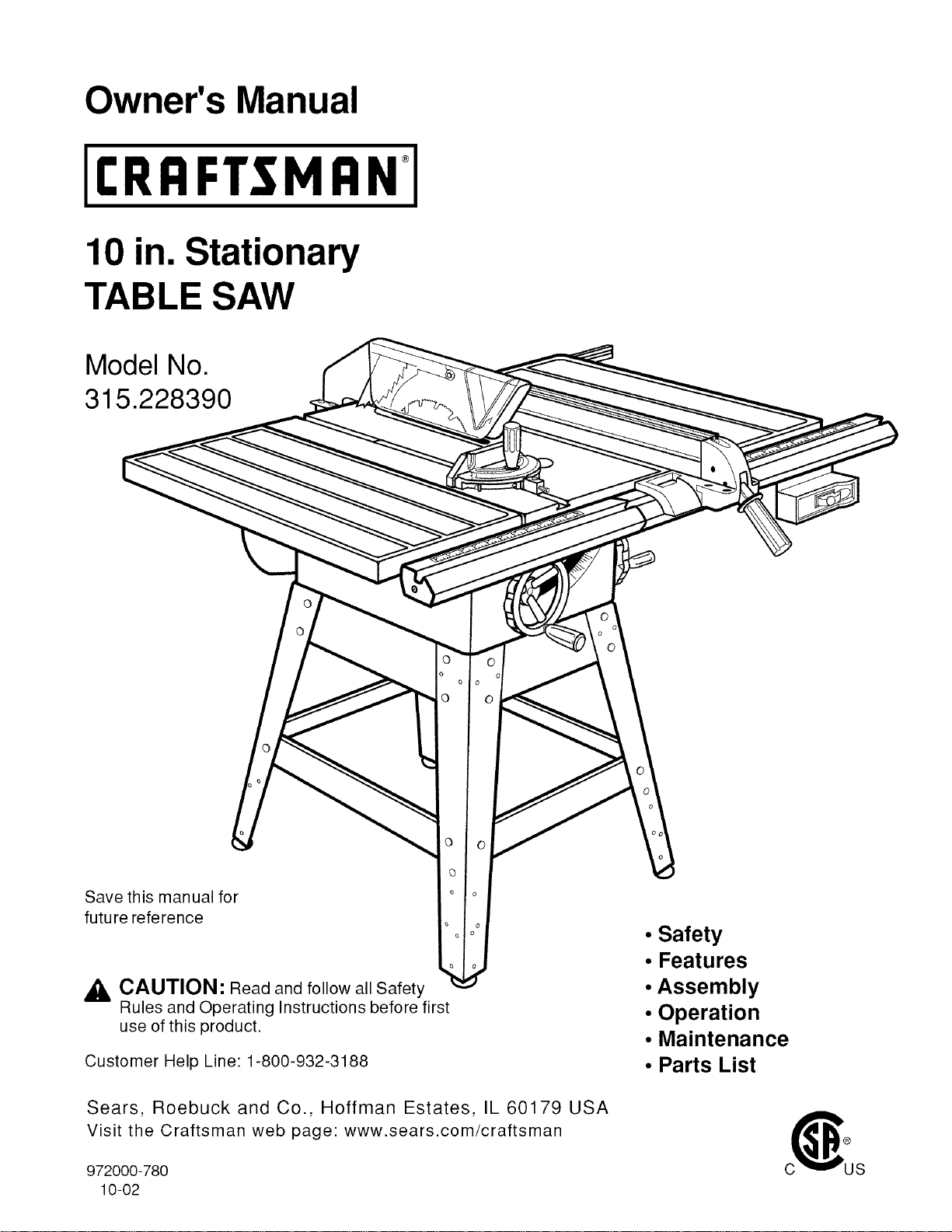
10 in. Stationary
TABLE SAW
Model No.
315.228390
Save this manual for
future reference
_, CAUTION: Read and follow all Safety
Rules and Operating Instructions before first
use of this product.
Customer Help Line: 1-800-932-3188
Sears, Roebuck and Co., Hoffman Estates, IL 60179 USA
Visit the Craftsman web page: www.sears.com/craftsman
972000-780
10-02
• Safety
• Features
•Assembly
• Operation
• Maintenance
• Parts List
FULL ONE YEAR WARRANTY ON CRAFTSMAN TABLE SAW
If this rRRFTSMRN Table Saw fails due to a defeat in material or workmanship within one year from the date
of purchase, Sears will repair it, free of charge.
Contact a Sears Service Center for repair.
If this product is used for commercial or rental purposes, this warranty applies only for 90 days from the date
of purchase.
This warranty gives you specific legal rights, and you may also have other rights which vary from state to
state.
Sears, Roebuck and Co., Dept. 817WA, Hoffman Estates, IL 60179
Your saw has many features for making cutting operations more pleasant and enjoyable. Safety, performance
and dependability have been given top priority in the design of this saw making it easy to maintain and operate.
,_ CAUTION: Carefully read through this entire owner's manual before using your new saw. Pay close
attention to the Rules For Safe Operation, and all Safety Alert Symbols, including Danger, Warning and
Caution. If you use your saw properly and only for what it is intended, you will enjoy years of safe, reliable
service.
,_ Look for this symbol to point out important safety precautions. It means attention!!! Your safety is involved.
_, WARNING:
The operation of any power tool can result in foreign objects being thrown into your eyes,
which can result in severe eye damage. Before beginning power tool operation, always
wear safety goggles or safety glasses with side shields and a full face shield when needed.
We recommend a Wide Vision Safety Mask for use over eyeglasses or standard safety
glasses with side shields, available at Sears Retail Stores.
CRRFTSMRN_TABLESAW315.228390
• Warranty and Introduction ............................................................................................................................. 2
• Table Of Contents ...................................................................................................................................... 2-3
• Rules For Safe Operation ........................................................................................................................... 4-6
• Electrical ....................................................................................................................................................... 7
• Glossary and Product Specifications ............................................................................................................ 8
• Unpacking and Accessories ......................................................................................................................... 9
• Loose Parts List .......................................................................................................................................... 10
• Small Parts List ...................................................................................................................................... 11-12
• Tools Needed .............................................................................................................................................. 13
• Labels ..................................................................................................................................................... 14-15
• Features ................................................................................................................................................. 16-17
• Assembly ................................................................................................................................................ 18-29
Installing Handwheels on Table Saw Base ................................................................................................. 18
Assembling Leg Stand ........................................................................................................................... 18-19
2

MountingtheLegStandontheTableSawBase........................................................................................19
AssemblingTableExtensions.....................................................................................................................20
AligningTableExtensions...........................................................................................................................20
InstallingtheRearRail................................................................................................................................21
InstallingtheFrontRail...............................................................................................................................22
AligningRipFenceandRails......................................................................................................................23
MountingtheMotor......................................................................................................................................23
InstallingtheBeltandBeltGuard...............................................................................................................24
CheckingtheThroatPlate...........................................................................................................................24
InstallingtheBladeGuard...........................................................................................................................25
AligningtheRivingKnifewiththeBlade.....................................................................................................26
CheckHeeling(Paralleling)oftheSawBladetotheMiterGageGroove..................................................27
CheckingRipFenceandBladeAlignment..................................................................................................28
CheckingSquarenessofExtensionTablestoSawTable..........................................................................29
• Adjustments............................................................................................................................................30-34
ReplacingtheBlade....................................................................................................................................30
Heeling(Paralleling)theSawbladetoMiterGageGroove....................................................................31-32
SettingtheBevelStopsandIndicator....................................................................................................32-33
AdjustingtheMiterGage.............................................................................................................................33
Removing/ Replacing the Throat Plate ...................................................................................................... 34
• Basic Operation of the Table Saw ......................................................................................................... 35-42
Causes of Kickback .................................................................................................................................... 35
Avoiding Kickback ....................................................................................................................................... 35
Cutting Aids ................................................................................................................................................. 35
Types of Cuts .............................................................................................................................................. 36
Making a Cross Cut ..................................................................................................................................... 37
Making a Rip Cut .................................................................................................................................... 37-38
Making a Miter Cut ...................................................................................................................................... 38
Making a Bevel Cross Cut ..................................................................................................................... 38-39
Making a Bevel Rip Cut ............................................................................................................................... 39
Making a Compound (Bevel) Miter Cut ....................................................................................................... 40
Making a Large Panel Cut ........................................................................................................................... 41
Making a Non-Through Cut ......................................................................................................................... 41
Making a Dado Cut ...................................................................................................................................... 42
• Maintenance ................................................................................................................................................ 43
• Lubrication ................................................................................................................................................... 43
• Troubleshooting ...................................................................................................................................... 44-46
• Exploded View and Repair Parts List ..................................................................................................... 48-65
• Parts Ordering / Service ................................................................................................................ back page
3 CRRFTSM RN_TABLE SAW 315.228390

The purpose of safety symbols is to attract your attention to possible dangers. The safety symbols, and the
explanations with them, deserve your careful attention and understanding. The safety warnings do not by
themselves eliminate any danger. The instructions or warnings they give are not substitutes for proper accident
prevention measures.
SYMBOL MEANING
,&
A
a,
,&
Note:
SAFETY ALERT SYMBOL
Indicates danger, warning, or caution. May be used in conjunction with other symbols or
pictographs.
DANGER: Failure to obey a safety warning will result in serious injury to yourself or to others.
Always follow the safety precautions to reduce the risk of fire, electric shock and personal injury.
WARNING: Failure to obey a safety warning can result in serious injury to yourself or to others.
Always follow the safety precautions to reduce the risk of fire, electric shock and personal injury.
CAUTION: Failure to obey a safety warning may result in property damage or personal injury to
yourself or to others. Always follow the safety precautions to reduce the risk of fire, electric shock
and personal injury.
Advises you of information or instructions vital to the operation or maintenance of the equipment.
IMPORTANT
Servicing requires extreme care and knowledge of the
system and should be performed only by a qualified
service technician. For service we suggest you return
the tool to your nearest Sears store or repair center.
Always use original factory replacement parts when
servicing.
A
WARNING: Do not attempt to operate this tool
until you have read thoroughly and understand
completely all instructions, safety rules, etc.
contained in this manual. Failure to comply can
result in accidents involving fire, electrical shock,
or serious personal injury. Save the owner's
manual and review frequently for continuing safe
operation, and instructing others who may use
this tool.
READ ALL INSTRUCTIONS
• KNOW YOUR POWER TOOL. Read the owner's
manual carefully. Learn the saw's applications
and limitations as well as the specific potential
hazards related to this tool.
• DO NOT USE IN DANGEROUS ENVIRON-
MENT. Do not use power tools near gasoline or
other flammable liquids, in damp or wet loca-
tions, or expose them to rain. Keep the work
area well lit.
• MAKE WORKSHOP CHILD-PROOF with
padlocks and master switches or by removing
starter keys.
• KEEP CHILDREN AND VISITORS AWAY. All
visitors should wear safety glasses and be kept
a safe distance from work area. Do not let
visitors contact tool or extension cord while
operating.
• KEEP THE WORK AREA CLEAN. Cluttered
work areas and work benches invite accidents.
DO NOT leave tools or pieces of wood on the
saw while it is in operation.
• MAINTAIN TOOLS WITH CARE. Keep tools
sharp and clean for better and safer perfor-
mance. Follow instructions for lubricating and
changing accessories.
• USE THE RIGHT TOOL FOR THE JOB. Do not
force the tool or attachment to do a job it was
not designed for. Use it only the way it was
intended.
• DRESS PROPERLY. Do not wear loose cloth-
ing, gloves, neckties, rings, bracelets, or other
jewelry. They can get caught and draw you into
moving parts. Rubber gloves and nonslip
footwear are recommended. Also wear protec-
tive hair covering to contain long hair.
• ALWAYS WEAR SAFETY GLASSES WITH
SIDE SHIELDS. Everyday eyeglasses have only
impact-resistant lenses; they are NOT safety
glasses.
• NEVER STAND ON TOOL. Serious injury could
occur if the tool is tipped or if the blade is
unintentionally contacted.
CRRFTSMRN* TABLESAW315.228390 4
RULES FOR SAFE OPERATION (Continued)
• DO NOT OVERREACH. Keep proper footing and
balance at all times.
• SECURE WORK. Use clamps or a vise to hold
work when practical. It's safer than using your
hand and frees both hands to operate tool.
• USE THE PROPER EXTENSION CORD. Make
sure your extension cord is in good condition.
Use only a cord heavy enough to carry the
current your product will draw. An undersized
cord will cause a drop in line voltage resulting in
loss of power and overheating. A wire gage size
(A.W.G.) of at least 14 is recommended for an
extension cord 25 feet or less in length. If in
doubt, use the next heavier gage. The smaller
the gage number, the heavier the cord.
• AVOID ACCIDENTAL STARTING. Be sure
switch is off when plugging in.
• REMOVE WRENCHES AND ADJUSTING
KEYS. Get in the habit of checking - before
turning on tool - that hex keys and adjusting
wrenches are removed from tool.
• CHECK DAMAGED PARTS. Before using the
tool again, check any damaged parts, including
guards, for proper operation and performance.
Check alignment of moving parts, binding of
moving parts, breakage of parts, saw stability,
mounting and any other conditions that may
affect its operation. A damaged part must be
properly repaired or replaced by a qualified
service technician at a Sears store or repair
center to avoid risk of personal injury.
• USE ONLY CORRECT BLADES. Use the right
blade size, style and cutting speed for the
material and the type of cut. Blade teeth should
point down toward the front of the table.
• USE RECOMMENDED ACCESSORIES. Using
improper accessories may risk injury.
• USE ONLY SEARS REPLACEMENT PARTS.
All repairs, whether electrical or mechanical,
should be made by a qualified service technician
at a Sears store or repair center.
• KEEP GUARDS IN PLACE and in good working
order. This includes the blade guard, riving
knife, and anti-kickback pawls.
• CHECK DIRECTION OF FEED. Feed work into
a blade or cutter against the direction of rotation
of the blade or cutter only.
• DISCONNECT ALL TOOLS. When not in use,
before servicing, or when changing attachments,
blades, bits, cutters, etc., all tools should be
disconnected from power supply.
• DO NOT FORCE THE TOOL. It will do the job
better and more safely at the rate for which it
was designed.
• NEVER LEAVE TOOL RUNNING UNAT-
TENDED. TURN THE POWER OFF. Do not
leave tool until it comes to a complete stop.
• BEFORE MOUNTING, DISCONNECTING OR
REMOUNTING THE MOTOR; unplug the saw
and remove the switch key.
,&
WARNING: When servicing, use only identical
Craftsman replacement parts. Use of any other
parts may create a hazard or cause product
damage.
• NEVER USE THIS TOOL IN AN EXPLOSIVE
ATMOSPHERE. Normal sparking of the motor
could ignite fumes.
• MAKE SURE THE WORK AREA HAS AMPLE
LIGHTING to see the work and that no obstruc-
tions will interfere with safe operation BEFORE
performing any work using this tool.
• DO NOT USE TOOL IF SWITCH DOES NOT
TURN IT ON AND OFF. Have defective
switches replaced by a qualified service techni-
cian at a Sears store or repair center.
• GUARD AGAINST ELECTRICAL SHOCK by
preventing body contact with grounded surfaces
such as pipes, radiators, ranges, refrigerator
enclosures.
• GROUND ALL TOOLS. See Electrical page.
• WEAR A DUST MASK to keep from inhaling
fine particles.
• PROTECT YOUR HEARING. Wear hearing
protection during extended periods of operation.
• DO NOT OPERATE THIS TOOL WHILE UN-
DER THE INFLUENCE OF DRUGS, ALCOHOL,
OR ANY MEDICATION.
STAY ALERT AND EXERCISE CONTROL.
Watch what you are doing and use common
sense. Do not operate tool when you are
tired. Do not rush.
• AVOID AWKWARD OPERATIONS AND HAND
POSITIONS where a sudden slip could cause
your hand to move into the blade. ALWAYS
make sure you have good balance.
• ALWAYS SUPPORT LARGE WORK PIECES
while cutting to minimize risk of blade pinching
and kickback. Saw may slip, walk or slide while
cutting large or heavy boards.
• GUARD AGAINST KICKBACK. Kickback can
occur when the blade stalls, driving the work
piece back toward the operator, tt can pull your
hand into the blade, resulting in serious personal
injury. Stay out of the blade path and turn switch
off immediately if blade binds or stalls.
5 r RBF1"$1_BN* TABLESAW315.228390
RULES FOR SAFE OPERATION (Continued)
• USE A SUPPORT FOR THE SIDES AND BACK
OF THE SAW TABLE when sawing wide or long
workpieces. Use a sturdy "outrigger" support if a
table extension is more than 24 inches long and
is attached to the saw, to prevent tipping.
• CUT ONLY WOOD, PLASTIC OR WOOD-LIKE
MATERIALS. Do not cut metal.
• NEVER cut more than one piece at a time. DO
NOT STACK more than one workpiece on the
saw table at a time.
• DO NOT REMOVE THE SAW'S BLADE
GUARDS. Never operate the saw with any
guard or cover removed. Make sure all guards
are operating properly before each use.
• NEVER PERFORM ANY OPERATION FREE-
HAND. Always place the workpiece to be cut on
the saw table and position it firmly against the
fence as a backstop.
• USE THE RIP FENCE. Always use a fence or
straight edge guide when ripping.
• BEFORE MAKING A CUT, be sure all adjust-
ments are secure.
• BE SURE THE BLADE PATH IS FREE OF
NAILS. Inspect for and remove all nails from
lumber before cutting.
• BE SURE THE BLADE CLEARS THE
WORKPIECE. Never start the saw with the
blade touching the workpiece.
• KEEP HANDS AWAY FROM CUTTING AREA.
Do not reach underneath work or in blade cutting
path with your hands and fingers for any reason.
Always turn the power off.
• USE A PUSHBLOCK OR PUSH STICK for
workpieces so small that your fingers go under
the blade guard. NEVER TOUCH BLADE or
other moving parts during use, for any reason.
,4_ WARNING: Blade coasts after being turned off.
• ALLOW THE MOTOR TO COME UP TO FULL
SPEED before starting a cut to avoid blade
binding or stalling.
• ALWAYS PUSH THE WORKPIECE; never pull
it toward the saw.
• DO NOT FEED THE MATERIAL TOO
QUICKLY. Do not force the workpiece against
the blade.
• ALWAYS TURN OFF SAW before disconnect-
ing it, to avoid accidental starting when recon-
necting to power supply. NEVER leave the table
saw unattended while connected to a power
source.
• BEFORE CHANGING THE SETUP, REMOVING
COVERS, GUARDS, OR BLADE; unplug the
saw and remove the switch key.
• KEEP TOOL DRY, CLEAN, AND FREE FROM
OIL AND GREASE. Always use a clean cloth
when cleaning. Never use brake fluids, gasoline,
petroleum-based products, or any solvents to
clean tool.
• KEEP BLADES CLEAN, SHARP AND WITH
SUFFICIENT SET. Sharp blades minimize
stalling and kickback.
• USE ONLY OUTDOOR EXTENSION CORDS.
Use only extension cords with the marking
"Acceptable for use with outdoor appliances;
store cords indoors while not in use." Use
extension cords with an electrical rating not less
than the saw's rating. Always disconnect the
extension cord from the outlet before discon-
necting the product from the extension cord.
• INSPECT TOOL CORDS AND EXTENSION
CORDS PERIODICALLY and, if damaged, have
repaired by a qualified service technician at a
Sears store or repair center. Stay constantly
aware of cord location and keep it well away
from the moving blade.
• DO NOT ABUSE CORD. Never yank cord to
disconnect it from receptacle. Keep cord from
heat, oil, and sharp edges.
• SAVE THESE INSTRUCTIONS. Refer to them
frequently and use to instruct other users. If you
loan someone this tool, loan them these instruc-
tions also.
A
WARNING: Some dust created by power
sanding, sawing, grinding, drilling, and other
construction activities contains chemicals
known to cause cancer, birth defects or other
reproductive harm. Some examples of these
chemicals are:
• lead from lead-based paints,
• crystalline silica from bricks and cement
and other masonry products, and
• arsenic and chromium from chemically-
treated lumber.
Your risk from these exposures varies,
depending on how often you do this type of
work. To reduce your exposure to these
chemicals: work in a well ventilated area, and
work with approved safety equipment, such as
those dust masks that are specially designed
to filter out microscopic particles.
SAVE THESE INSTRUCTIONS
CRRFI"$1_tRN_TABLESAW315.228390 6
EXTENSION CORDS
Use only 3-wire extension cords that have 3-prong
grounding plugs and 3-pole receptacles that accept
the tool's plug. When using a power tool at a consid-
erable distance from the power source, use an
extension cord heavy enough to carry the current that
the tool will draw. An undersized extension cord will
cause a drop in line voltage, resulting in a loss of
power and causing the motor to overheat. Use the
chart provided below to determine the minimum wire
size required in an extension cord. Only round jack-
eted cords listed by Underwriter's Laboratories (UL)
should be used.
Length of Extension Cord Wire Size (A.W.G.)
Up to 25 feet 14
26-100 feet 12
When working with the tool outdoors, use an exten-
sion cord that is designed for outside use. This is
indicated by the letters WA on the cord's jacket.
Before using an extension cord, inspect it for loose or
exposed wires and cut or worn insulation.
,_ CAUTION: Keep the cord away from the cutting
area and position the cord so that it will not be
caught on lumber, tools, or other objects during
cutting operations.
ELECTRICAL CONNECTION
Your Sears Craftsman Table Saw is powered by a
precision built electric motor. It should be connected
to a power supply that is 120 volts, 60 Hz, AC only
(normal household current). Do not operate this tool
on direct current (DC). A substantial voltage drop will
cause a loss of power and the motor will overheat. If
the saw does not operate when plugged into an
outlet, double check the power supply.
SPEED AND WIRING
The no-load speed of your table saw is approximately
3,600 rpm. This speed is not constant and decreases
under a load or with lower voltage. For voltage, the
wiring in a shop is as important as the motor's horse-
power rating. A line intended only for lights cannot
properly carry a power tool motor. Wire that is heavy
enough for a short distance will be too light for a
greater distance. A line that can support one power
tool may not be able to support two or three tools.
GROUNDING INSTRUCTIONS
In the event of a malfunction or breakdown, grounding
provides a path of least resistance for electric current
to reduce the risk of electric shock. This tool is
equipped with an electric cord having an equipment-
grounding conductor and a grounding plug. The plug
must be plugged into a matching outlet that is properly
installed and grounded in accordance with all local
codes and ordinances.
Do not modify the plug provided. If it will not fit the
outlet, have the proper outlet installed by a qualified
electrician. Improper connection of the equipment-
grounding conductor can result in a risk of electric
shock. The conductor with insulation having an outer
surface that is green with or without yellow stripes is
the equipment-grounding conductor. If repair or
replacement of the electric cord or plug is necessary,
do not connect the equipment-grounding conductor to
a live terminal.
Check with a qualified electrician or service personnel
if the grounding instructions are not completely
understood, or if in doubt as to whether the tool is
properly grounded.
Repair or replace a damaged or worn cord immedi-
ately.
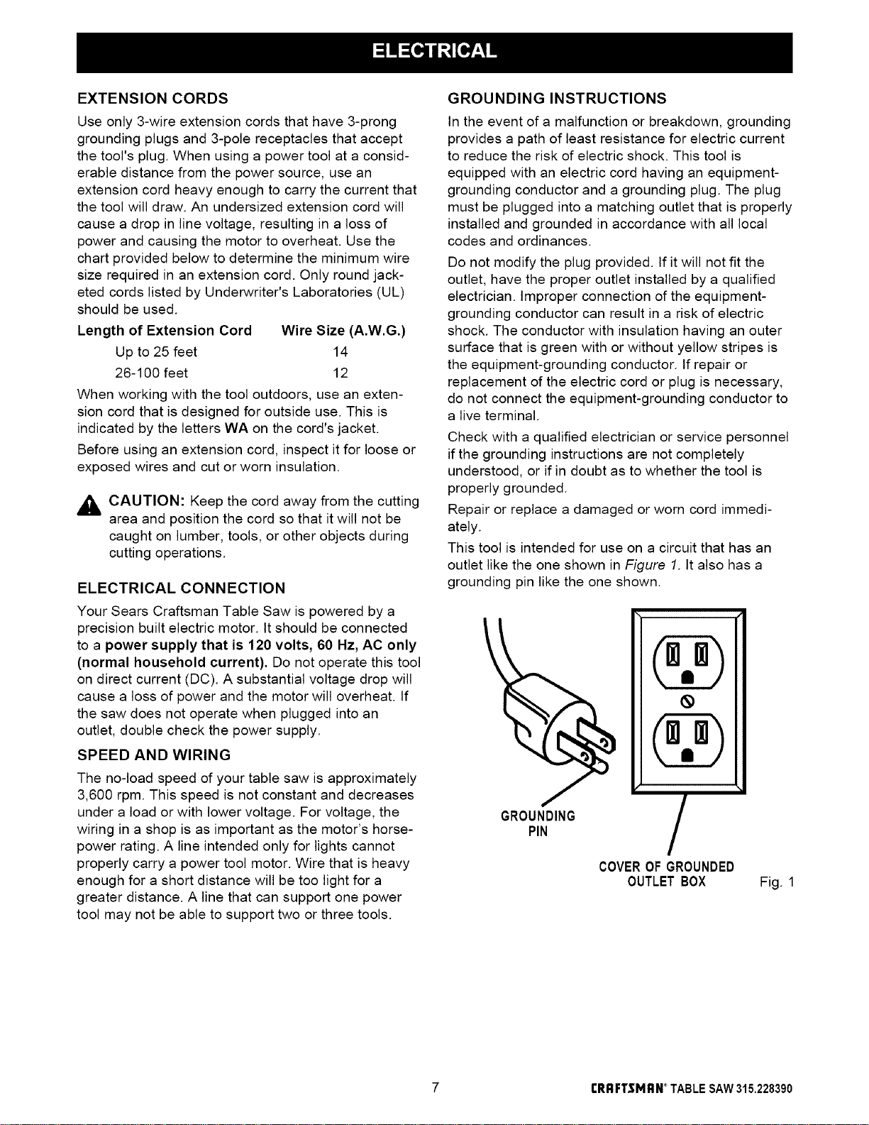
This tool is intended for use on a circuit that has an
outlet like the one shown in Figure 1. It also has a
grounding pin like the one shown.
GROUNDING
PIN
COVEROF GROUNDED
OUTLETBOX Fig. 1
7 r RRFT$1_RN* TABLESAW315.228390
Anti-Kickback Pawls
Toothed safety devices behind the blade designed to
stop a workpiece from being kicked back at the
operator during a ripping operation,
Arbor
The shaft on which a blade or cutting tool is mounted,
Bevel Cut
A cutting operation made with the blade at any angle
other than 90° to the saw table,
Compound Cut
A cut with both a miter angle and a bevel angle,
Crosscut
A cutting operation made across the grain or the width
of the workpiece.
Dado
A non-through cut that gives a square notch or trough;
requires a special blade,
Featherboard
A device to help guide workpieces during rip cuts,
Freehand (for table saw)
Dangerous practice of making a cut without using rip
or miter fences. See Safety Rules,
Gum
A sticky, sap-based residue from wood products.
Heel
Alignment of the blade.
Kerf
The material removed by the blade in a through cut or
the slot produced by the blade in a non-through cut.
Kickback
A hazard that can occur when blade binds or stalls,
throwing workpiece back toward operator.
Leading End
The end of the workpiece pushed into the cutting tool
first.
Miter Cut
A cutting operation made with the miter gage at any
angle other than 0°.
Molding
A non-through cut that gives a varied shape to the
workpiece and requires a special blade,
Push Stick
A device used to feed the workpiece through the saw
blade during narrow cutting operations. It helps keep
the operator's hands well away from the blade,
Rabbet
A notch in the edge of a workpiece.
Resaw
A cutting operation to reduce the thickness of the
workpiece in order to make thinner pieces.
Resin
A sticky, sap-based substance,
Rip Cut
A cut made with the the grain of the workpiece.
Sawblade Path
The area directly in line with the blade -- over, under,
behind, or in front of it, Also, the workpiece area
which will be or has been cut by the blade.
Set
The distance that the tip of the saw blade tooth is bent
(or set) outward from the face of the blade.
Throw-Back
Saw throwing back a workpiece; similar to kickback,
Through Sawing
Any cutting operation where the blade extends
completely through the workpiece.
Trailing End
The workpiece end last cut by the blade in a rip cut.
Workpiece
The item on which the cutting operation is being done.
The surfaces of a workpiece are commonly referred to
as faces, ends, and edges,
Worktable
The surface on which the workpiece rests while
performing a cutting operation,
Blade Arbor 5/8 in.
Blade Diameter 10 in,
Blade Tilt 0 ° - 45 °
Table Size without table extensions 20 in, x 27 in.
Table Size with table extensions 44 in, x 27 in.
Rating 13 Amperes, 1,5 HP
(3 HP max, developed)
Input 120 V, 60 Hz - AC only
No Load Speed 3,600 RPM
Cutting Capacity with Miter at 0°/Bevel 0° 3-3/8 in,
Cutting Capacity with Miter at 0°/Bevel 45°: 2-1/4 in.
rRRFTSMRH ° TABLESAW315.228390 8
Your new table saw has been designed to give you
many years of high quality performance. To insure
this goal, proper care and treatment is important.
Careful treatment begins with removing all parts from
the carton and checking them against the list of loose
parts. The long box contains the rails. The large box ,_
holds all other parts, which are detailed in the Loose
u
Parts List.
• Separate the saw and all parts from the packing
materials and check each against the packing list,
especially the small parts that can be hidden in the
packing material.
Note: Do not discard the packing materials until you
A
have carefully inspected the saw, identified all
parts, and satisfactorily operated your new saw.
,_k WARNING: Never use gasoline, naptha, or
other highly volatile solvents. Do not ever let
brake fluids, gasoline, petroleum-based
products, or penetrating oils contact plastic parts.
Such chemicals can weaken or destroy plastic.
• Remove the wax paper covering on the table. Use
any ordinary household type grease and spot
remover. Immediately apply a coat of paste wax to
the table and table extensions.
WARNING: To prevent accidental starting that
could cause possible serious personal injury,
assemble all parts to your saw before connecting
it to power supply. Saw should never be
connected to power supply when you are
assembling parts, making adjustments, installing
or removing blades, or when not in use.
WARNING: tf any parts are missing, do not
operate this tool until the missing parts are
replaced. Failure to do so could result in possible
serious personal injury.
The following recommended accessories are currently available at Sears Retail Stores.
Fence Guide System
Guide Master
Box Joint & Miter Guide
Universal Jig
Taper Jig
10 in. Sanding Disc
8 in. Sanding Disc
Elite Dado
Excalibur Dado
7 in. Adj. Dado 36 tip
7 in. Adj. Dado 24 tip
7 in. Stack Steel Dado
7 in. x 9/16 in. Stack Dado
7 in. Molding Head Set
2 Bit Molding Head Set
Saw Baskets
Jointer Clamps
Specialty Throat Plate
Miter Gage Hold Down Clamp
Align-A-Rip XRC Rip Fence
Dust Collection System
Accessory Table
,_ WARNING: The use of attachments or accessories not listed might be hazardous.
9 I:RI:IFT$1_IRN _TABLE SAW 315.228390
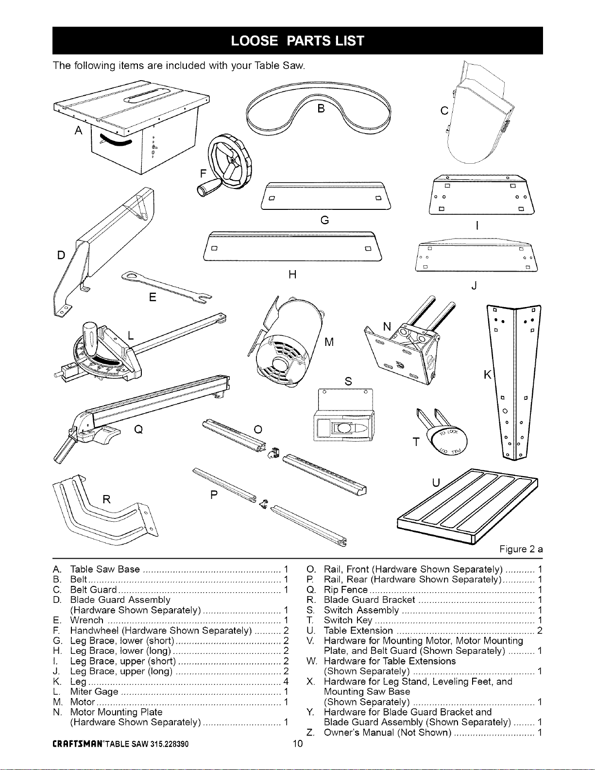
The following items are included with your Table Saw.
D
A
G
C
\
I
J
Figure 2 a
A. Table Saw Base ................................................... 1
B. Belt ....................................................................... 1
C. Belt Guard ............................................................ 1
D. Blade Guard Assembly
(Hardware Shown Separately) ............................. 1
E. Wrench ................................................................ 1
R Handwheel (Hardware Shown Separately) .......... 2
G. Leg Brace, lower (short) ....................................... 2
H. Leg Brace, lower (long) ........................................ 2
I. Leg Brace, upper (short) ...................................... 2
J. Leg Brace, upper (long) ....................................... 2
K. Leg ....................................................................... 4
L. Miter Gage ........................................................... 1
M. Motor .................................................................... 1
N. Motor Mounting Plate
(Hardware Shown Separately) ............................. 1
CRRFTSMRN°TABLESAW315.228390
Y.
Z.
10
O. Rail, Front (Hardware Shown Separately) ........... 1
R Rail, Rear (Hardware Shown Separately) ............ 1
Q. Rip Fence ............................................................. 1
R. Blade Guard Bracket ........................................... 1
S. Switch Assembly ................................................. 1
T. Switch Key ........................................................... 1
U. Table Extension ................................................... 2
V. Hardware for Mounting Motor, Motor Mounting
Plate, and Belt Guard (Shown Separately) .......... 1
W. Hardware for Table Extensions
(Shown Separately) ............................................. 1
X. Hardware for Leg Stand, Leveling Feet, and
Mounting Saw Base
(Shown Separately) ............................................. 1
Hardware for Blade Guard Bracket and
Blade Guard Assembly (Shown Separately) ........ 1
Owner's Manual (Not Shown) .............................. 1
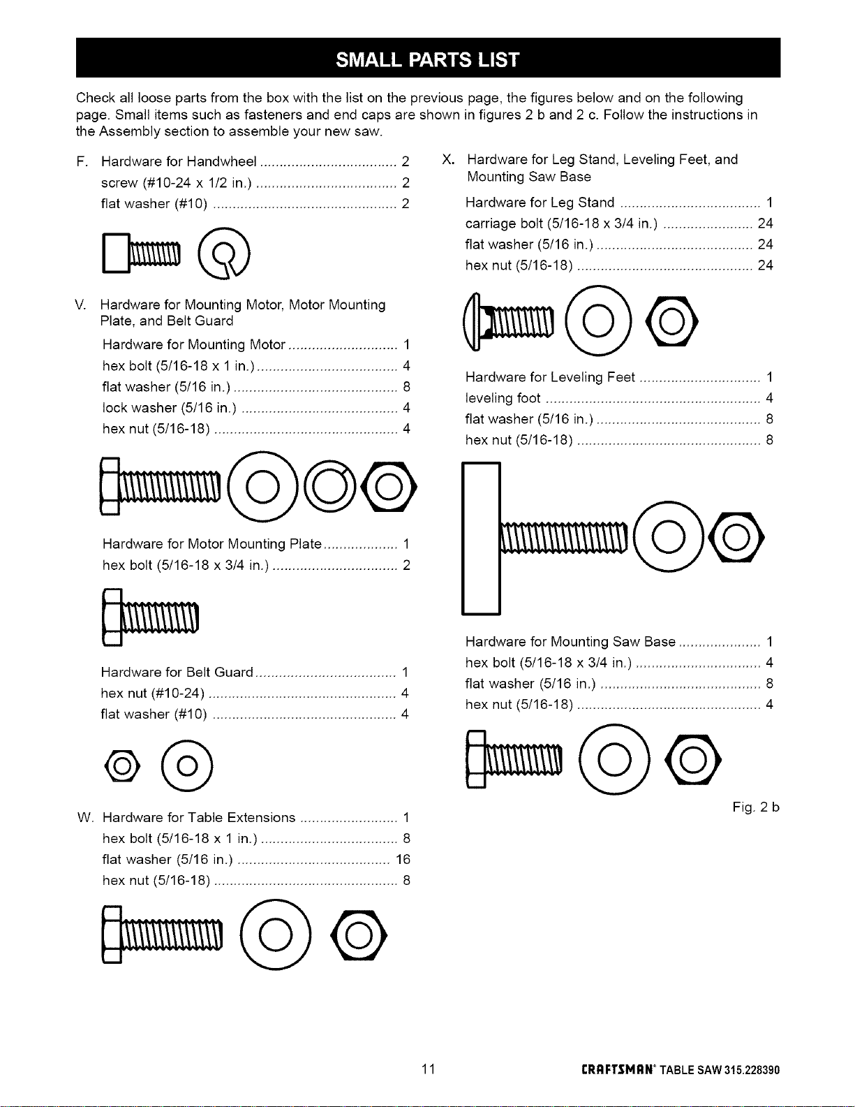
Checkallloosepartsfromtheboxwiththelistonthepreviouspage,thefiguresbelowandonthefollowing
page.Smallitemssuchasfastenersandendcapsareshowninfigures2band2c.Followtheinstructionsin
theAssemblysectiontoassembleyournewsaw.
F. HardwareforHandwheel...................................2 X.
screw(#10-24x 1/2in.)....................................2
flatwasher(#10)...............................................2
V.
Hardware for Mounting Motor, Motor Mounting
Plate, and Belt Guard
Hardware for Mounting Motor ............................ 1
hex bolt (5/16-18 x 1 in.) .................................... 4
flat washer (5/16 in.) .......................................... 8
lock washer (5/16 in.) ........................................ 4
hex nut (5/16-18) ............................................... 4
Hardware for Motor Mounting Plate ................... 1
hex bolt (5/16-18 x 3/4 in.) ................................ 2
Hardware for Leg Stand, Leveling Feet, and
Mounting Saw Base
Hardware for Leg Stand .................................... 1
carriage bolt (5/16-18 x 3/4 in.) ....................... 24
flat washer (5/16 in.) ........................................ 24
hex nut (5/16-18) ............................................. 24
Hardware for Leveling Feet ............................... 1
leveling foot ....................................................... 4
flat washer (5/16 in.) .......................................... 8
hex nut (5/16-18) ............................................... 8
W.
Hardware for Belt Guard .................................... 1
hex nut (#10-24) ................................................ 4
flat washer (#10) ............................................... 4
Q®
Hardware for Table Extensions ......................... 1
hex bolt (5/16-18 x 1 in.) ................................... 8
flat washer (5/16 in.) ....................................... 16
hex nut (5/16-18) ............................................... 8
Hardware for Mounting Saw Base ..................... 1
hex bolt (5/16-18 x 3/4 in.) ................................ 4
flat washer (5/16 in.) ......................................... 8
hex nut (5/16-18) ............................................... 4
Fig. 2 b
11 tRRFTSMRN _TABLESAW315.228390
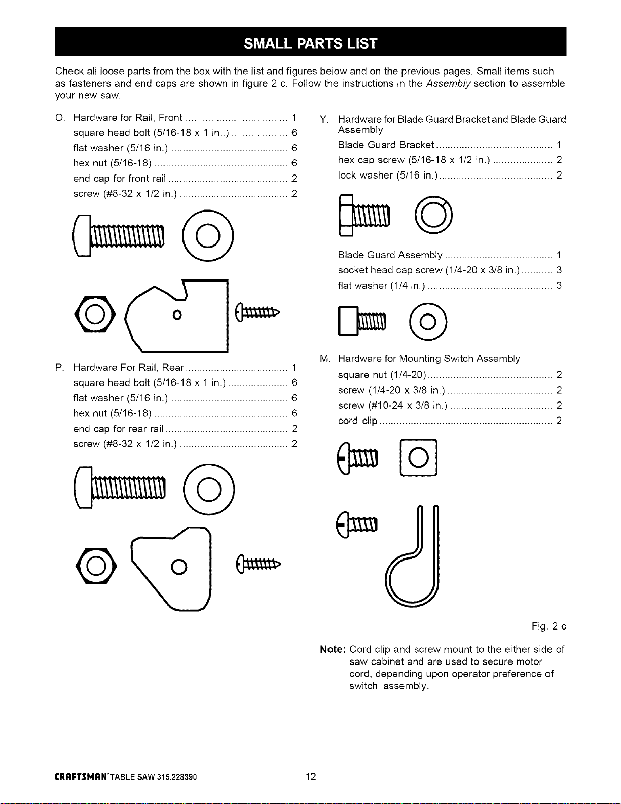
Check all loose parts from the box with the list and figures below and on the previous pages. Small items such
as fasteners and end caps are shown in figure 2 c. Follow the instructions in the Assembly section to assemble
your new saw.
O. Hardware for Rail, Front .................................... 1 y.
square head bolt (5/16-18 x 1 in..) .................... 6
flat washer (5/16 in.) ......................................... 6
hex nut (5/16-18) ............................................... 6
end cap for front rail .......................................... 2
screw (#8-32 x 1/2 in.) ...................................... 2
P.
Hardware For Rail, Rear .................................... 1
square head bolt (5/16-18 x 1 in.) ..................... 6
flat washer (5/16 in.) ......................................... 6
hex nut (5/16-18) ............................................... 6
end cap for rear rail ........................................... 2
screw (#8-32 x 1/2 in.) ...................................... 2
M.
Hardware for Blade Guard Bracket and Blade Guard
Assembly
Blade Guard Bracket ......................................... 1
hex cap screw (5/16-18 x 1/2 in.) ..................... 2
lock washer (5/16 in.) ........................................ 2
Blade Guard Assembly ...................................... 1
socket head cap screw (1/4-20 x 3/8 in.) ........... 3
flat washer (1/4 in.) ............................................ 3
Hardware for Mounting Switch Assembly
square nut (1/4-20) ............................................ 2
screw (1/4-20 x 3/8 in.) ..................................... 2
screw (#10-24 x 3/8 in.) .................................... 2
cord clip ............................................................. 2
Fig. 2 c
Note: Cord clip and screw mount to the either side of
saw cabinet and are used to secure motor
cord, depending upon operator preference of
switch assembly.
rRAFTSMAN°TABLE SAW315.228390 12
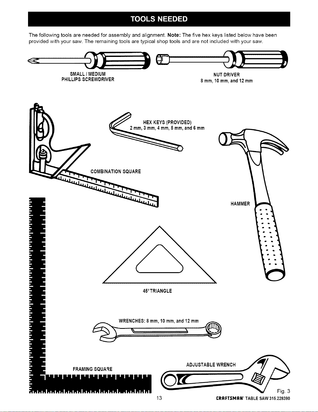
The following tools are needed for assembly and alignment. Note: The five hex keys listed below have been
provided with your saw. The remaining tools are typical shop tools and are not included with your saw.
8MALL/ MEDIUM
PHILLIPSSCREWDRIVER
NUTDRIVER
8 ram,10 ram,and12 mm
HEXKEY8 (PROVIDED)
and6 mm
COMBINATIONSQUARE
HAMMER
45°TRIANGLE
WREN_HES:8 ram,10 ram,and12 mm
,_, "
FRAMINGSQUARE
13 rRRF'rSMRN*TABLESAW315.228390
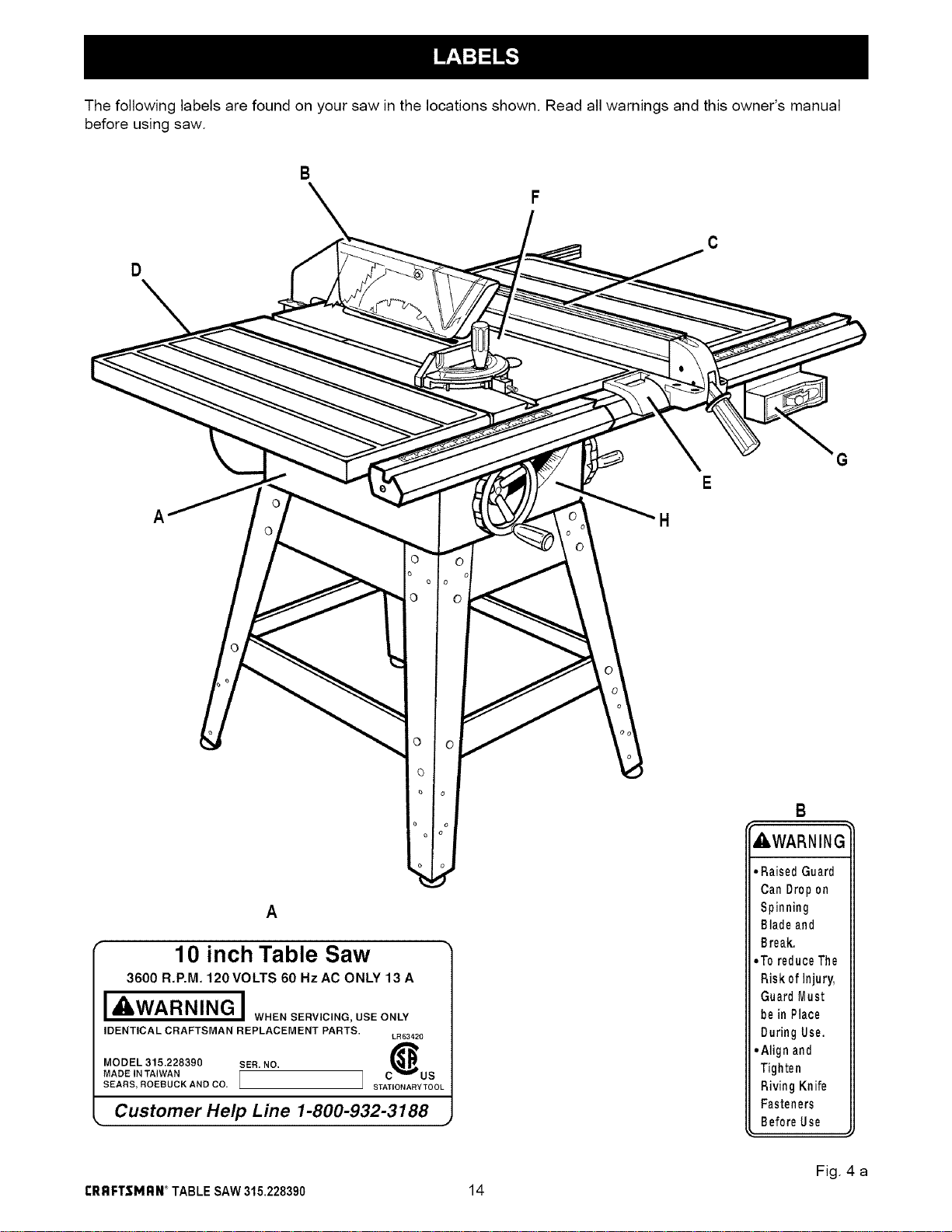
The following labels are found on your saw in the locations shown. Read all warnings and this owner's manual
before using saw.
B
D
C
A
A
10 inch Table Saw
3600 R.P.M. 120 VOLTS 60 Hz AC ONLY 13 A
, WARNING I WHEN SERVICING, USE ONLY
IDENTICAL CRAFTSMAN REPLACEMENT PARTS.
LR63420
MODEL 315.228390 SER, NO. (_
MADE IN TAIWAN [ ] C "_eB" US
SEARS, ROEBUCK AND CO. STATIONARYTOOI
Customer Help Line 1-800-932-3188
A, WARNING
• RaisedGuard
CanDropon
Spinning
Bladeand
Break,
• Toreduce The
Riskof Injury,
Guard Must
bein Place
During Use.
• Align and
Tighten
Riving Knife
Fasteners
BeforeUse
Fig. 4 a
CRRFTSMRN_TABLESAW315.228390 14
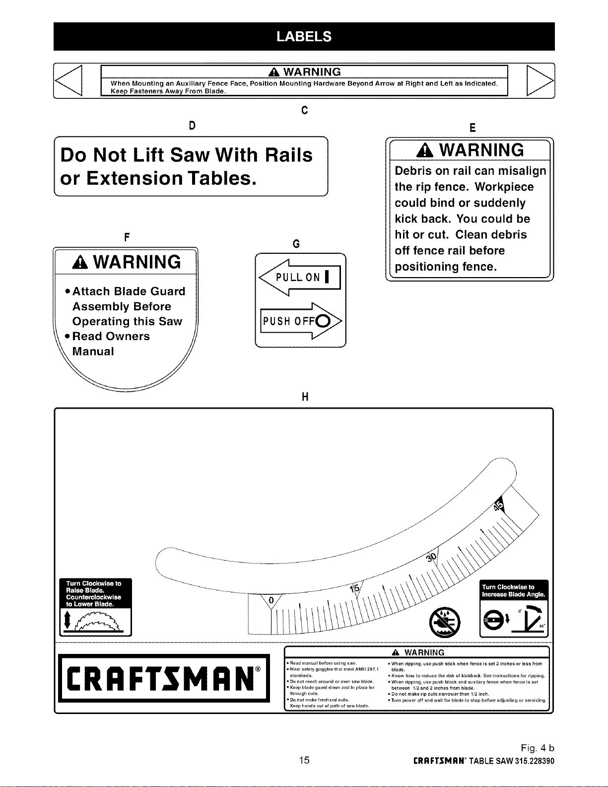
[<_ t _k WARNING
When Mounting an Auxiliary Fence Face, Position Mounting Hardware Beyond Arrow at Right and Left as indicated,
Keep Fasteners Away From Blade.
C
D
IDo Not Lift Saw With Railsor Extension Tables.
WARNING
• Attach Blade Guard
Assembly Before
Operating this Saw
• Read Owners
G
LL ON I
PUSH OFFOI_
WARNING
Debris on rail can misalign
the rip fence. Workpiece
could bind or suddenly
kick back. You could be
hit or cut. Clean debris
off fence rail before
positioning fence•
II:RRFTSMRN
I I* Read manual before using saw.
• Wear safety goggles that meet ANSI Z87.1
standards.
• Do not reach around or over saw blade.
• Keep blade guard down and in place for
through cuts.
• Do not make freehand cuts.
Keep hands out of path of saw blade.
_. WARNING
• When ripping, use push stick when fence is set 2 inches or less from
blade.
• Know how to reduce the risk of kickback. See instructions for ripping.
• When ripping, use push block and auxilary fence when fence is set
between 1/2 and 2 inches from blade.
• DO not make rip cuts narrower than 1/2 inch.
• Turn power off and wait for blade to stop before adjusting or servicing.
Fig. 4 b
15 rRRFI"$MRN _TABLE SAW315.228390
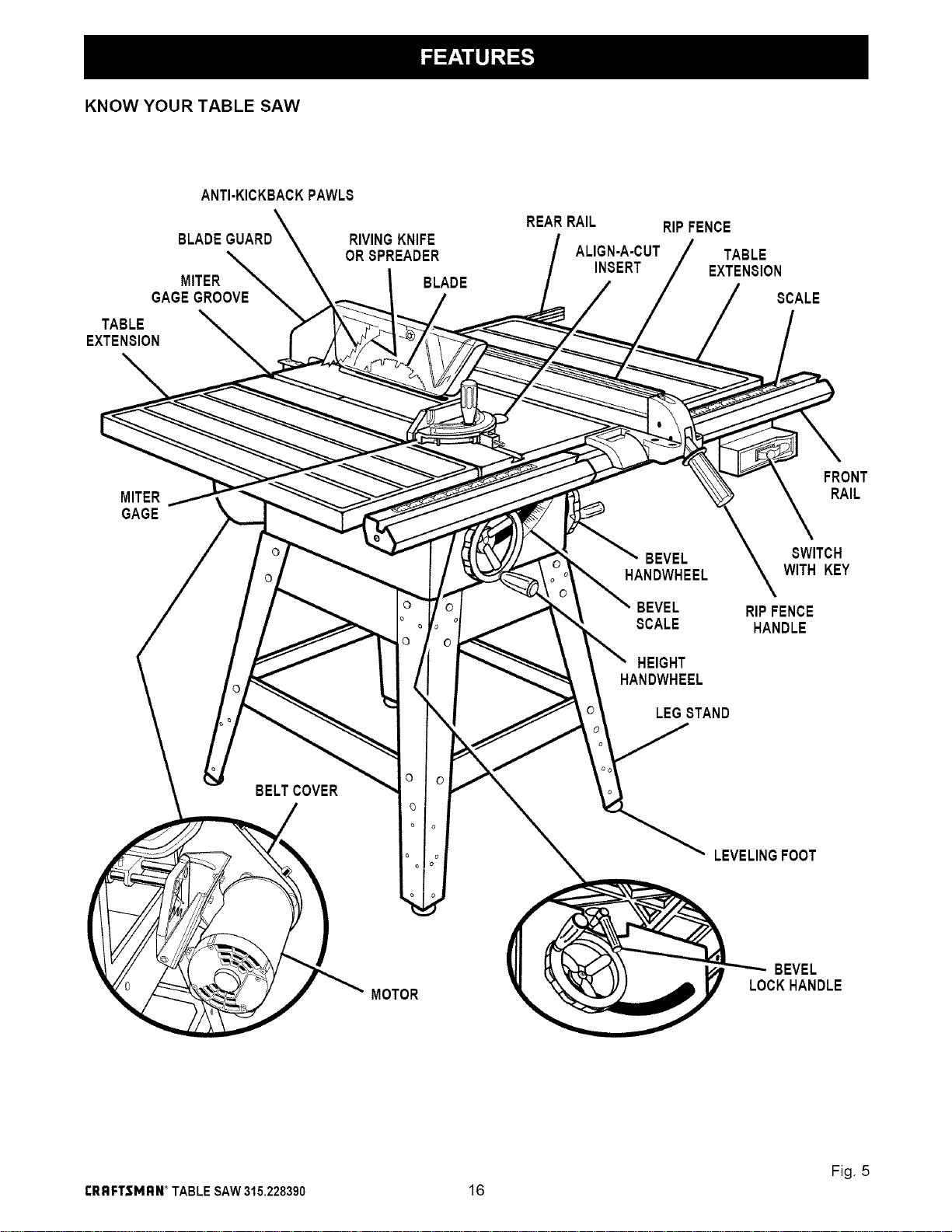
KNOW YOUR TABLE SAW
ANTI-KICKBACKPAWLS
BLADEGUARD
MITER
GAGEGROOVE
TABLE
EXTENSION
RIVINGKNIFE
ORSPREADER
BLADE
REARRAIL
ALIGN-A-CUT
INSERT
RIPFENCE
TABLE
EXTENSION
SCALE
MITER
GAGE
BELTCOVER
BEVEL
HANDWHEEL
BEVEL
SCALE
HEIGHT
HANDWHEEL
LEGSTAND
FRONT
RAIL
SWITCH
WITH KEY
RIPFENCE
HANDLE
LEVELINGFOOT
MOTOR
BEVEL
LOCKHANDLE
Fig. 5
rRRFTSMRN_TABLESAW315.228390 16
OVERVIEW
Theupperportionofthebladeprojectsupthroughthe
table,surroundedbyaninsertcalledthethroatplate,
Theheightofthebladeissetwithahandwheelonthe
frontofthecabinet.Toaccommodatewidepanels,
thetabletophasextensionsoneachside.Detailed
instructionsareprovidedintheOperation section of
this manual for the basic cuts: cross cuts, miter cuts,
bevel cuts, and compound cuts.
For cuts with the blade straight up and cutting across
the grain (cross cuts or miter cuts), use the miter gage
to set the angle and push the wood into the blade, To
cut with the blade straight up, along the grain of the
wood (rip cuts), use the rip fence to guide the wood,
Push smaller pieces with a pushblock or pushstick.
To tilt the blade for a bevel cut, use the bevel
handwheel on the side of the cabinet. A bevel scale
on the front of the cabinet shows the blade angle,
Inside the cabinet, adjustable positive stops control
the degree of tilt,
Use the miter gage with a bevel cross cut (compound
cut) and the rip fence with a bevel rip cut. Other cuts
require special attachments, which have detailed
instructions to reduce risk of injury and ensure the
best performance from your new saw,
Before attempting to use your saw, familiarize yourself
with all operating features and safety requirements of
your Sears Craftsman table saw, The saw's features
are described below,
ALIGN-A-CUT INSERT - A plastic insert on which
marks may be made to indicate the location of the
sawcut on the workpiece,
ANTI-KICKBACK PAWLS - Kickback is a hazard in
which the workpiece is thrown back toward the
operator, The toothed pawls are designed to snag the
workpiece to prevent or reduce injury should kickback
Occur,
BEVEL HANDWHEEL - This handwheel, on the right
side of the cabinet, tilts the blade for a bevel cut.
BEVEL SCALE - The easy-to-read scale on the front
of the workstand shows the exact blade angle,
BLADE -This saw is provided with a Craftsman 64
tooth, 10 in. steel blade. The blade is adjusted with
bevel and height handwheels on the cabinet, Bevel
angles are locked with a handle below the front rail,
,_ WARNING: Be sure to use only blades rated for
at least 5,000 rpm and recommended for use on
this saw. Check with your nearest Sears retail
store.
BLADE GUARD - Always keep the guard down over
the blade for through-sawing cuts.
BEVEL LOCK HANDLE - This handle, placed just
under the worktable surface on the front of the cabi-
net, locks the angle setting of the blade, Be sure the
handle is hanging straight down before tilting the
blade, If it is not straight down, it may jam and bend
the locking bolt,
HEIGHT HANDWHEEL - Use this handwheel to lower
and raise the blade for adjustments or replacement, It
is located on the front of the cabinet.
MITER GAGE - This gage aligns the wood for a
crosscut, The easy-to-read indicator shows the exact
angle for a miter cut, with positive stops at 90 ° and
45 °,
MITER GAGE GROOVES - The miter gage rides in
these grooves on either side of the blade,
MITER GAGE KNOB - Located on the miter gage,
this knob locks in the cutting angle after selection.
MOTOR (13 AMP) - The powerful induction motor is
1,5HP (3HP maximum developed), with capacitor
start and V-belt drive, and is housed in a sturdy steel
base,
RAILS - Front and rear rails provide support for large
workpieces and the rip fence.
RIP FENCE - A sturdy metal fence guides the
workpiece and is secured with the rip fence handle,
Grooves run along the top and sides of the rip fence
for use with optional clamps and accessories,
RIP FENCE HANDLE - The handle on the front of the
rip fence releases the rip fence or locks it in place,
RIVING KNIFE OR SPREADER - Located directly
behind the blade, it keeps cut edges from binding and
supports the blade guard,
SCALE - Found on the front rail, the easy-to-read
scale provides precise measurements in rip cuts,
SWITCH WITH KEY - Your table saw has an easy
access power switch located below the front rail. The
yellow switch key must be removed from the hard-
ware bag and inserted into the switch before saw can
be operated. To lock the switch in the OFF position,
remove the switch key from the switch. Place the key
in a location that is inaccessible to children and others
not qualified to use the tool.
TABLE EXTENSIONS - Removable stamped steel
extensions, 12 in, by 27 in,, support larger work-
pieces,
17 £RRFTSMRW TABLESAW315.228390
Assembly is best done in the area where the saw will be used. When you remove the table saw base, loose
parts, and hardware from the packing materials, check all items with the loose parts list and drawing. If you are
unsure about the description of any part, refer to the drawing. If any parts are missing, delay assembling until
you have obtained the missing part(s).
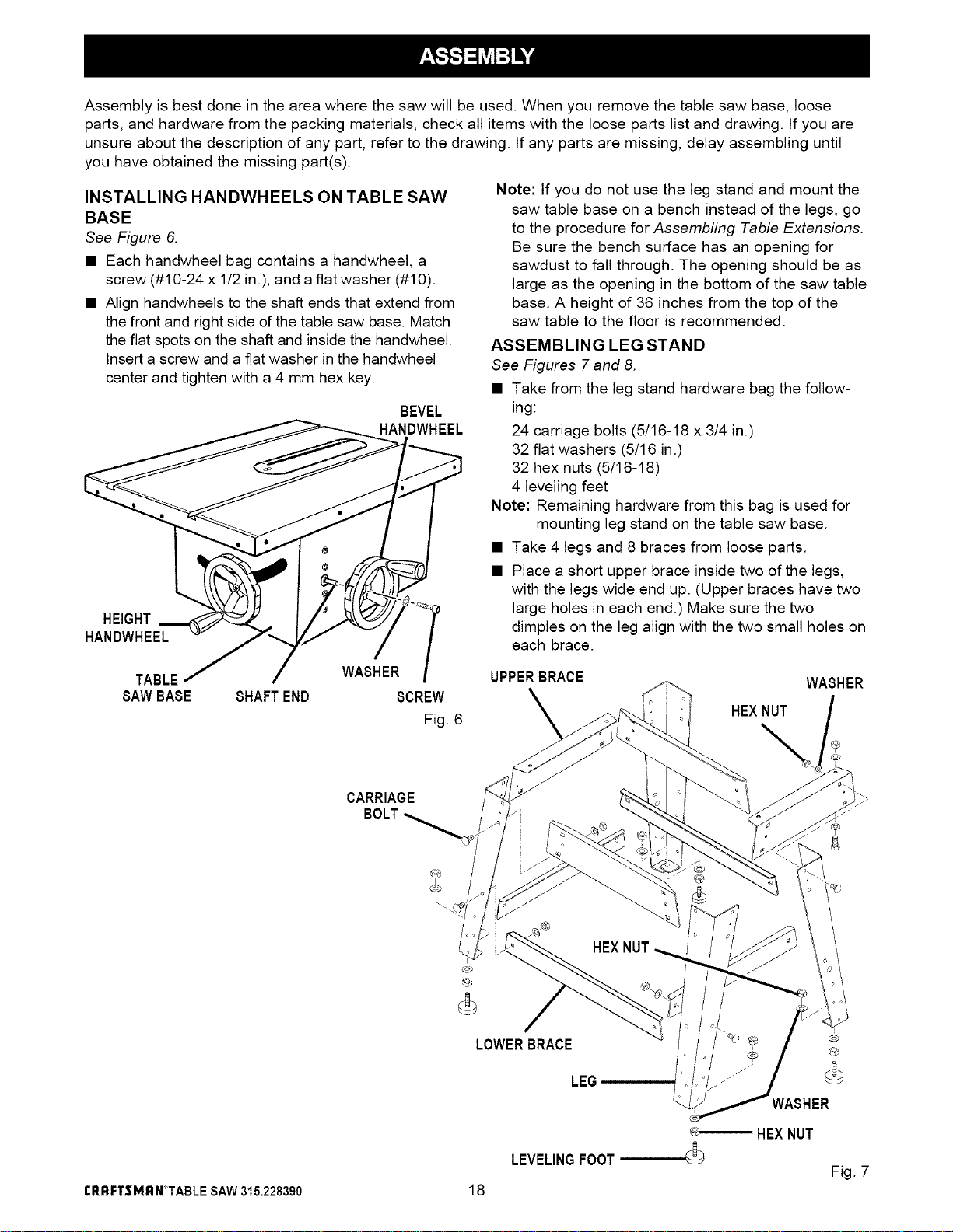
INSTALLING HANDWHEELS ON TABLE SAW
BASE
See Figure 6.
• Each handwheel bag contains a handwheel, a
screw (#10-24 x 1/2 in.), and a flat washer (#10).
• Align handwheels to the shaft ends that extend from
the front and right side of the table saw base. Match
the flat spots on the shaft and inside the handwheel.
Insert a screw and a flat washer in the handwheel
center and tighten with a 4 mm hex key.
HEIGHT
HANDWHEEL
BEVEL
HANDWHEEL
WASHER
TABLE
SAWBASE 8HAFT END 8CREW
Fig. 6
Note: tf you do not use the leg stand and mount the
saw table base on a bench instead of the legs, go
to the procedure for Assembfing Table Extensions.
Be sure the bench surface has an opening for
sawdust to fall through. The opening should be as
large as the opening in the bottom of the saw table
base. A height of 36 inches from the top of the
saw table to the floor is recommended.
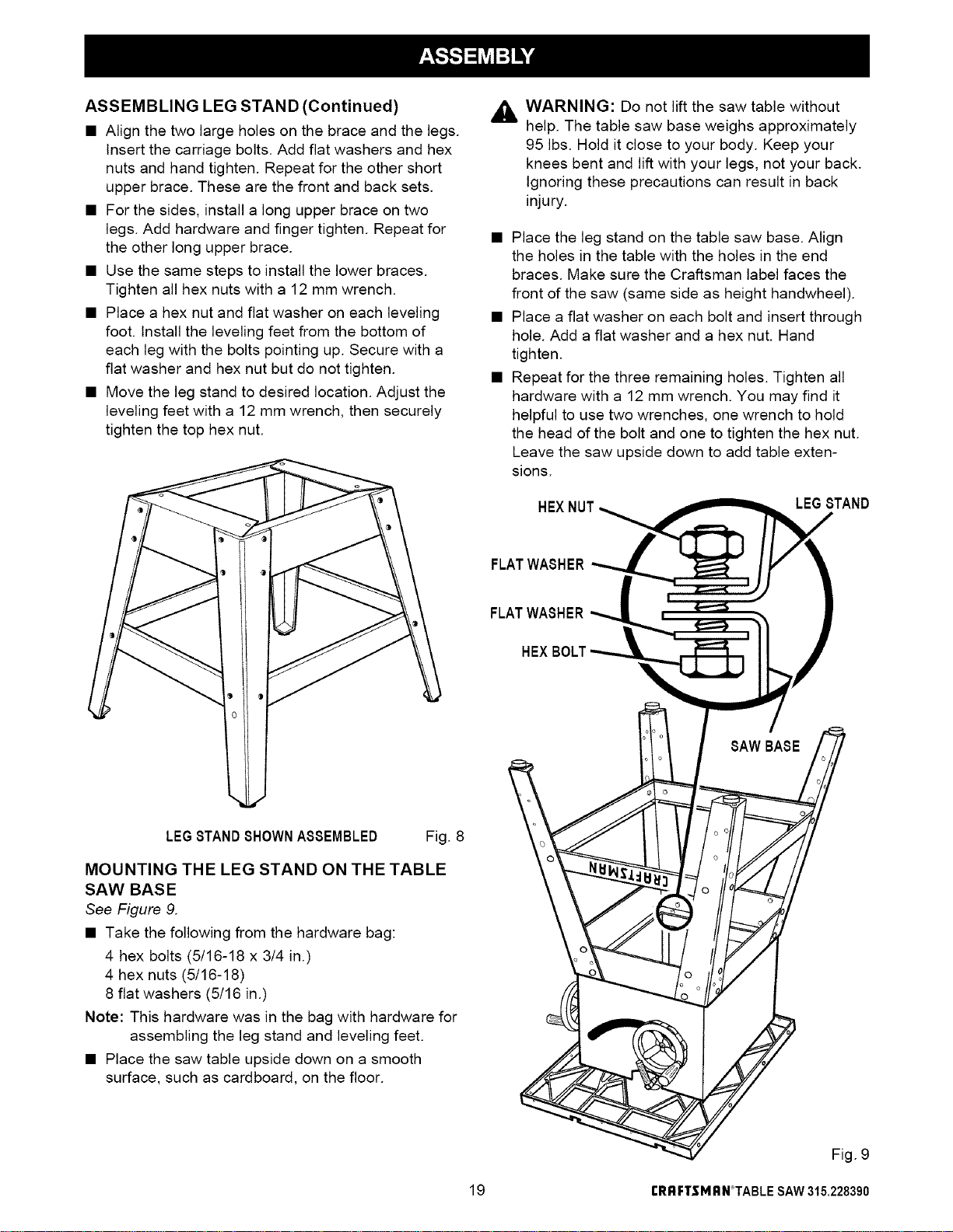
ASSEMBLING LEG STAND
See Figures 7 and 8.
• Take from the leg stand hardware bag the follow-
ing:
24 carriage bolts (5/16-18 x 3/4 in.)
32 flat washers (5/16 in.)
32 hex nuts (5/16-18)
4 leveling feet
Note: Remaining hardware from this bag is used for
mounting leg stand on the table saw base.
• Take 4 legs and 8 braces from loose parts.
• Place a short upper brace inside two of the legs,
with the legs wide end up. (Upper braces have two
large holes in each end.) Make sure the two
dimples on the leg align with the two small holes on
each brace.
UPPERBRACE
WASHER
HEXNUT
CARRIAGE
BOLT
rRRFTSMRN*TABLE SAW315.228390
@
®
LOWERBRACE _#
LEG (_
WASHER
18
HEXNUT
LEVELINGFOOT
Fig. 7
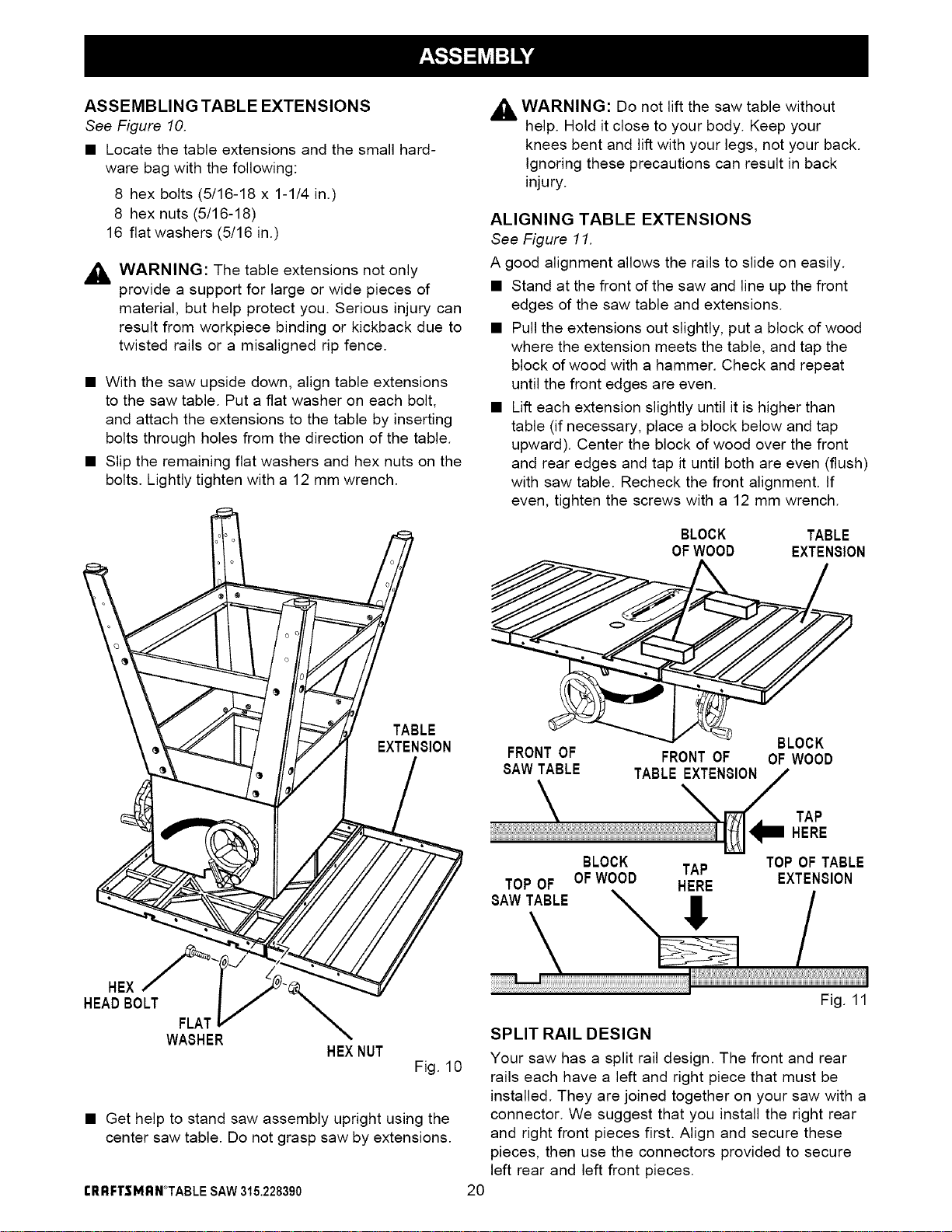
ASSEMBLING LEG STAND (Continued)
• Align the two large holes on the brace and the legs.
Insert the carriage bolts. Add fiat washers and hex
nuts and hand tighten. Repeat for the other short
upper brace. These are the front and back sets.
• For the sides, install a long upper brace on two
legs. Add hardware and finger tighten. Repeat for
the other long upper brace.
• Use the same steps to install the lower braces.
Tighten all hex nuts with a 12 mm wrench.
• Place a hex nut and flat washer on each leveling
foot. Install the leveling feet from the bottom of
each leg with the bolts pointingup. Secure with a
fiat washer and hex nut but do not tighten.
• Move the leg stand to desired location. Adjust the
leveling feet with a 12 mm wrench, then securely
tighten the top hex nut.
,_ WARNING: Do not lift the saw table without
help. The table saw base weighs approximately
95 Ibs. Hold it close to your body. Keep your
knees bent and lift with your legs, not your back.
Ignoring these precautions can result in back
injury.
• Place the leg stand on the table saw base. Align
the holes in the table with the holes in the end
braces. Make sure the Craftsman label faces the
front of the saw (same side as height handwheel).
• Place a flat washer on each bolt and insert through
hole. Add a flat washer and a hex nut. Hand
tighten.
• Repeat for the three remaining holes. Tighten all
hardware with a 12 mm wrench. You may find it
helpful to use two wrenches, one wrench to hold
the head of the bolt and one to tighten the hex nut.
Leave the saw upside down to add table exten-
sions.
LEGSTAND
FLATWASHER
FLATWASHER
LEG8TAND8HOWNA88EMBLED Fig. 8
MOUNTING THE LEG STAND ON THE TABLE
SAW BASE
See Figure 9.
• Take the following from the hardware bag:
4 hex bolts (5/16-18 x 3/4 in.)
4 hex nuts (5/16-18)
8 flat washers (5/16 in.)
Note: This hardware was in the bag with hardware for
assembling the leg stand and leveling feet.
• Place the saw table upside down on a smooth
surface, such as cardboard, on the floor.
19
Fig. 9
rI_RFTSMRN°TABLESAW315.228390
ASSEMBLINGTABLE EXTENSIONS
See Figure 10.
• Locate the tame extensions and the sma(I hard-
ware bag with the following:
8 hex bolts (5/16-18 x 1-1/4 in.'
8 hex nuts (5/16-18)
16 flat washers (5/16 in.)
,_ WARNING: The table extensions not only
provide a support for large or wide pieces of
material, but help protect you. Serious injury can
result from workpiece binding or kickback due to
twisted rails or a misaligned rip fence.
• With the saw upside down, align table extensions
to the saw table. Put a flat washer on each bolt,
and attach the extensions to the table by inserting
bolts through holes from the direction of the table.
• Slip the remaining flat washers and hex nuts on the
bolts. Lightly tighten with a 12 mm wrench.
TABLE
EXTENSION
,_, WARNING: Do not lift the saw table without
u
help. Hold it close to your body. Keep your
knees bent and lift with your legs, not your back.
Ignoring these precautions can result in back
injury.
ALIGNING TABLE EXTENSIONS
See Figure 11.
A good alignment allows the rails to slide on easily.
• Stand at the front of the saw and line up the front
edges of the saw table and extensions.
• Pull the extensions out slightly, put a block of wood
where the extension meets the table, and tap the
block of wood with a hammer. Check and repeat
until the front edges are even.
• Lift each extension slightly until it is higher than
table (if necessary, place a block below and tap
upward). Center the block of wood over the front
and rear edges and tap it until both are even (flush)
with saw table. Recheck the front alignment. If
even, tighten the screws with a 12 mm wrench.
BLOCK
OFWOOD
BLOCK
FRONT OF FRONT OF OF WOOD
SAWTABLE TABLE EXTENSION
TABLE
EXTENSION
TOP OF
SAW TABLE
TAP
HERE
BLOCK TAP TOP OF TABLE
OFWOOD EXTENSION
HERE
!
HEX
HEADBOLT
FLAT
WASHER
HEXNUT
Fig. 10
• Get help to stand saw assembly upright using the
center saw table. Do not grasp saw by extensions.
rRRFTSMRN*TABLE SAW315.228390 2O
Fig. 11
SPLIT RAIL DESIGN
Your saw has a split rail design. The front and rear
rails each have a left and right piece that must be
installed. They are joined together on your saw with a
connector. We suggest that you install the right rear
and right front pieces first. Align and secure these
pieces, then use the connectors provided to secure
left rear and left front pieces.
Note:Therightsideofsawisonyourrightwhen
facingthesaw,asifyouwereinnormal
operatingposition.
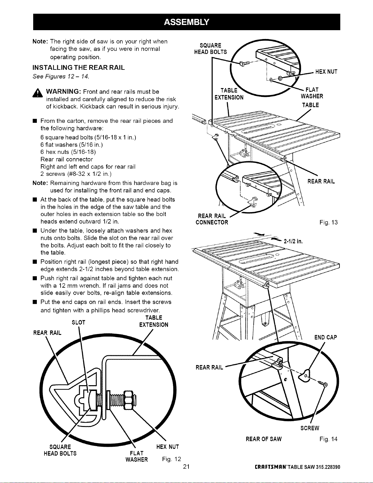
INSTALLINGTHEREARRAIL
See Figures 12- 14.
,4_ WARNING: Front and rear rails must be
installed and carefully aligned to reduce the risk
of kickback. Kickback can result in serious injury.
• From the carton, remove the rear rail pieces and
the following hardware:
6 square head bolts (5/16-18 x 1 in.)
6 fiat washers (5/16 in.)
6 hex nuts (5/16-18)
Rear rail connector
Right and left end caps for rear rail
2 screws (#8-32 x 1/2 in.)
Note: Remaining hardware from this hardware bag is
used for installing the front rail and end caps.
• At the back of the table, put the square head bolts
in the holes in the edge of the saw table and the
outer holes in each extension table so the bolt
heads extend outward 1/2 in.
• Under the table, loosely attach washers and hex
nuts onto bolts. Slide the slot on the rear rail over
the bolts. Adjust each bolt to fit the rail closely to
the table.
• Position right rail (longest piece) so that right hand
edge extends 2-1/2 inches beyond table extension.
• Push right rail against table and tighten each nut
with a 12 mm wrench, tf rail jams and does not
slide easily over bolts, re-align table extensions.
• Put the end caps on rail ends. Insert the screws
and tighten with a phillips head screwdriver.
TABLE
8LOT EXTEN810N
REAR RAIL
8QUARE
WA8HER
TABLE
REARRAIL
REARRAIL
CONNECTOR
Fig. 13
2-1/2in,
ENDCAP
REARRAIL
8QUARE HEXNUT
HEADBOLT8 FLAT
WA8HER Fig. 12
21
REAROF8AW
8CREW
Fig. 14
rRRFTSMRN°TABLE SAW315.228390
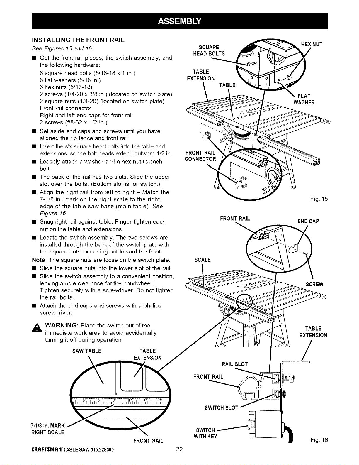
INSTALLING THE FRONT RAIL
See Figures 15 and 16.
• Get the front rail pieces, the switch assembly, and
the following hardware:
6 square head bolts (5/16-18 x 1 in.)
6 flat washers (5/16 in.)
6 hex nuts (5/16-18)
2 screws (1/4-20 x 3/8 in.) (located on switch plate)
2 square nuts (1/4-20) (located on switch plate)
Front rail connector
Right and left end caps for front rail
2 screws (#8-32 x 1/2 in.)
• Set aside end caps and screws until you have
aligned the rip fence and front rail.
• Insert the six square head bolts into the table and
extensions, so the bolt heads extend outward 1/2 in.
• Loosely attach a washer and a hex nut to each
bolt.
• The back of the rail has two slots. Slide the upper
slot over the bolts. (Bottom slot is for switch.)
• Align the right rail from left to right - Match the
7-1/8 in. mark on the right scale to the right
edge of the table saw base (main table). See
Figure 16.
• Snug right rail against table. Finger-tighten each
nut on the table and extensions.
• Locate the switch assembly. The two screws are
installed through the back of the switch plate with
the square nuts extending out toward the front.
Note: The square nuts are loose on the switch plate.
• Slide the square nuts into the lower slot of the rail.
• Slide the switch assembly to a convenient position,
leaving ample clearance for the handwhee].
Tighten securely with a screwdriver. Do not tighten
the rail bolts.
• Attach the end caps and screws with a phillips
screwdriver.
,_ WARNING: Place the switch out of the
immediate work area to avoid accidentally
turning it off during operation.
SAWTABLE TABLE
EXTENSION
8"UARE _ _HEX NUT
HE_ BOLT8
__ _'_-.._ WASHER
FRONT RAIL_/_ _ -_
CONNECTOR
_ %,_,,,,,,_,,,__ \_,_ <_. r _ Fig. 15
FRONTRAIL
ENDCAP
SCALE
8CREW
TABLE
EXTENSION
RAIL 8LOT
FRONTRAIL
7-118in, MARK
RIGHTSCALE
FRONTRAIL
8WITCH
WITHKEY
Fig. 16
rRI;IFTSMRN*TABLE SAW315.228390 22
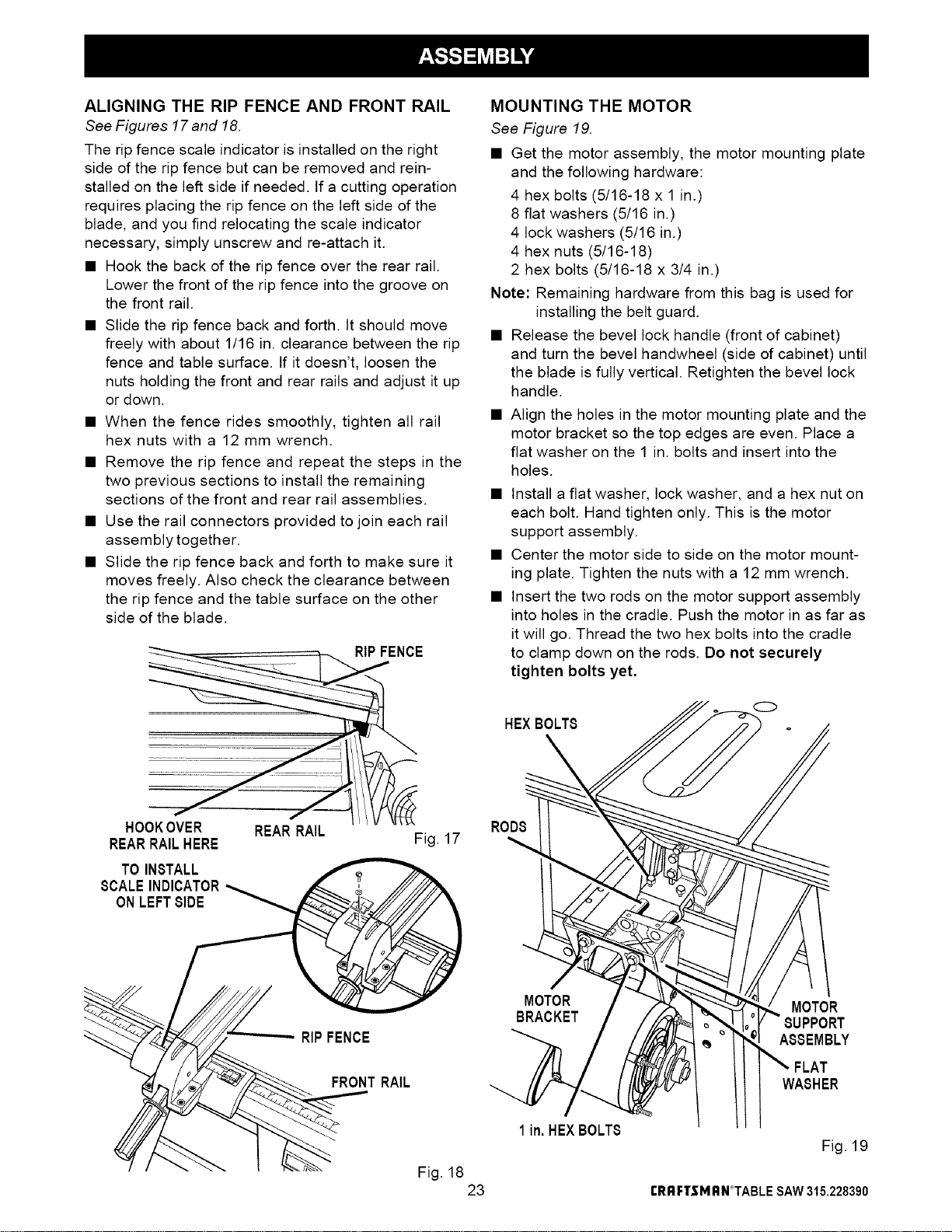
ALIGNING THE RIP FENCE AND FRONT RAIL
See Figures 17 and 18.
The rip fence scale indicator is installed on the right
side of the rip fence but can be removed and rein-
stalled on the left side if needed, tf a cutting operation
requires placing the rip fence on the left side of the
blade, and you find relocating the scale indicator
necessary, simply unscrew and re-attach it.
• Hook the back of the rip fence over the rear rail.
Lower the front of the rip fence into the groove on
the front rail.
• Slide the rip fence back and forth, tt should move
freely with about 1/16 in. clearance between the rip
fence and table surface. If it doesn't, loosen the
nuts holding the front and rear rails and adjust it up
or down.
• When the fence rides smoothly, tighten all rail
hex nuts with a 12 mm wrench.
• Remove the rip fence and repeat the steps in the
two previous sections to install the remaining
sections of the front and rear rail assemblies.
• Use the rail connectors provided to join each rail
assembly together.
• Slide the rip fence back and forth to make sure it
moves freely. Also check the clearance between
the rip fence and the table surface on the other
side of the blade.
HOOKOVER REAR RAIL
REARRAILHERE
TO INSTALL
SCALEINDICATOR
ONLEFTBIDE
RIPFENCE
Fig. 17
MOUNTING THE MOTOR
See Figure 19.
• Get the motor assembly, the motor mounting plate
and the following hardware:
4 hex bolts (5/16-18 x 1 in.)
8 fiat washers (5/16 in.)
4 lock washers (5/16 in.)
4 hex nuts (5/16-18)
2 hex bolts (5/16-18 x 3/4 in.)
Note: Remaining hardware from this bag is used for
installing the belt guard.
• Release the bevel lock handle (front of cabinet)
and turn the bevel handwheel (side of cabinet) until
the blade is fully vertical. Retighten the bevel lock
handle.
• Align the holes in the motor mounting plate and the
motor bracket so the top edges are even. Place a
fiat washer on the 1 in. bolts and insert into the
holes.
• Install a fiat washer, lock washer, and a hex nut on
each bolt. Hand tighten only. This is the motor
support assembly.
• Center the motor side to side on the motor mount-
ing plate. Tighten the nuts with a 12 mm wrench.
• Insert the two rods on the motor support assembly
into holes in the cradle. Push the motor in as far as
it will go. Thread the two hex bolts into the cradle
to clamp down on the rods. Do not securely
tighten bolts yet.
HEXBOLTS
0
RODS
RIPFENCE
MOTOR
BRACKET
MOTOR
SUPPORT
ASSEMBLY
FRONTRAIL
Fig. 18
23
1in. HEXBOLTS
WASHER
Fig. 19
rRRFTSMRN°TABLE SAW315.228390
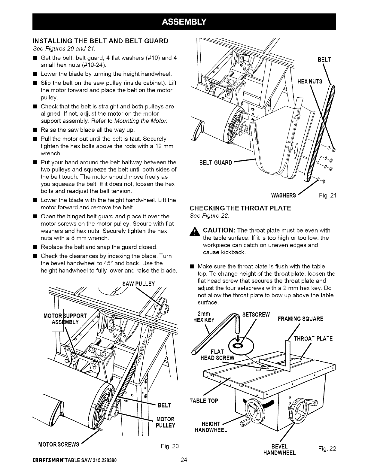
INSTALLING THE BELT AND BELT GUARD
See Figures 20 and 21.
• Get the belt, belt guard, 4 flat washers (#10) and 4
small hex nuts (#10-24).
• Lower the blade by turning the height handwheel.
• Slip the belt on the saw pulley (inside cabinet). Lift
the motor forward and place the belt on the motor
pulley.
• Check that the belt is straight and both pulleys are
aligned. If not, adjust the motor on the motor
support assembly. Refer to Mounting the Motor.
• Raise the saw blade all the way up.
• Pull the motor out until the belt is taut. Securely
tighten the hex bolts above the rods with a 12 mm
wrench.
• Put your hand around the belt halfway between the
two pulleys and squeeze the belt until both sides of
the belt touch. The motor should move freely as
you squeeze the belt. If it does not, loosen the hex
bolts and readjust the belt tension.
• Lower the blade with the height handwheel. Lift the
motor forward and remove the belt.
• Open the hinged belt guard and place it over the
motor screws on the motor pulley. Secure with flat
washers and hex nuts. Securely tighten the hex
nuts with a 8 mm wrench.
• Replace the belt and snap the guard closed.
• Check the clearances by indexing the blade. Turn
the bevel handwheel to 45 ° and back. Use the
height handwheel to fully lower and raise the blade.
SAWPULLEY
BELT
BELTGUARD
WASHER_
CHECKING THE THROAT PLATE
See Figure 22.
Fig. 21
,_ CAUTION: The throat plate must be even with
the table surface. If it is too high or too low, the
workpiece can catch on uneven edges and
cause kickback.
Make sure the throat plate is flush with the table
top. To change height of the throat plate, loosen the
flat head screw that secures the throat plate and
adjust the four setscrews with a 2 mm hex key. Do
not allow the throat plate to bow up above the table
surface.
2mm SETSCREW
HEXKEY FRAMINGSQUARE
THROATPLATE
HEADSCREW
MOTORSCREW8
CRRFTSMRN_TABLESAW315.228390
BELT
MOTOR
PULLEY
Fig. 20
TABLETOP
HEIGHT
HANDWHEEL
24
BEVEL
HANDWHEEL
Fig. 22
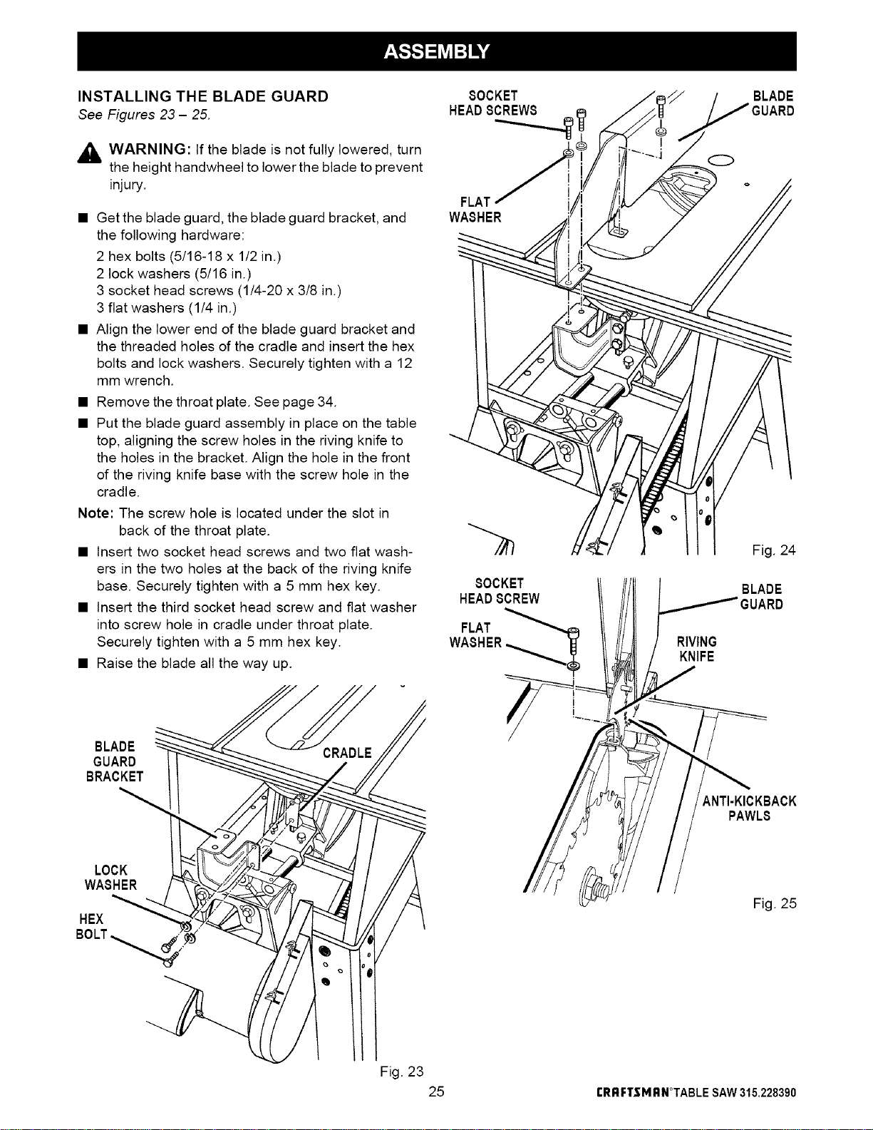
INSTALLING THE BLADE GUARD
See Figures 23- 25.
_k WARNING: If the blade is not fully lowered, turn
the height handwheel to lower the blade to prevent
injury
• Get the blade guard, the blade guard bracket, and
the following hardware:
2 hex bolts (5/16-18 x 1/2 in.)
2 lock washers (5/16 in.)
3 socket head screws (1/4-20 x 3/8 in.)
3 flat washers (1/4 in.)
• Align the lower end of the blade guard bracket and
the threaded holes of the cradle and insert the hex
bolts and lock washers. Securely tighten with a 12
mm wrench.
• Remove the throat plate. See page 34.
• Put the blade guard assembly in place on the table
top, aligning the screw holes in the riving knife to
the holes in the bracket. Align the hole in the front
of the riving knife base with the screw hole in the
cradle.
Note: The screw hole is located under the slot in
back of the throat plate.
• Insert two socket head screws and two flat wash-
ers in the two holes at the back of the riving knife
base. Securely tighten with a 5 mm hex key.
• Insert the third socket head screw and flat washer
into screw hole in cradle under throat plate.
Securely tighten with a 5 mm hex key.
• Raise the blade all the way up.
8OCKET
HEAD8CREW8
FLAT
WASHER
8OCKET
HEAD8CREW
FLAT
WASHER
O
RIVING
KNIFE
BLADE
Fig. 24
BLADE
BLADE
GUARD
BRACKET
ANTI-KICKBACK
PAWLS
LOCK
WASHER
HEX
BOLT_.
Fig. 25
Fig. 23
25 rRRFTSMRN°TABLESAW315.228390
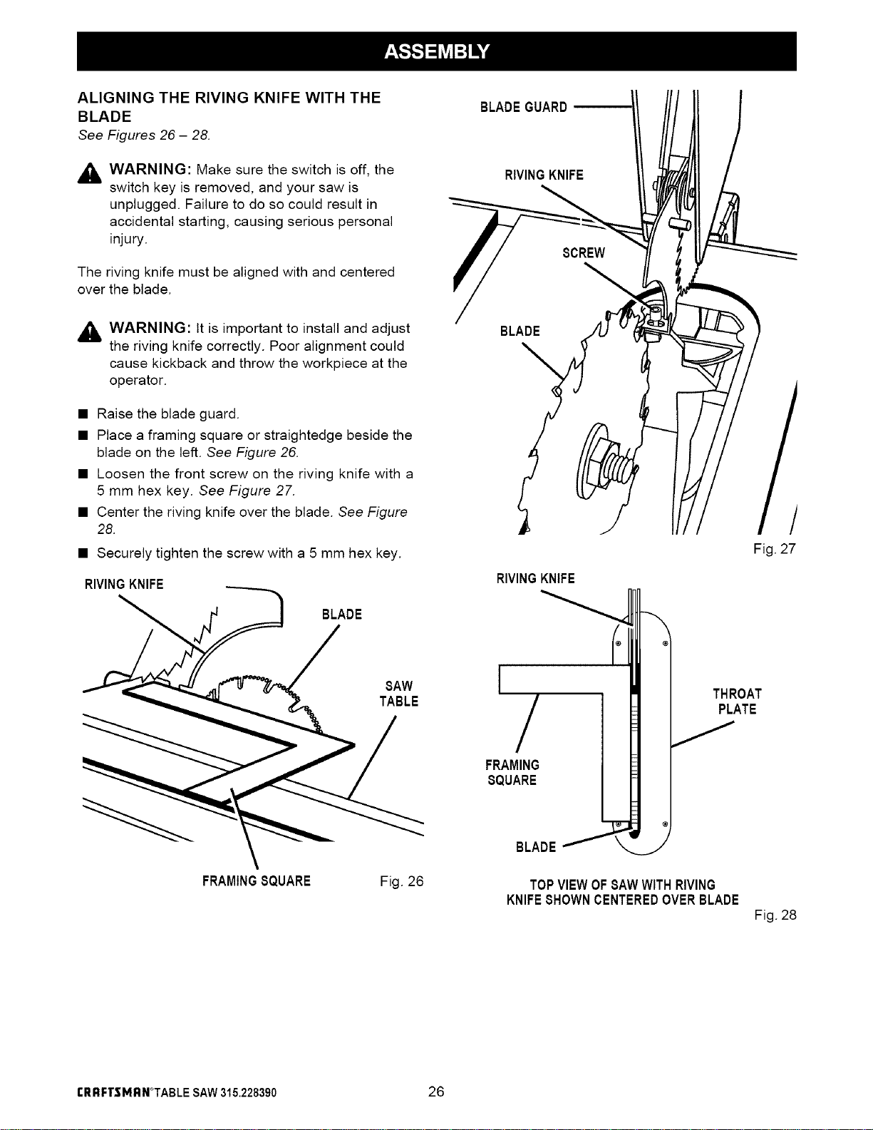
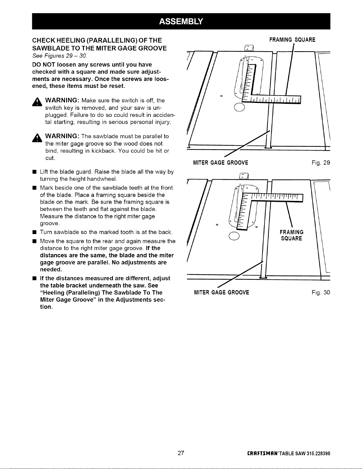
ALIGNINGTHE RIVING KNIFE WITH THE
BLADE
See Figures 26 - 28.
_i WARNING: Make sure the switch is off, the
switch key is removed, and your saw is
unplugged. Failure to do so could result in
accidental starting, causing serious personal
injury.
The riving knife must be aligned with and centered
over the blade.
_i WARNING: It is important to install and adjust
the riving knife correctly. Poor alignment could
cause kickback and throw the workpiece at the
operator.
• Raise the blade guard.
• Place a framing square or straightedge beside the
blade on the left. See Figure 26.
• Loosen the front screw on the riving knife with a
5 mm hex key. See Figure 27.
• Center the riving knife over the blade. See Figure
28.
• Securely tighten the screw with a 5 mm hex key.
RIVINGKNIFE
BLADE
SAW
TABLE
FRAMINGSQUARE Fig. 26
BLADE GUARD
RIVINGKNIFE
BLADE
RIVINGKNIFE
'/
FRAMING
SQUARE
BLADE_
J
THROAT
PLATE
TOPVIEWOFSAWWITHRIVING
KNIFESHOWNCENTEREDOVERBLADE
/
Fig. 27
Fig. 28
rRRFTSMRN*TABLE SAW315.228390 26
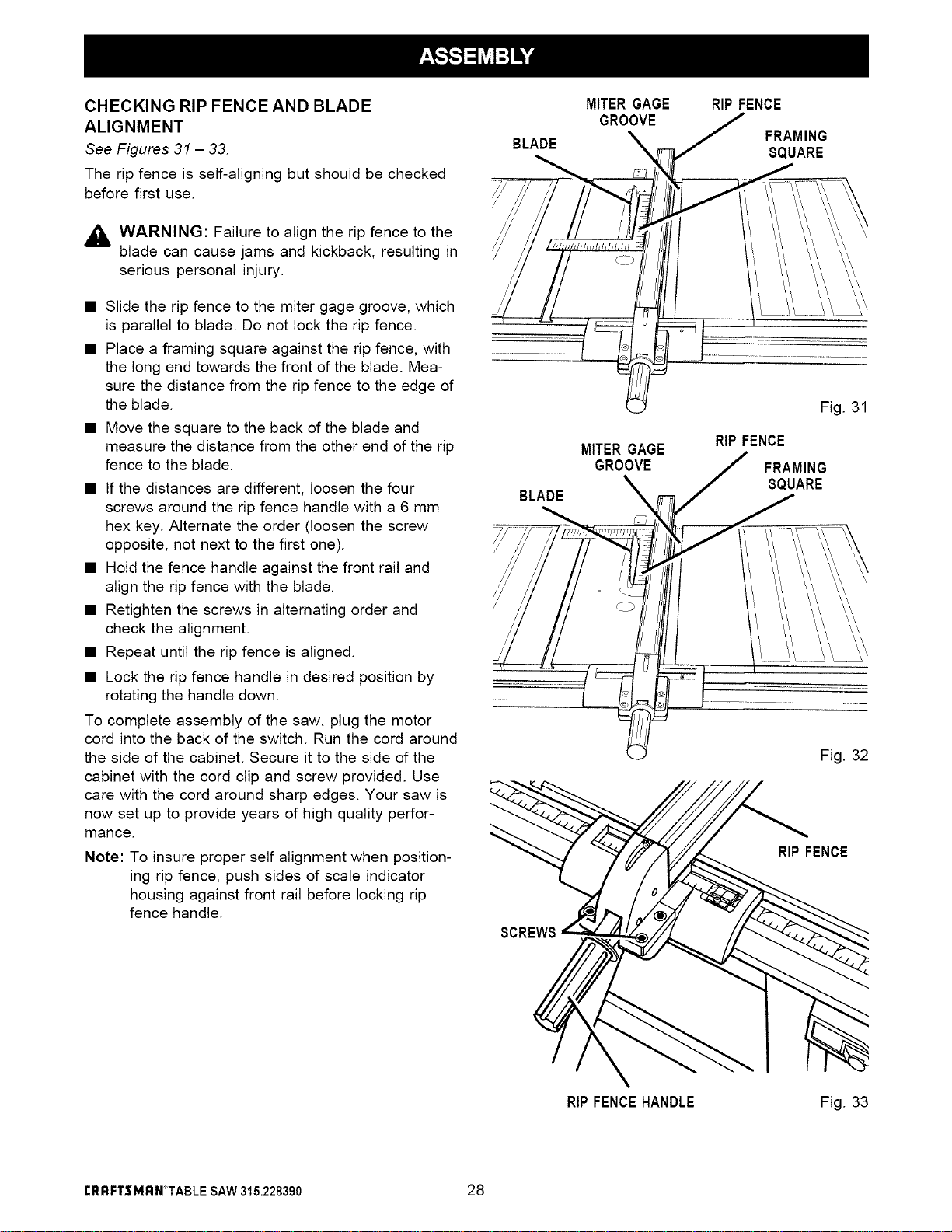
CHECK HEELING (PARALLELING) OF THE
SAWBLADE TO THE MITER GAGE GROOVE
See Figures 29 - 30.
DO NOT loosen any screws until you have
checked with a square and made sure adjust-
ments are necessary. Once the screws are loos-
ened, these items must be reset.
_k WARNING: Make sure the switch is off, the
switch key is removed, and your saw is un-
plugged. Failure to do so could result in acciden-
tal starting, resulting in serious personal injury.
_ WARNING: The sawblade must be parallel to
the miter gage groove so the wood does not
bind, resulting in kickback. You could be hit or
cut.
• Lift the blade guard. Raise the blade all the way by
turning the height handwheel.
• Mark beside one of the sawblade teeth at the front
of the blade. Place a framing square beside the
blade on the mark. Be sure the framing square is
between the teeth and fiat against the blade.
Measure the distance to the right miter gage
groove.
• Turn sawblade so the marked tooth is at the back.
• Move the square to the rear and again measure the
distance to the right miter gage groove. If the
distances are the same, the blade and the miter
gage groove are parallel. No adjustments are
needed.
• If the distances measured are different, adjust
the table bracket underneath the saw. See
"Heeling (Paralleling) The Sawblade To The
Miter Gage Groove" in the Adjustments sec-
tion.
I_llll
Q
MITERGAGEGROOVE
FRAMINGSQUARE
1/'
Jt*l lfllll
Fig. 29
MITERGAGEGROOVE
Fig. 30
27 rRRFTSMRN°TABLE SAW315.228390
CHECKING RIP FENCE AND BLADE
ALIGNMENT
See Figures 31 - 33.
The rip fence is self-a(igning but should be checked
before first use.
,_ WARNING: Failure to align the rip fence to the
blade can cause jams and kickback, resulting in
serious personal injury.
• Slide the rip fence to the miter gage groove, which
is parallel to blade. Do not lock the rip fence.
• Place a framing square against the rip fence, with
the long end towards the front of the blade. Mea-
sure the distance from the rip fence to the edge of
the blade.
• Move the square to the back of the blade and
measure the distance from the other end of the rip
fence to the blade.
• If the distances are different, loosen the four
screws around the rip fence handle with a 6 mm
hex key. Alternate the order (loosen the screw
opposite, not next to the first one).
• Hold the fence handle against the front rail and
align the rip fence with the blade.
• Retighten the screws in alternating order and
check the alignment.
• Repeat until the rip fence is aligned.
• Lock the rip fence handle in desired position by
rotating the handle down.
To complete assembly of the saw, plug the motor
cord into the back of the switch. Run the cord around
the side of the cabinet. Secure it to the side of the
cabinet with the cord clip and screw provided. Use
care with the cord around sharp edges. Your saw is
now set up to provide years of high quality perfor-
mance.
Note: To insure proper self alignment when position-
ing rip fence, push sides of scale indicator
housing against front rail before locking rip
fence handle.
BLADE
BLADE
8CREW8
MITER GAGE
GROOVE
MITER GAGE
GROOVE
RIP FENCE
FRAMING
SQUARE
Fig. 31
RIP FENCE
FRAMING
SQUARE
Fig. 32
RIP FENCE
RIP FENCEHANDLE
Fig. 33
rRRFTSMRN*TABLE SAW315.228390 28
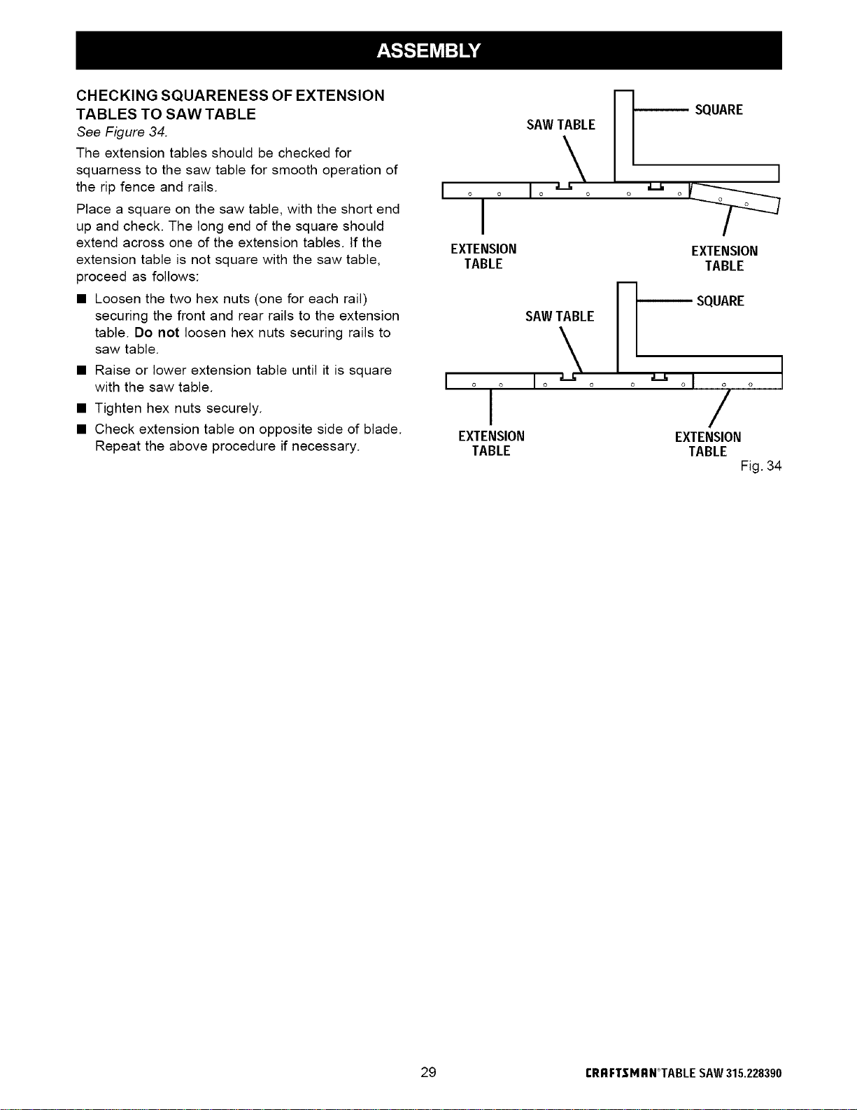
CHECKING SQUARENESS OF EXTENSION
TABLES TO SAW TABLE
See Figure 34.
The extension tables should be checked for
squarness to the saw table for smooth operation of
the rip fence and rails.
Place a square on the saw table, with the short end
up and check. The long end of the square should
extend across one of the extension tables. If the
extension table is not square with the saw table,
proceed as follows:
• Loosen the two hex nuts (one for each rail)
securing the front and rear rails to the extension
table. Do not loosen hex nuts securing rails to
saw table.
• Raise or lower extension table until it is square
with the saw table.
• Tighten hex nuts securely.
• Check extension table on opposite side of blade.
Repeat the above procedure if necessary.
I o
SAWTABLE
Io o
SQUARE
EXTENSION
TABLE
I
o o
EXTENSION
TABLE
SAWTABLE
o o Io o o
I
EXTENSION
TABLE
a L
SQUARE
o,/o
EXTENSION
TABLE
Fig. 34
29 rRRFTgMRN°TABLE SAW315.228390

To avoid unnecessary setups and adjustments, a
good practice is to check your setups carefully with a
framing square and make practice cuts in scrap wood
before making finish cuts in good workpieces. Do not
start any adjustments until you have checked with a
square and made test cuts to be sure adjustments
are needed.
REPLACING THE BLADE
See Figures 35- 37.
_ WARNING: Make sure the switch is off, the
switch key is removed, and your saw is
unplugged. Failure to do so could result in
accidental starting, resulting in serious personal
injury.
TO LOOSEN
BLADENUT
BLADE
GUARD
BLADE
NUT
• Raise the blade guard and remove the throat plate.
To remove, loosen the screw at the front with a
phillips screwdriver and lift the front end. Pull it out
toward the front end.
• Raise the blade to its highest position by turning
the height handwheel clockwise. Angle the blade
straight up by loosening the bevel lock handle and
turning the bevel handwheel. Wedge a piece of
scrap wood against the front of the blade. See
Figure 35.
• Loosen the blade nut with the blade wrench
provided with your saw. Remove the blade nut and
blade washer. Carefully remove the scrap wood
and blade.
• To replace the blade with an accessory blade,
follow the instructions provided with the accessory.
• To install a standard blade, place the new blade on
the arbor shaft, with teeth pointing down toward the
front of the saw. Wedge a piece of scrap wood at
the back of the blade. See Figure 37.
_k CAUTION: The teeth must point down toward
the front of the saw to work properly. Otherwise,
damage to the blade, saw, or workpiece can
OCCUr.
SCRAPWOOD
.BLADE
WASHER
Fig. 35
_/_ BLADE
BLA__I WASHER
//_ULADE NUT
• Place the blade washer and the blade nut over the
blade arbor. Be sure the dome side of the blade
washer faces out from the blade and that all items
are snug against the arbor housing. Tighten se-
curely.
• Remove the scrap wood and rotate the blade by
hand to make sure it turns freely.
• Slip the throat plate into the opening and push it
toward the back of the saw to engage the spring
clip. Securely tighten the screw. If the throat plate
is not flush with the table, adjust the setscrews with
a 2 mm hex key. Do not allow the throat plate to
bow up above the table surface.
ARBORBHAFT
/
Fig. 36
{:RRFTBMI_N_TABLESAW315.228390 30
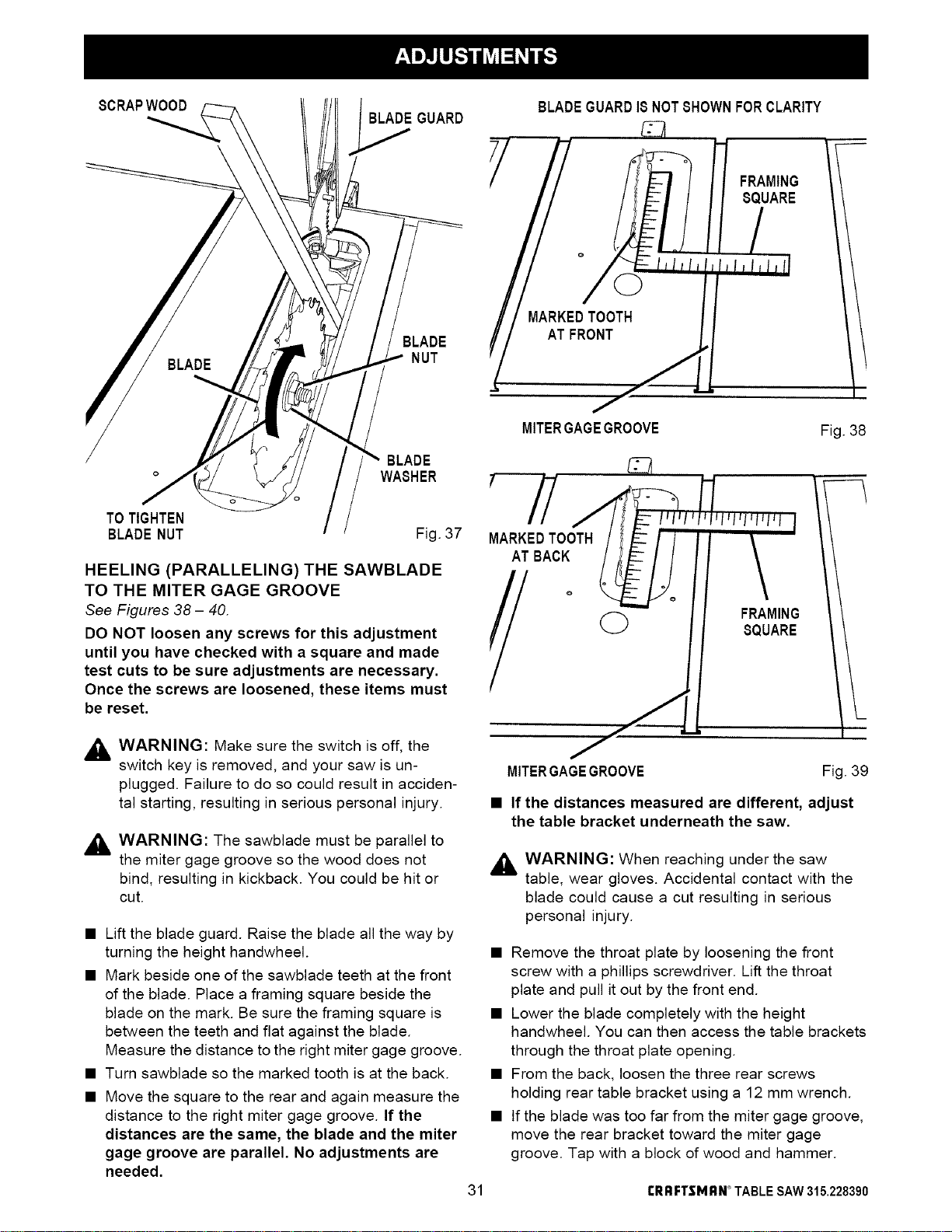
8CRAPWOOD
BLADEGUARD
BLADE
NUT
BLADEGUARD18NOTSHOWNFORCLARITY
I MARKEDTOOTH
AT FRONT
__
FRAMING
SQUARE
BLADE
WASHER
TOTIGHTEN
BLADENUT Fig. 37
HEELING (PARALLELING) THE SAWBLADE
TO THE MITER GAGE GROOVE
See Figures 38- 40.
DO NOT loosen any screws for this adjustment
until you have checked with a square and made
test cuts to be sure adjustments are necessary.
Once the screws are loosened, these items must
be reset.
,_ WARNING: Make sure the switch is off, the
switch key is removed, and your saw is un-
plugged. Failure to do so could result in acciden-
tal starting, resulting in serious personal injury.
_, WARNING: The sawblade must be parallel to
the miter gage groove so the wood does not
bind, resulting in kickback. You could be hit or
cut.
• Lift the blade guard. Raise the blade all the way by
turning the height handwheel.
• Mark beside one of the sawblade teeth at the front
of the blade. Place a framing square beside the
blade on the mark. Be sure the framing square is
between the teeth and flat against the blade.
Measure the distance to the right miter gage groove.
• Turn sawblade so the marked tooth is at the back.
• Move the square to the rear and again measure the
distance to the right miter gage groove. If the
distances are the same, the blade and the miter
gage groove are parallel. No adjustments are
needed.
MITERGAGEGROOVE Fig. 38
C33
MARKEDTOOTH
AT BACK
G FRAMING
SQUARE
31
MITERGAGEGROOVE Fig. 39
• If the distances measured are different, adjust
the table bracket underneath the saw.
_lb WARNING: When reaching under the saw
table, wear gloves. Accidental contact with the
blade could cause a cut resulting in serious
personal injury.
• Remove the throat plate by loosening the front
screw with a phillips screwdriver. Lift the throat
plate and pull it out by the front end.
• Lower the blade completely with the height
handwheel. You can then access the table brackets
through the throat plate opening.
• From the back, loosen the three rear screws
holding rear table bracket using a 12 mm wrench.
• If the blade was too far from the miter gage groove,
move the rear bracket toward the miter gage
groove. Tap with a block of wood and hammer.
CI_RFTSMRN_TABLESAW315.228390
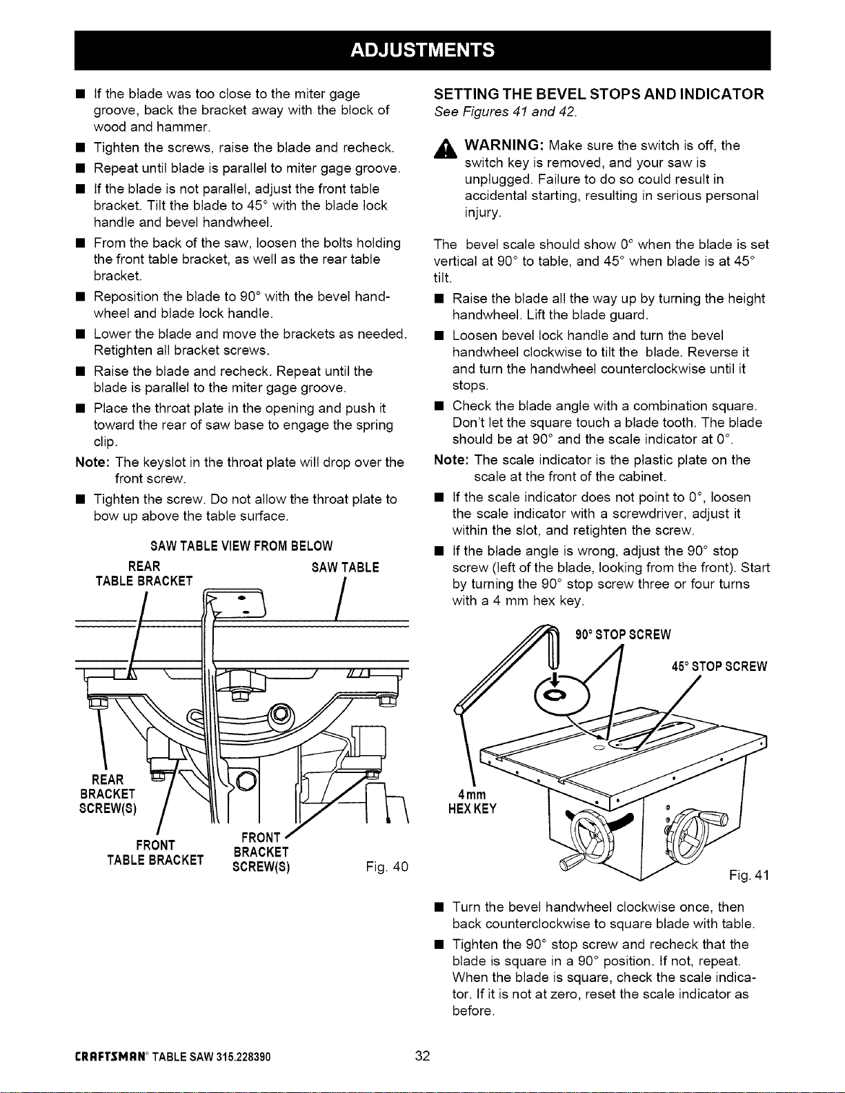
• If the blade was too close to the miter gage
groove, back the bracket away with the block of
wood and hammer.
• Tighten the screws, raise the blade and recheck.
• Repeat until blade is parallel to miter gage groove.
• If the blade is not parallel, adjust the front table
bracket. Tilt the blade to 45 ° with the blade lock
handle and bevel handwheel.
• From the back of the saw, loosen the bolts holding
the front table bracket, as well as the rear table
bracket.
• Reposition the blade to 90° with the bevel hand-
wheel and blade lock handle.
• Lower the blade and move the brackets as needed.
Retighten all bracket screws.
• Raise the blade and recheck. Repeat until the
blade is parallel to the miter gage groove.
• Place the throat plate in the opening and push it
toward the rear of saw base to engage the spring
clip.
Note: The keyslot in the throat plate will drop over the
front screw.
• Tighten the screw. Do not allow the throat plate to
bow up above the table surface.
SAWTABLEVIEWFROMBELOW
REAR
TABLEBRACKET
FRONTj
FRONT BRACKET
TABLEBRACKET SCREW(S)
SAWTABLE
/
Fig. 40
SETTING THE BEVEL STOPS AND INDICATOR
See Figures 41 and 42.
_ WARNING: Make sure the switch is off, the
switch key is removed, and your saw is
unplugged. Failure to do so could result in
accidental starting, resulting in serious personal
injury.
The bevel scale should show 0° when the blade is set
vertical at 90° to table, and 45° when blade is at 45 °
tilt.
• Raise the blade all the way up by turning the height
handwheel. Lift the blade guard.
• Loosen bevel lock handle and turn the bevel
handwheel clockwise to tilt the blade. Reverse it
and turn the handwheel counterclockwise until it
stops.
• Check the blade angle with a combination square.
Don't let the square touch a blade tooth. The blade
should be at 90 ° and the scale indicator at 0°.
Note: The scale indicator is the plastic plate on the
scale at the front of the cabinet.
• If the scale indicator does not point to 0°, loosen
the scale indicator with a screwdriver, adjust it
within the slot, and retighten the screw.
• If the blade angle is wrong, adjust the 90° stop
screw (left of the blade, looking from the front). Start
by turning the 90° stop screw three or four turns
with a 4 mm hex key.
90oSTOPSCREW
45oSTOPSCREW
4mm
HEXKEY
Fig. 41
• Turn the bevel handwheel clockwise once, then
back counterclockwise to square blade with table.
• Tighten the 90° stop screw and recheck that the
blade is square in a 90° position. If not, repeat.
When the blade is square, check the scale indica-
tor. tf it is not at zero, reset the scale indicator as
before.
CRRFTSMI_N° TABLESAW315.228390 32
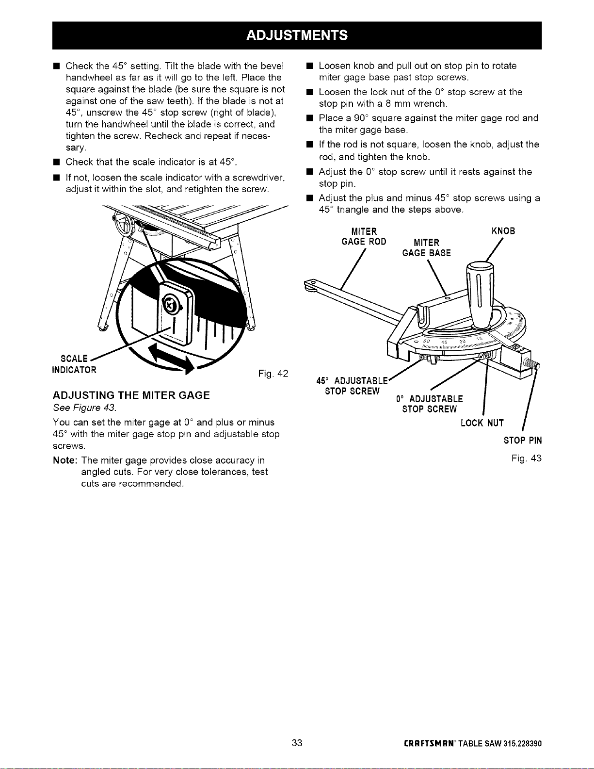
• Check the 45 ° setting. Tilt the blade with the bevel
handwheel as far as it will go to the left. Place the
square against the blade (be sure the square is not
against one of the saw teeth). If the blade is not at
45 °, unscrew the 45 ° stop screw (right of blade),
turn the handwheel until the blade is correct, and
tighten the screw. Recheck and repeat if neces-
sary.
• Check that the scale indicator is at 45 °.
• If not, loosen the scale indicator with a screwdriver,
adjust it within the slot, and retighten the screw.
8CALE
INDICATOR
Fig. 42
ADJUSTING THE MITER GAGE
See Figure 43.
You can set the miter gage at 0° and plus or minus
45° with the miter gage stop pin and adjustable stop
screws.
Note: The miter gage provides close accuracy in
angled cuts. For very close tolerances, test
cuts are recommended.
• Loosen knob and pull out on stop pin to rotate
miter gage base past stop screws.
• Loosen the lock nut of the 0° stop screw at the
stop pin with a 8 mm wrench.
• Place a 90° square against the miter gage rod and
the miter gage base.
• If the rod is not square, loosen the knob, adjust the
rod, and tighten the knob.
• Adjust the 0° stop screw until it rests against the
stop pin.
• Adjust the plus and minus 45 ° stop screws using a
45 ° triangle and the steps above.
MITER
GAGEROD MITER
8TOP 8CREW "
0° ADJUSTABLE
8TOP 8CREW
LOCK
KNOB
/
N
8TOP PiN
Fig. 43
33 I:I_I;IFTSMI;IN_TABLESAW315.228390
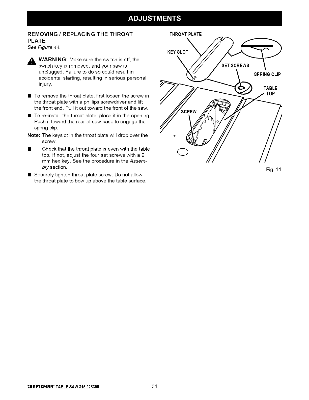
REMOVING / REPLACING THE THROAT
PLATE
See Figure 44.
,_k WARNING: Make sure the switch is off, the
switch key is removed, and your saw is
unplugged. Failure to do so could result in
accidental starting, resulting in serious personal
injury.
• To remove the throat plate, first loosen the screw in
the throat plate with a phillips screwdriver and lift
the front end. Pull it out toward the front of the saw.
• To re-install the throat plate, place it in the opening.
Push it toward the rear of saw base to engage the
spring clip.
Note: The keyslot in the throat plate will drop over the
screw.
• Check that the throat plate is even with the table
top. If not, adjust the four set screws with a 2
mm hex key. See the procedure in the Assem-
bly section.
• Securely tighten throat plate screw. Do not allow
the throat plate to bow up above the table surface.
THROATPLATE
KEY 8LOT_
SPRINGCLIP
TABLE
TOP
Fig. 44
CRRFTSMRN° TABLESAW315.228390 34
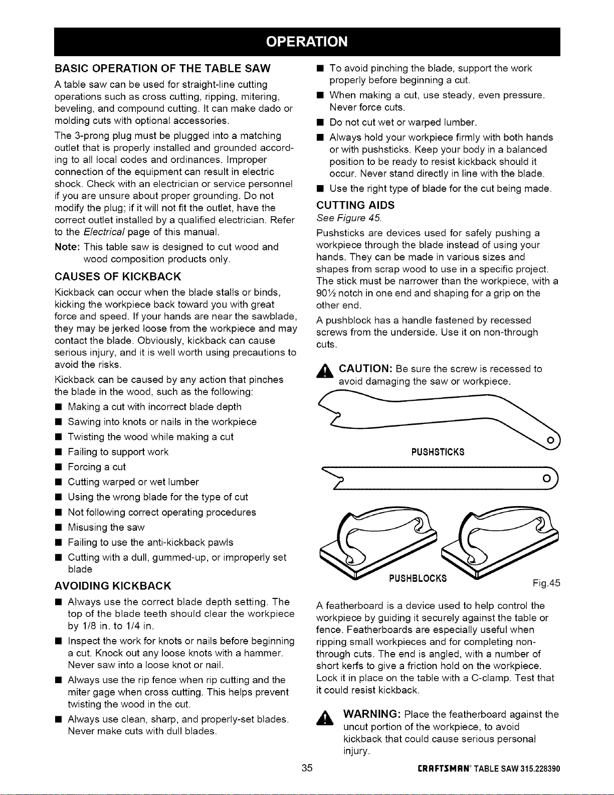
BASIC OPERATION OF THE TABLE SAW
A table saw can be used for straight-line cutting
operations such as cross cutting, ripping, mitering,
beveling, and compound cutting. It can make dado or
molding cuts with optional accessories.
The 3-prong plug must be plugged into a matching
outlet that is properly installed and grounded accord-
ing to all local codes and ordinances. Improper
connection of the equipment can result in electric
shock. Check with an electrician or service personnel
if you are unsure about proper grounding. Do not
modify the plug; if it will not fit the outlet, have the
correct outlet installed by a qualified electrician. Refer
to the Electrical page of this manual.
Note: This table saw is designed to cut wood and
wood composition products only.
CAUSES OF KICKBACK
Kickback can occur when the blade stalls or binds,
kicking the workpiece back toward you with great
force and speed, tf your hands are near the sawblade,
they may be jerked loose from the workpiece and may
contact the blade. Obviously, kickback can cause
serious injury, and it is well worth using precautions to
avoid the risks.
Kickback can be caused by any action that pinches
the blade in the wood, such as the following:
• Making a cut with incorrect blade depth
• Sawing into knots or nails in the workpiece
• Twisting the wood while making a cut
• Failing to support work
• Forcing a cut
• Cutting warped or wet lumber
• Using the wrong blade for the type of cut
• Not following correct operating procedures
• Misusing the saw
• Failing to use the anti-kickback pawls
• Cutting with a dull, gummed-up, or improperly set
blade
AVOIDING KICKBACK
• Always use the correct blade depth setting. The
top of the blade teeth should clear the workpiece
by 1/8 in. to 1/4 in.
• Inspect the work for knots or nails before beginning
a cut. Knock out any loose knots with a hammer.
Never saw into a loose knot or nail.
• Always use the rip fence when rip cutting and the
miter gage when cross cutting. This helps prevent
twisting the wood in the cut.
• Always use clean, sharp, and properly-set blades.
Never make cuts with dull blades.
• To avoid pinching the blade, support the work
properly before beginning a cut.
• When making a cut, use steady, even pressure.
Never force cuts.
• Do not cut wet or warped lumber.
• Always hold your workpiece firmly with both hands
or with pushsticks. Keep your body in a balanced
position to be ready to resist kickback should it
occur. Never stand directly in line with the blade.
• Use the right type of blade for the cut being made.
CUTTING AIDS
See Figure 45.
Pushsticks are devices used for safely pushing a
workpiece through the blade instead of using your
hands. They can be made in various sizes and
shapes from scrap wood to use in a specific project.
The stick must be narrower than the workpiece, with a
90½ notch in one end and shaping for a grip on the
other end.
A pushblock has a handle fastened by recessed
screws from the underside. Use it on non-through
cuts.
,_ CAUTION: Be sure the screw is recessed to
o
avoid damaging the saw or workpiece.
PUSHSTICK8
35
PUSHBLOCK8
Fig.45
A featherboard is a device used to help control the
workpiece by guiding it securely against the table or
fence. Featherboards are especially useful when
ripping small workpieces and for completing non-
through cuts. The end is angled, with a number of
short kerfs to give a friction hold on the workpiece.
Lock it in place on the table with a C-clamp. Test that
it could resist kickback.
A
WARNING: Place the featherboard against the
uncut portion of the workpiece, to avoid
kickback that could cause serious personal
injury.
rRRFI"$MRN°TABLESAW315.228390
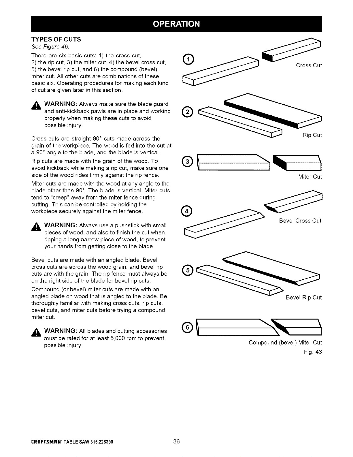
TYPES OF CUTS
See Figure 46.
There are six basic cuts: 1) the cross cut,
2) the rip cut, 3) the miter cut, 4) the bevel cross cut,
5) the bevel rip cut, and 6) the compound (bevel)
miter cut. All other cuts are combinations of these
basic six. Operating procedures for making each kind
of cut are given later in this section.
_lh WARNING: Always make sure the blade guard
and anti-kickback pawls are in place and working
properly when making these cuts to avoid
possible injury.
Cross cuts are straight 90° cuts made across the
grain of the workpiece. The wood is fed into the cut at
a 90° angle to the blade, and the blade is vertical.
Rip cuts are made with the grain of the wood. To
avoid kickback while making a rip cut, make sure one
side of the wood rides firmly against the rip fence.
Miter cuts are made with the wood at any angle to the
blade other than 90 °. The blade is vertical. Miter cuts
tend to "creep" away from the miter fence during
cutting. This can be controlled by holding the
workpiece securely against the miter fence.
,_ WARNING: Always use a pushstick with small
pieces of wood, and also to finish the cut when
ripping a long narrow piece of wood, to prevent
your hands from getting close to the blade.
Bevel cuts are made with an angled blade. Bevel
cross cuts are across the wood grain, and bevel rip
cuts are with the grain. The rip fence must always be
on the right side of the blade for bevel rip cuts.
Compound (or bevel) miter cuts are made with an
angled blade on wood that is angled to the blade. Be
thoroughly familiar with making cross cuts, rip cuts,
bevel cuts, and miter cuts before trying a compound
miter cut.
,_ WARNING: All blades and cutting accessories
must be rated for at least 5,000 rpm to prevent
possible injury.
Cross Cut
Rip Cut
Miter Cut
Bevel Rip Cut
Compound (bevel) Miter Cut
Fig. 46
rRRFTSMRN * TABLESAW315.228390 36
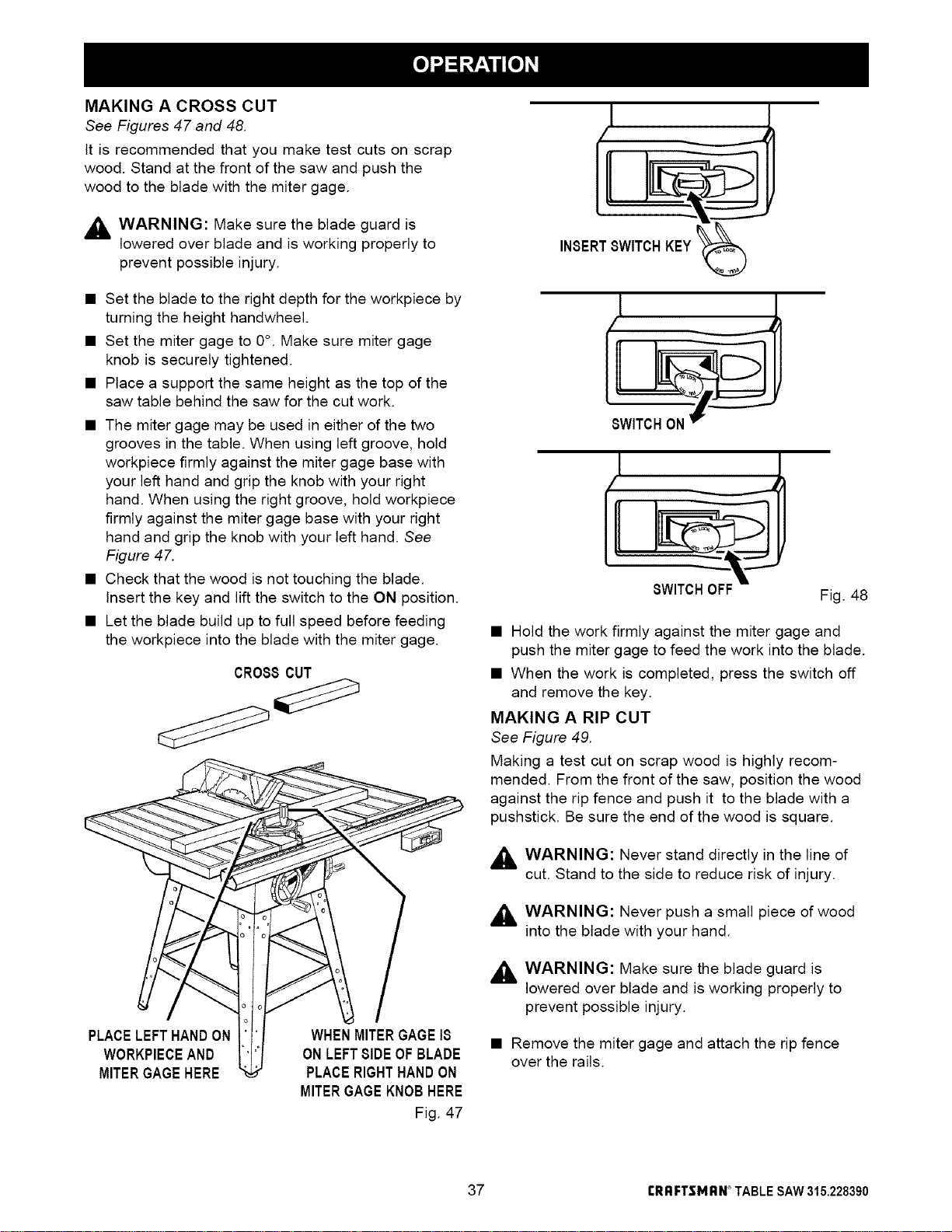
MAKING A CROSS CUT
See Figures 47 and 48.
It is recommended that you make test cuts on scrap
wood. Stand at the front of the saw and push the
wood to the blade with the miter gage.
,_ WARNING: Make sure the blade guard is
lowered over blade and is working properly to
prevent possible injury.
• Set the blade to the right depth for the workpiece by
turning the height handwheel.
• Set the miter gage to 0°. Make sure miter gage
knob is securely tightened.
• Place a support the same height as the top of the
saw table behind the saw for the cut work.
• The miter gage may be used in either of the two
grooves in the table. When using left groove, hold
workpiece firmly against the miter gage base with
your left hand and grip the knob with your right
hand. When using the right groove, hold workpiece
firmly against the miter gage base with your right
hand and grip the knob with your left hand. See
Figure 47.
• Check that the wood is not touching the blade.
Insert the key and lift the switch to the ON position.
• Let the blade build up to full speed before feeding
the workpiece into the blade with the miter gage.
0R088 CUT
PLACELEFTHANDON
WORKPIECEAND
MITERGAGEHERE
WHENMITERGAGE18
ONLEFT81DEOFBLADE
PLACERIGHTHANDON
MITERGAGEKNOBHERE
Fig. 47
INSERT8WITCHKEY
l
un
Fig. 48
• Hold the work firmly against the miter gage and
push the miter gage to feed the work into the blade.
• When the work is completed, press the switch off
and remove the key.
MAKING A RIP CUT
See Figure 49.
Making a test cut on scrap wood is highly recom-
mended. From the front of the saw, position the wood
against the rip fence and push it to the blade with a
pushstick. Be sure the end of the wood is square.
,_ WARNING: Never stand directly in the line of
cut. Stand to the side to reduce risk of injury.
,_ WARNING: Never push a small piece of wood
into the blade with your hand.
,_ WARNING: Make sure the blade guard is
lowered over blade and is working properly to
prevent possible injury.
• Remove the miter gage and attach the rip fence
over the rails.
37 rRRFTSMRN ° TABLESAW315.228390
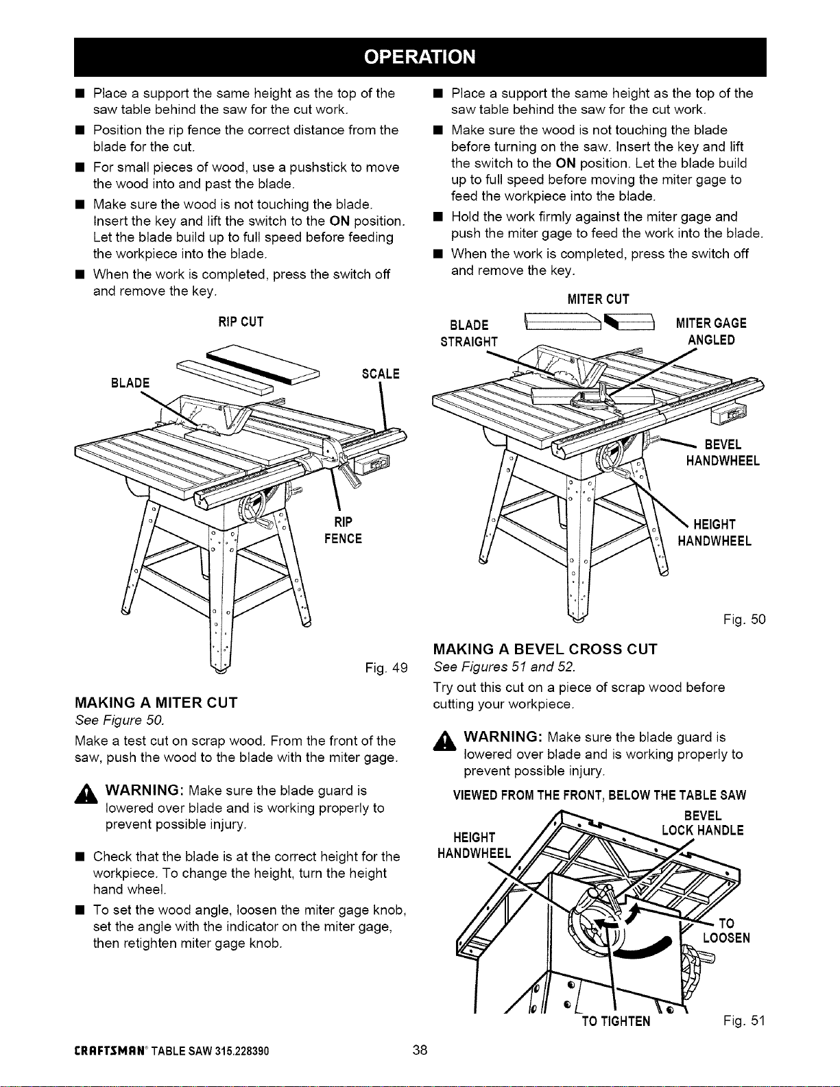
• Place a support the same height as the top of the
saw table behind the saw for the cut work.
• Position the rip fence the correct distance from the
blade for the cut.
• For small pieces of wood, use a pushstick to move
the wood into and past the blade.
• Make sure the wood is not touching the blade.
Insert the key and lift the switch to the ON position.
Let the blade build up to full speed before feeding
the workpiece into the blade.
• When the work is completed, press the switch off
and remove the key.
RIPCUT
BLADE __ SCALE
__ili_ FENCE,Fig. 49
MAKING A MITER CUT
See Figure 50.
Make a test cut on scrap wood. From the front of the
saw, push the wood to the blade with the miter gage.
_ WARNING: Make sure the blade guard is
lowered over blade and is working properly to
prevent possible injury.
• Check that the blade is at the correct height for the
workpiece. To change the height, turn the height
hand wheel.
• To set the wood angle, loosen the miter gage knob,
set the angle with the indicator on the miter gage,
then retighten miter gage knob.
• Place a support the same height as the top of the
saw table behind the saw for the cut work.
• Make sure the wood is not touching the blade
before turning on the saw. Insert the key and lift
the switch to the ON position. Let the blade build
up to full speed before moving the miter gage to
feed the workpiece into the blade.
• Hold the work firmly against the miter gage and
push the miter gage to feed the work into the blade.
• When the work is completed, press the switch off
and remove the key.
MITERCUT
BLADE _ MITERGAGE
STRAIGHT ANGLED
BEVEL
HANDWHEEL
HEIGHT
HANDWHEEL
Fig. 50
MAKING A BEVEL CROSS CUT
See Figures 51 and 52.
Try out this cut on a piece of scrap wood before
cutting your workpiece.
_ WARNING: Make sure the blade guard is
lowered over blade and is working properly to
prevent possible injury.
VIEWEDFROMTHEFRONT,BELOWTHETABLESAW
BEVEL
LOCKHANDLE
HEIGHT
HANDWHEEL
TO
LOOSEN
TO TIGHTEN Fig. 51
rRFIFI"$MFIN_TABLESAW315.228390 38
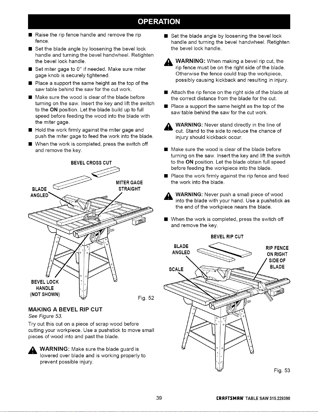
• Raise the rip fence handle and remove the rip
fence.
• Set the blade angle by loosening the bevel lock
handle and turning the bevel handwheel. Retighten
the bevel lock handle.
• Set miter gage to 0° if needed. Make sure miter
gage knob is securely tightened.
• Place a support the same height as the top of the
saw table behind the saw for the cut work.
• Make sure the wood is clear of the blade before
turning on the saw. Insert the key and lift the switch
to the ON position. Let the blade build up to full
speed before feeding the wood into the blade with
the miter gage.
• Hold the work firmly against the miter gage and
push the miter gage to feed the work into the blade.
• When the work is completed, press the switch off
and remove the key.
BLADE
ANGLED_
BEVELLOCK
HANDLE
(NOTSHOWN)
BEVELCROSSCUT
/
Fig. 52
MAKING A BEVEL RIP CUT
See Figure 53.
Try out this cut on a piece of scrap wood before
cutting your workpiece. Use a pushstick to move small
pieces of wood into and past the blade.
,_ WARNING: Make sure the blade guard is
lowered over blade and is working properly to
prevent possible injury.
• Set the blade angle by loosening the bevel lock
handle and turning the bevel handwheel. Retighten
the bevel lock handle.
,_ WARNING: When making a bevel rip cut, the
rip fence must be on the right side of the blade.
Otherwise the fence could trap the workpiece,
possibly causing kickback and resulting in injury.
• Attach the rip fence on the right side of the blade at
the correct distance from the blade for the cut.
• Place a support the same height as the top of the
saw table behind the saw for the cut work.
,_ WARNING: Never stand directly in the line of
cut. Stand to the side to reduce the chance of
injury should kickback occur.
• Make sure the wood is clear of the blade before
turning on the saw. Insert the key and lift the switch
to the ON position. Let the blade obtain full speed
before feeding the workpiece into the blade.
• Place the work firmly against the rip fence and feed
the work into the blade.
,_ WARNING: Never push a small piece of wood
into the blade with your hand. Use a pushstick as
the end of the workpiece nears the blade.
• When the work is completed, press the switch off
and remove the key.
BEVELRIPCUT
BLADE
ANGLED
RIPFENCE
ONRIGHT
SCALE
BLADE
Fig. 53
39 rRRFTSMRN ° TABLESAW315.228390
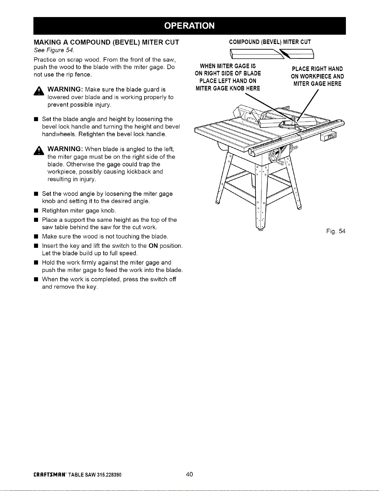
MAKING A COMPOUND (BEVEL) MITER CUT
See Figure 54.
Practice on scrap wood. From the front of the saw,
push the wood to the blade with the miter gage. Do
not use the rip fence.
,_ WARNING: Make sure the blade guard is
lowered over blade and is working properly to
prevent possible injury.
• Set the blade angle and height by loosening the
bevel lock handle and turning the height and bevel
handwheels. Retighten the bevel lock handle.
,_ WARNING: When blade is angled to the left,
the miter gage must be on the right side of the
blade. Otherwise the gage could trap the
workpiece, possibly causing kickback and
resulting in injury.
• Set the wood angle by loosening the miter gage
knob and setting it to the desired angle.
• Retighten miter gage knob.
• Place a support the same height as the top of the
saw table behind the saw for the cut work.
• Make sure the wood is not touching the blade.
• Insert the key and lift the switch to the ON position.
Let the blade build up to full speed.
• Hold the work firmly against the miter gage and
push the miter gage to feed the work into the blade.
• When the work is completed, press the switch off
and remove the key.
COMPOUND(BEVEL)MITERCUT
WHENMITERGAGE18
ONRIGHT81DEOFBLADE
PLACELEFTHANDON
MITERGAGEKNOBHERE
PLACERIGHTHAND
ONWORKPIECEAND
MITERGAGEHERE
Fig. 54
rRRFTSMRN * TABLESAW315.228390 40
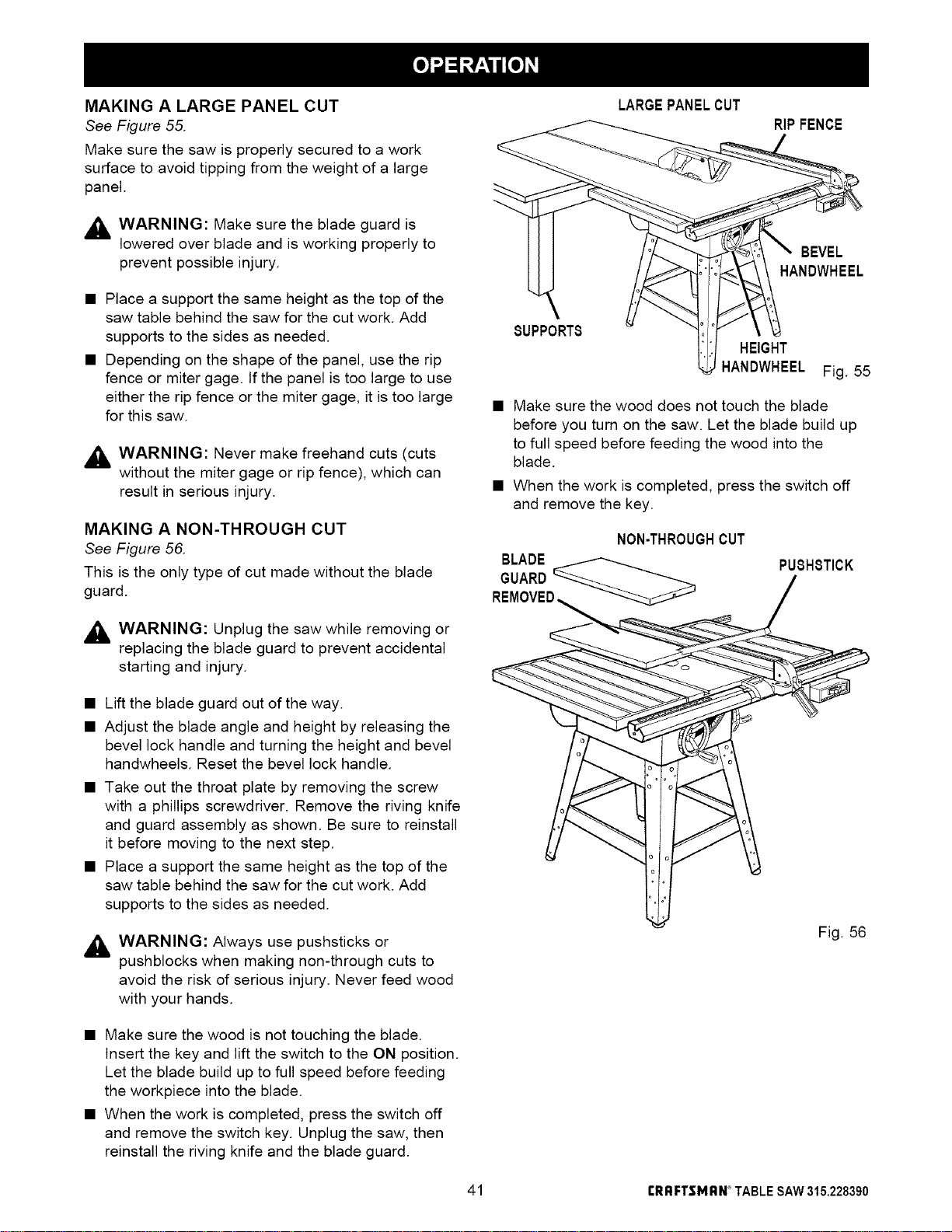
MAKING A LARGE PANEL CUT
See Figure 55.
Make sure the saw is properly secured to a work
surface to avoid tipping from the weight of a large
panel.
,_ WARNING: Make sure the blade guard is
lowered over blade and is working properly to
prevent possible injury.
• Place a support the same height as the top of the
saw table behind the saw for the cut work. Add
supports to the sides as needed.
• Depending on the shape of the panel, use the rip
fence or miter gage. tf the panel is too large to use
either the rip fence or the miter gage, it is too large
for this saw.
,_ WARNING: Never make freehand cuts (cuts
without the miter gage or rip fence), which can
result in serious injury.
MAKING A NON-THROUGH CUT
See Figure 56.
This is the only type of cut made without the blade
guard.
,_ WARNING: Unplug the saw while removing or
replacing the blade guard to prevent accidental
starting and injury.
LARGEPANELCUT
RIP FENCE
BEVEL
HANDWHEEL
SUPPORTS
HEIGHT
HANDWHEEL Fig. 55
• Make sure the wood does not touch the blade
before you turn on the saw. Let the blade build up
to full speed before feeding the wood into the
blade.
• When the work is completed, press the switch off
and remove the key.
NON-THROUGHCUT
BLADE _
GUARD
PUSHSTICK
• Lift the blade guard out of the way.
• Adjust the blade angle and height by releasing the
bevel lock handle and turning the height and bevel
handwheels. Reset the bevel lock handle.
• Take out the throat plate by removing the screw
with a phillips screwdriver. Remove the riving knife
and guard assembly as shown. Be sure to reinstall
it before moving to the next step.
• Place a support the same height as the top of the
saw table behind the saw for the cut work. Add
supports to the sides as needed.
,_ WARNING: Always use pushsticks or
pushblocks when making non-through cuts to
avoid the risk of serious injury. Never feed wood
with your hands.
Fig. 56
• Make sure the wood is not touching the blade.
Insert the key and lift the switch to the ON position.
Let the blade build up to full speed before feeding
the workpiece into the blade.
• When the work is completed, press the switch off
and remove the switch key. Unplug the saw, then
reinstall the riving knife and the blade guard.
41 rRRF'rSMRN ° TABLESAW315.228390
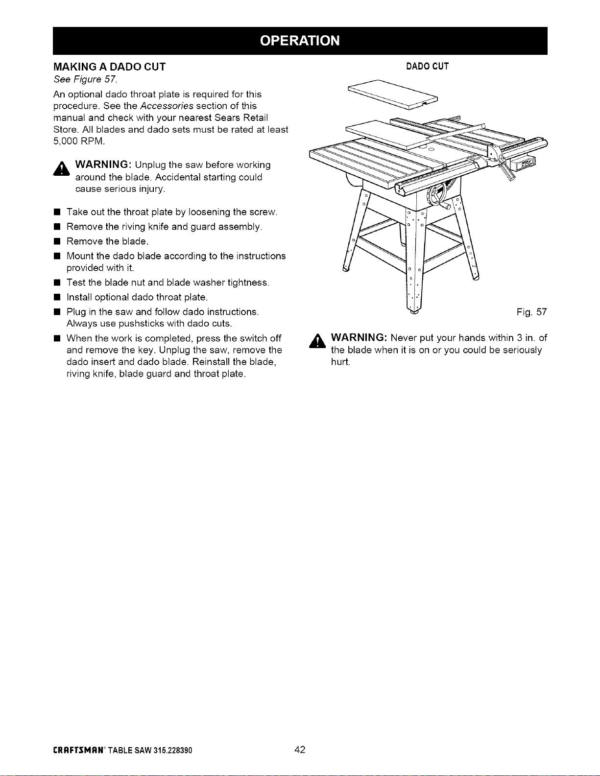
MAKING A DADO CUT
See Figure 57.
An optiona( dado throat plate is required for this
procedure. See the Accessories section of this
manua( and check with your nearest Sears Retail
Store. A(I b(ades and dado sets must be rated at least
5,000 RPM.
WARNING: Unplug the saw before working
around the blade. Accidental starting could
cause serious injury.
• Take out the throat plate by loosening the screw.
• Remove the riving knife and guard assembly.
• Remove the blade.
• Mount the dado blade according to the instructions
provided with it.
• Test the blade nut and blade washer tightness.
• Install optional dado throat plate.
• Plug in the saw and follow dado instructions.
Always use pushsticks with dado cuts.
• When the work is completed, press the switch off
and remove the key. Unplug the saw, remove the
dado insert and dado blade. Reinstall the blade,
riving knife, blade guard and throat plate.
DADOCUT
Fig. 57
,_k WARNING: Never put your hands within 3 in. of
the blade when it is on or you could be seriously
hurt.
I'RR FI"$MRN* TABLESAW315.228390 42
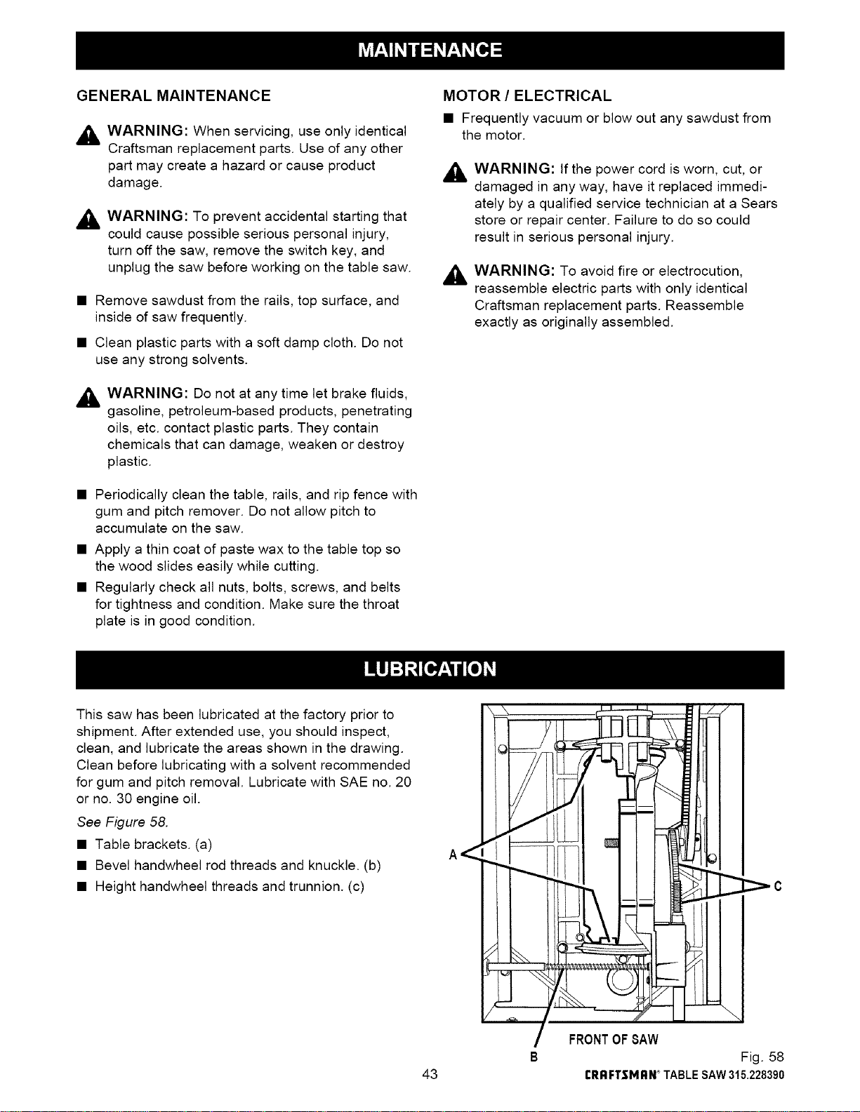
GENERAL MAINTENANCE
,_ WARNING: When servicing, use only identical
Craftsman replacement parts. Use of any other
part may create a hazard or cause product
damage.
,_ WARNING: To prevent accidental starting that
could cause possible serious personal injury,
turn off the saw, remove the switch key, and
unplug the saw before working on the table saw.
• Remove sawdust from the rails, top surface, and
inside of saw frequently.
• Clean plastic parts with a soft damp cloth. Do not
use any strong solvents.
,_ WARNING: Do not at any time let brake fluids,
gasoline, petroleum-based products, penetrating
oils, etc. contact plastic parts. They contain
chemicals that can damage, weaken or destroy
plastic.
• Periodically clean the table, rails, and rip fence with
gum and pitch remover. Do not allow pitch to
accumulate on the saw.
• Apply a thin coat of paste wax to the table top so
the wood slides easily while cutting.
• Regularly check all nuts, bolts, screws, and belts
for tightness and condition. Make sure the throat
plate is in good condition.
MOTOR / ELECTRICAL
• Frequently vacuum or blow out any sawdust from
the motor.
,_ WARNING: If the power cord is worn, cut, or
damaged in any way, have it replaced immedi-
ately by a qualified service technician at a Sears
store or repair center. Failure to do so could
result in serious personal injury.
,_ WARNING: To avoid fire or electrocution,
reassemble electric parts with only identical
Craftsman replacement parts. Reassemble
exactly as originally assembled.
This saw has been lubricated at the factory prior to
shipment. After extended use, you should inspect,
clean, and lubricate the areas shown in the drawing.
Clean before lubricating with a solvent recommended
for gum and pitch removal. Lubricate with SAE no. 20
or no. 30 engine oil.
See Figure 58.
• Table brackets. (a)
• Bevel handwheel rod threads and knuckle. (b)
• Height handwheel threads and trunnion. (c)
43
[:7-
FRONTOFSAW
B Fig. 58
rI_I_FTSMI:IN_TABLESAW315.228390
_'C
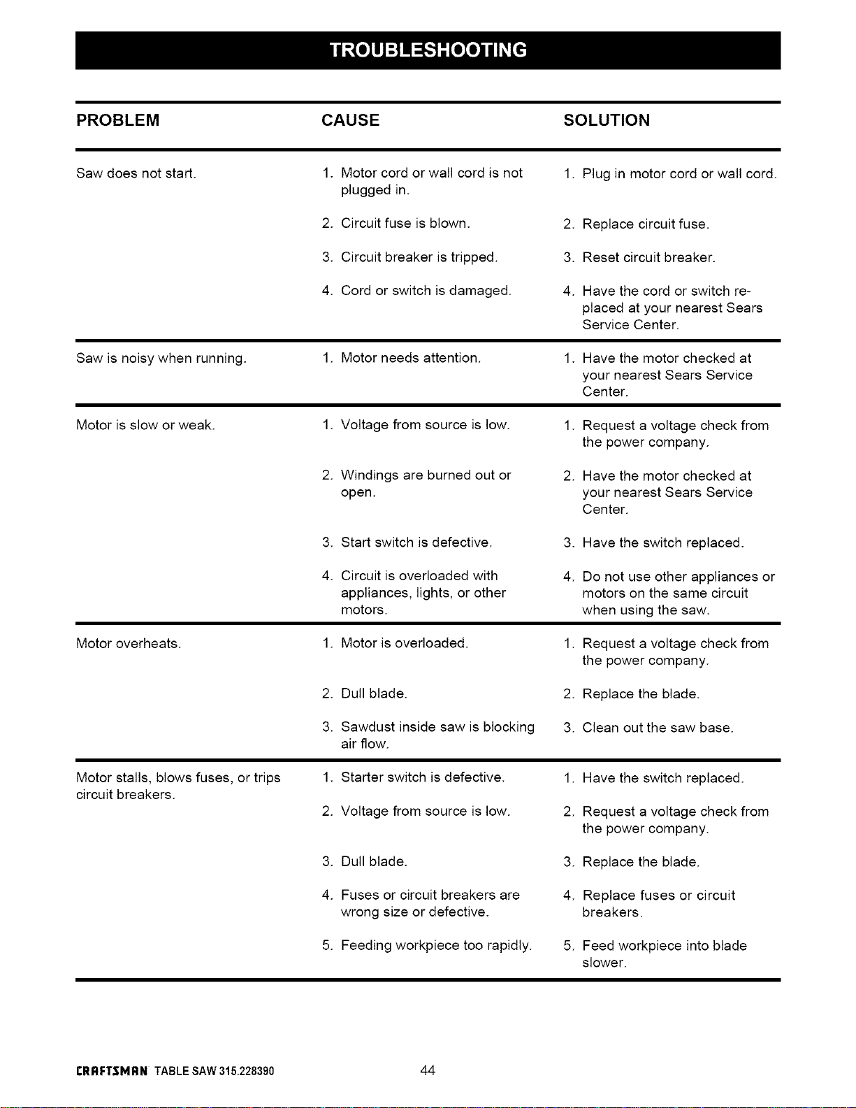
PROBLEM CAUSE SOLUTION
Saw does not start. 1. Motor cord or wall cord is not 1. Plug in motor cord or wall cord.
plugged in.
2. Circuit fuse is blown.
2. Replace circuit fuse.
3. Circuit breaker is tripped.
3. Reset circuit breaker.
4. Cord or switch is damaged.
4. Have the cord or switch re-
placed at your nearest Sears
Service Center.
Saw is noisy when running.
1. Motor needs attention. 1. Have the motor checked at
your nearest Sears Service
Center.
Motor is slow or weak.
1. Voltage from source is low.
1. Request a voltage check from
the power company.
2. Windings are burned out or
open.
2. Have the motor checked at
your nearest Sears Service
Center.
3. Start switch is defective.
3. Have the switch replaced.
4. Circuit is overloaded with
appliances, lights, or other
motors.
4. Do not use other appliances or
motors on the same circuit
when using the saw.
Motor overheats. 1. Motor is overloaded.
1. Request a voltage check from
the power company.
2. Dull blade. 2. Replace the blade.
3. Sawdust inside saw is blocking
air flow.
3. Clean out the saw base.
Motor stalls, blows fuses, or trips
circuit breakers.
1. Starter switch is defective.
2. Voltage from source is low.
1. Have the switch replaced.
2. Request a voltage check from
the power company.
3. Dull blade.
3. Replace the blade.
4. Fuses or circuit breakers are
wrong size or defective.
4. Replace fuses or circuit
breakers.
5. Feeding workpiece too rapidly. 5. Feed workpiece into blade
slower.
rRRFTIMRN TABLESAW315.228390 44
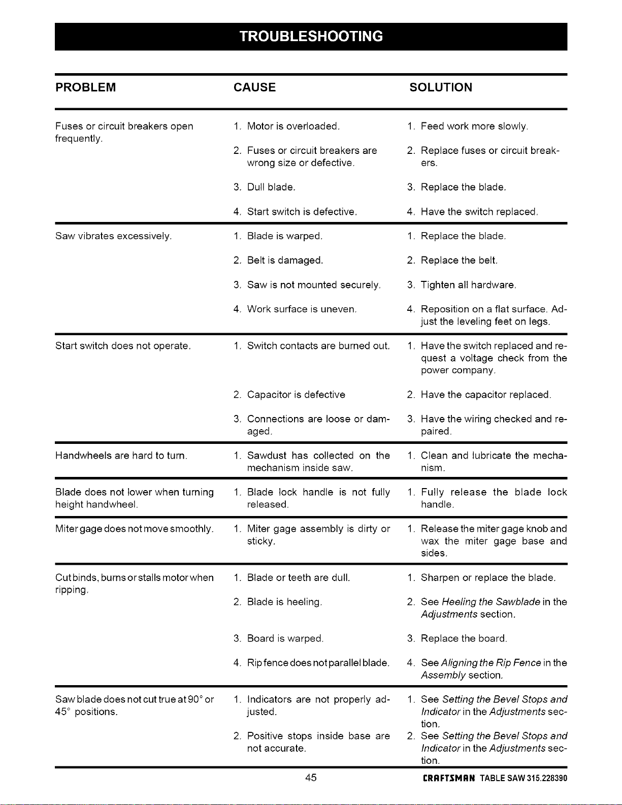
PROBLEM CAUSE SOLUTION
Fuses or circuit breakers open
frequently.
1. Motor is overloaded.
2. Fuses or circuit breakers are
wrong size or defective.
1. Feed work more slowly.
2. Replace fuses or circuit break-
ers.
3. Dull blade. 3. Replace the blade.
4. Start switch is defective.
4. Have the switch replaced.
Saw vibrates excessively. 1. Blade is warped. 1. Replace the blade.
2. Belt is damaged. 2. Replace the belt.
3. Saw is not mounted securely. 3. Tighten all hardware.
4. Work surface is uneven.
4. Reposition on a flat surface. Ad-
just the leveling feet on legs.
Start switch does not operate. 1. Switch contacts are burned out. 1. Have the switch replaced and re-
quest a voltage check from the
power company.
2. Capacitor is defective 2. Have the capacitor replaced.
3. Connections are loose or dam- 3. Have the wiring checked and re-
aged. paired.
Handwheels are hard to turn. 1. Sawdust has collected on the 1. Clean and lubricate the mecha-
mechanism inside saw. nism.
Blade does not lower when turning
height handwheel.
1. Blade lock handle is not fully 1. Fully release the blade lock
released, handle.
Miter gage does not move smoothly. 1. Miter gage assembly is dirty or 1. Release the miter gage knob and
sticky, wax the miter gage base and
sides.
Cut binds, burns or stalls motor when
ripping.
1. Blade or teeth are dull.
2. Blade is heeling.
1. Sharpen or replace the blade.
2. See Heeling the Sawblade in the
Adjustments section.
3. Board is warped. 3. Replace the board.
4. Ripfencedoesnotparallelblade. 4. See Aligning the Rip Fence in the
Assembly section.
Saw blade does not cut true at 90°or
45° positions.
1. Indicators are not properly ad-
justed.
2. Positive stops inside base are
not accurate.
1. See Setting the Bevel Stops and
Indicator in the Adjustments sec-
tion.
2. See Setting the Bevel Stops and
Indicator in the Adjustments sec-
tion.
45 rRRFTSMRN TABLE SAW 315.228390
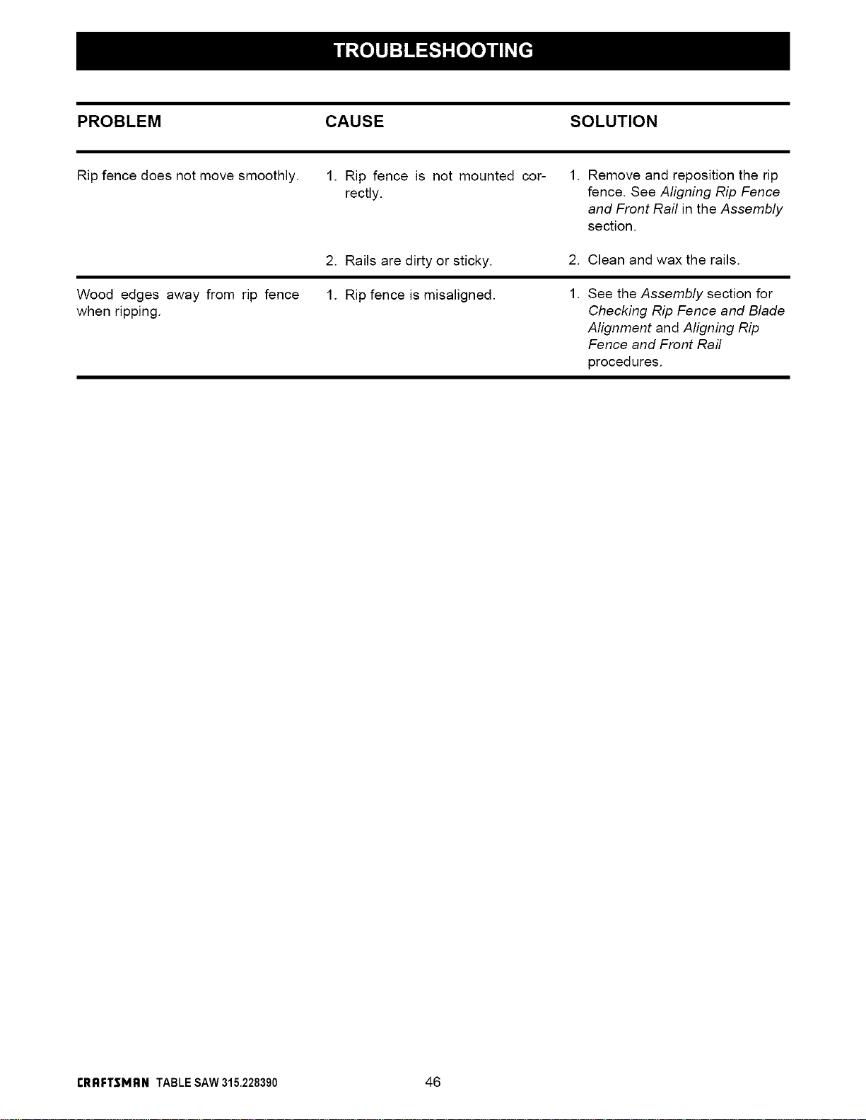
PROBLEM CAUSE SOLUTION
Rip fence does not move smoothly. 1. Rip fence is not mounted cor-
rectly.
1. Remove and reposition the rip
fence. See Aligning Rip Fence
and Front Rail in the Assembly
section.
2. Rails are dirty or sticky.
2. Clean and wax the rails.
Wood edges away from rip fence
when ripping.
1. Rip fence is misaligned.
1. See the Assembly section for
Checking Rip Fence and Blade
Alignment and Aligning Rip
Fence and Front Rail
procedures.
rRRFTIMRN TABLESAW315.228390 46

47 £RRFTSMRN TABLE SAW 315.228390
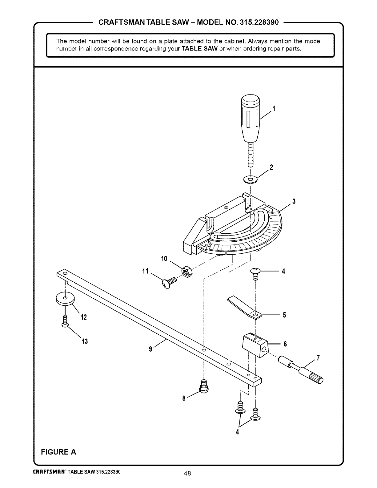
CRAFTSMAN TABLE SAW - MODEL NO. 315.228390 •
I The model number will be found on a plate attached to the cabinet. Always mention the model
number in all correspondence regarding your TABLE SAW or when ordering repair parts.
I
] /1
11
10 J
r
I
4
FIGURE A
rRRFTSMRN°TABLESAW315.228390
48
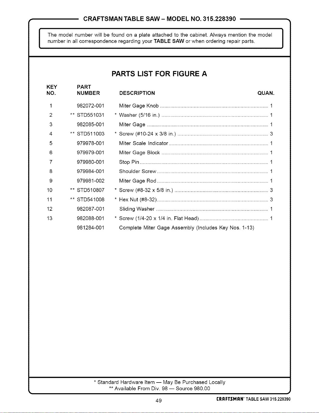
CRAFTSMAN TABLE SAW - MODEL NO. 315.228390 •
I The model number will be found on a plate attached to the cabinet. Always mention the model
number in all correspondence regarding your TABLE SAW or when ordering repair parts.
I
PARTS LIST FOR FIGURE A
KEY PART
NO. NUMBER DESCRIPTION QUAN.
1 982072-001
2 ** STD551031
3 982085-001
4 ** STD511003
5 979978-001
6 979979-001
7 979980-001
8 979984-001
9 979981-002
10 ** STD510807
11 ** STD541008
12 982087-001
13 982088-001
981284-001
Miter Gage Knob .......................................................................... 1
* Washer (5/16 in.) ......................................................................... 1
Miter Gage ................................................................................... 1
* Screw (#10-24 x 3/8 in.) .............................................................. 3
Miter Scale Indicator .................................................................... 1
Miter Gage Block ......................................................................... 1
Stop Pin ........................................................................................ 1
Shoulder Screw ............................................................................ 1
Miter Gage Rod ............................................................................ 1
* Screw (#8-32 x 5/8 in.) ................................................................ 3
* Hex Nut (#8-32) ............................................................................ 3
Sliding Washer ............................................................................. 1
* Screw (1/4-20 x 1/4 in. Flat Head) ............................................... 1
Complete Miter Gage Assembly (Includes Key Nos. 1-13)
* Standard Hardware Item -- May Be Purchased Locally
** Available From Div. 98 -- Source 980.00
#
49 rRRFTSMRN_TABLESAW315.228390
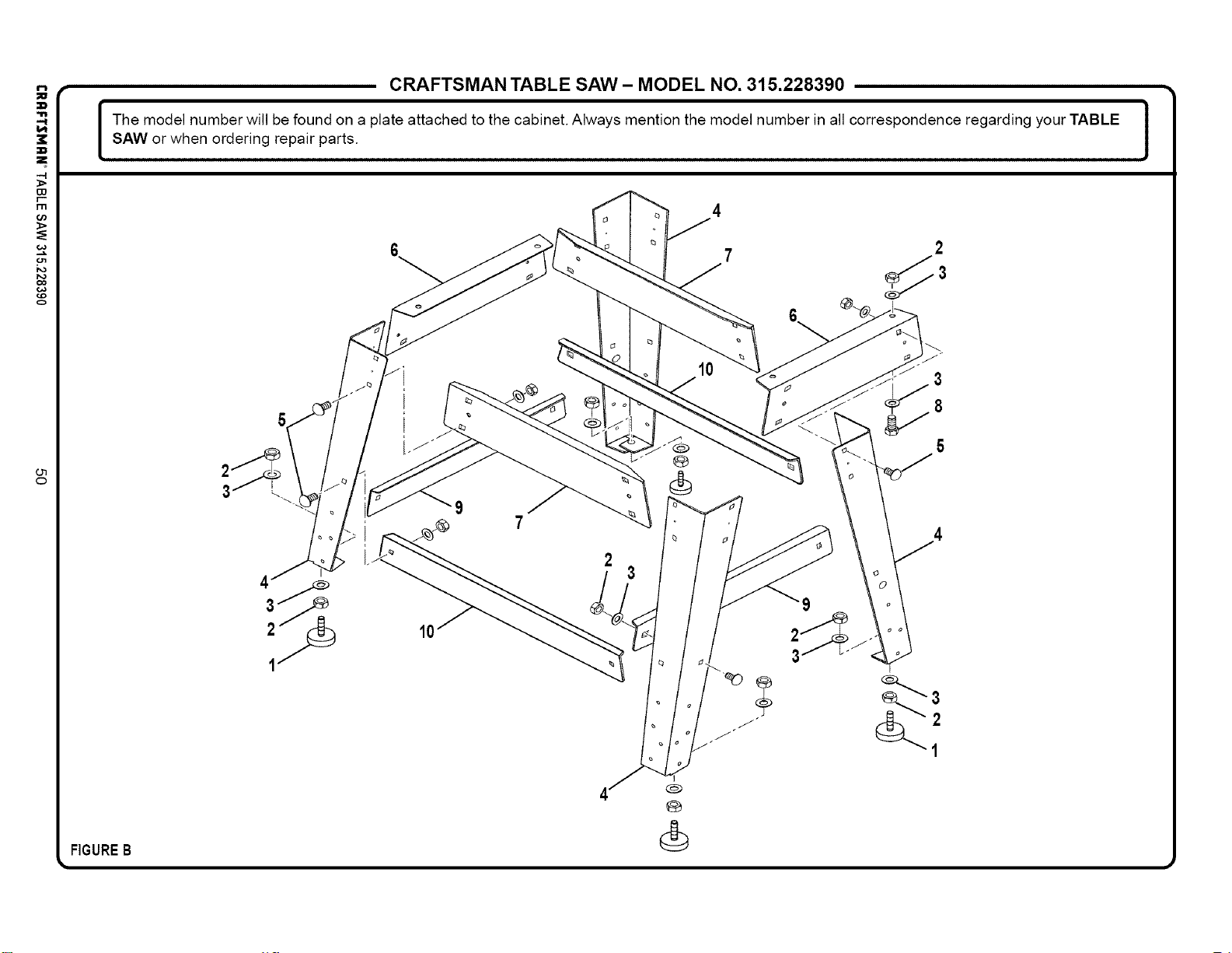
--I
r--
m
_>
co
€,o
o
FIGUREB
CRAFTSMAN TABLE SAW- MODEL NO. 315.228390 •
I he model number will be found on a plate attached to the cabinet. Always mention the model number in all correspondence regarding your TABLE I
SAW or when ordering repair parts.
J
2
®
10
1
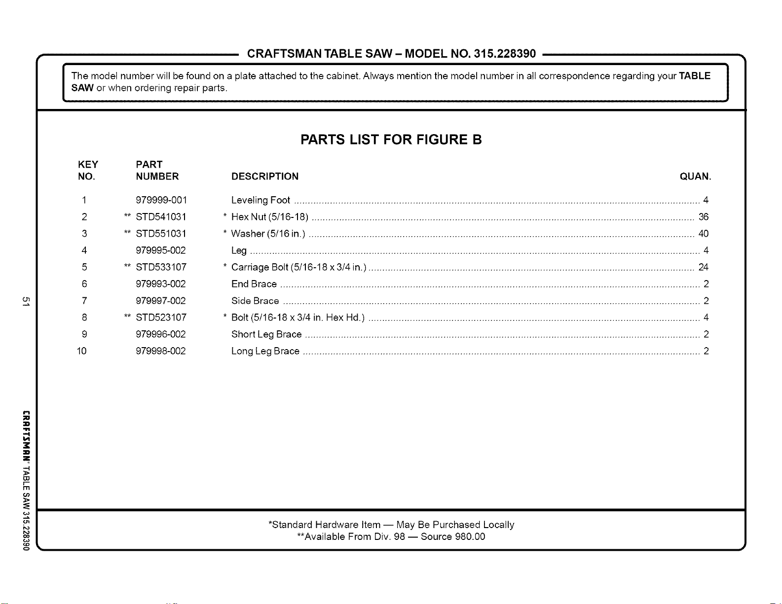
om
P.,
i
-4
W
I--
ill
0
CRAFTSMAN TABLE SAW- MODEL NO. 315.228390 •
I he model number will be found on a plate attached to the cabinet. Always mention the model number in all correspondence regarding your TABLE
SAW or when ordering repair parts.
J
PARTS LIST FOR FIGURE B
KEY PART
NO. NUMBER DESCRIPTION QUAN.
1 979999-001
2 ** STD541031
3 ** STD551031
4 979995-002
5 ** STD533107
6 979993-002
7 979997-002
8 ** STD523107
9 979996-002
10 979998-002
Leveling Foot ................................................................................................................................................... 4
* Hex Nut (5/16-18) ........................................................................................................................................... 36
* Washer (5/16 in.) ............................................................................................................................................ 40
Leg ................................................................................................................................................................... 4
* Carriage Bolt (5/16-18 x 3/4 in.) ...................................................................................................................... 24
End Brace ........................................................................................................................................................ 2
Side Brace ....................................................................................................................................................... 2
* Bolt (5/16-18 x 3/4 in. Hex Hd.) ........................................................................................................................ 4
Short Leg Brace ............................................................................................................................................... 2
Long Leg Brace ................................................................................................................................................ 2
*Standard Hardware Item -- May Be Purchased Locally
**Available From Div. 98 -- Source 980.00
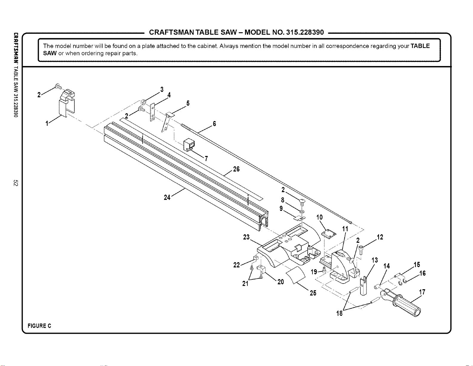
-4
I:O
13"1
Or)
_>
co
o
CRAFTSMAN TABLE SAW - MODEL NO. 315.228390 •
I he model number will be found on a plate attached to the cabinet. Always mention the model number in all correspondence regarding your TABLE
SAW or when ordering repair parts.
J
10
13
14
21
25
17
FIGUREC
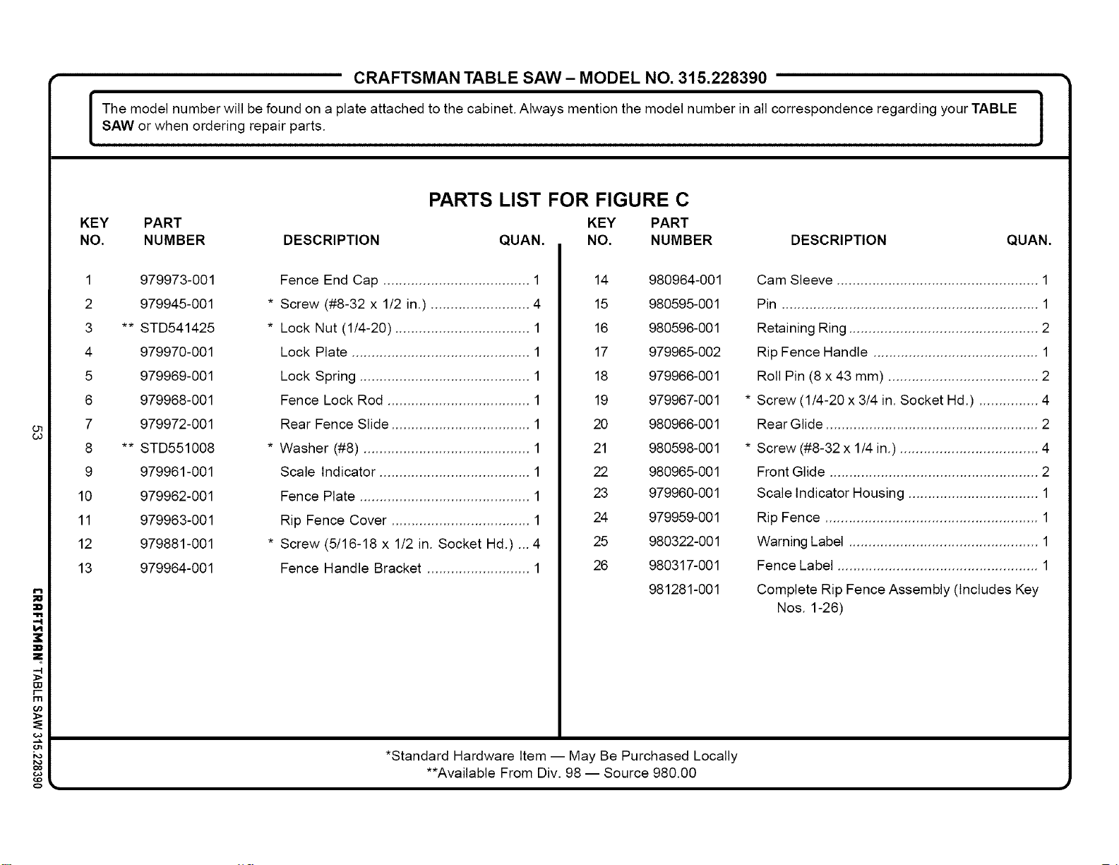
CRAFTSMAN TABLE SAW- MODEL NO. 315.228390 •
I he model number will be found on a plate attached to the cabinet. Always mention the model number in all correspondence regarding your TABLE J
SAW or when ordering repair parts.
J
PARTS LIST FOR FIGURE C
KEY PART KEY PART
NO. NUMBER DESCRIPTION QLJAN. NO. NUMBER DESCRIPTION QLJAN.
n
"4
x
313
r--
m
0o
co
o
1 979973-001
2 979945-001
3 ** STD541425
4 979970-001
5 979969-001
6 979968-001
7 979972-001
8 ** STD551008
9 979961-001
10 979962-001
11 979963-001
12 979881-001
13 979964-001
Fence End Cap ..................................... 1
* Screw (#8-32 x 1/2 in.) ......................... 4
* Lock Nut (1/4-20) .................................. 1
Lock Plate ............................................. 1
Lock Spring ........................................... 1
Fence Lock Rod .................................... 1
Rear Fence Slide ................................... 1
* Washer (#8) .......................................... 1
Scale Indicator ...................................... 1
Fence Plate ........................................... 1
Rip Fence Cover ................................... 1
* Screw (5/16-18 x 1/2 in. Socket Hd.) ...4
Fence Handle Bracket .......................... 1
14 980964-001
15 980595-001
16 980596-001
17 979965-002
18 979966-001
19 979967-001
20 980966-001
21 980598-001
22 980965-001
23 979960-001
24 979959-001
25 980322-001
26 980317-001
981281-001
*Standard Hardware Item -- May Be Purchased Locally
**Available From Div. 98 -- Source 980.00
Cam Sleeve ................................................... 1
Pin ................................................................. 1
Retaining Ring ................................................ 2
Rip Fence Handle .......................................... 1
Roll Pin (8 x 43 mm) ...................................... 2
* Screw (1/4-20 x 3/4 in. Socket Hd.) ............... 4
Rear Glide ...................................................... 2
* Screw (#8-32 x 1/4 in.) ................................... 4
Front Glide ..................................................... 2
Scale Indicator Housing ................................. 1
Rip Fence ...................................................... 1
Warning Label ................................................ 1
Fence Label ................................................... 1
Complete Rip Fence Assembly (Includes Key
Nos. 1-26)
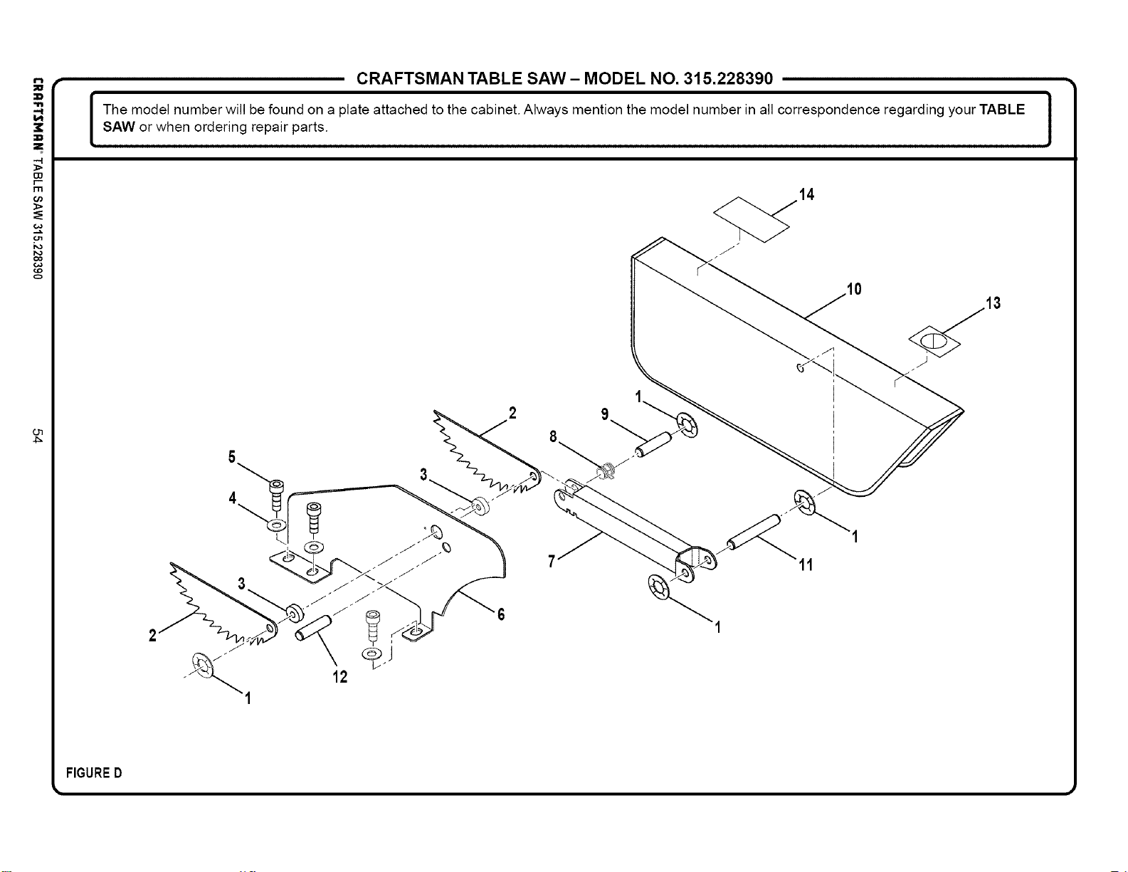
-4
r--
rn
0o
co
o
o'1
4_
CRAFTSMAN TABLE SAW- MODEL NO. 315.228390 •
I he model number will be found on a plate attached to the cabinet. Always mention the model number in all correspondence regarding your TABLE I
SAW or when ordering repair parts.
J
14
11
FIGURED
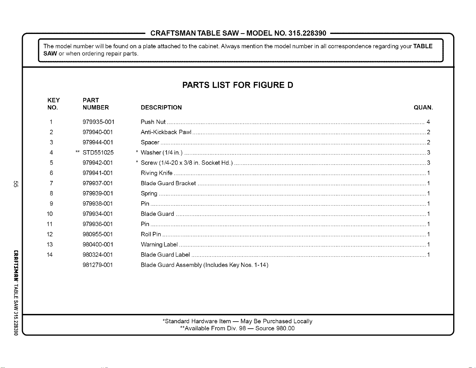
-4
138
r-
m
co
o
CRAFTSMAN TABLE SAW- MODEL NO. 315.228390 •
I he model number will be found on a plate attached to the cabinet. Always mention the model number in all correspondence regarding your TABLE
SAW or when ordering repair parts.
J
PARTS LIST FOR FIGURE D
KEY PART
NO. NUMBER DESCRIPTION QUAN.
1 979935-001
2 979940-001
3 979944-001
4 ** STD551025
5 979942-001
6 979941-001
7 979937-001
8 979939-001
9 979938-001
10 979934-001
11 979936-001
12 980955-001
13 980400-001
14 980324-001
981279-001
Push Nut ......................................................................................................................................................... 4
Anti-Kickback Pawl ........................................................................................................................................... 2
Spacer .............................................................................................................................................................. 2
Washer (1/4 in.) ................................................................................................................................................ 3
Screw (1/4-20 x 3/8 in. Socket Hd.) .................................................................................................................. 3
Riving Knife ...................................................................................................................................................... 1
Blade Guard Bracket ........................................................................................................................................ 1
Spring ............................................................................................................................................................... 1
Pin .................................................................................................................................................................... 1
Blade Guard ..................................................................................................................................................... 1
Pin .................................................................................................................................................................... 1
Roll Pin ............................................................................................................................................................. 1
Warning Label ................................................................................................................................................... 1
Blade Guard Label ............................................................................................................................................ 1
Blade Guard Assembly (Includes Key Nos. 1-14)
*Standard Hardware Item -- May Be Purchased Locally
**Available From Div. 98 -- Source 980.00
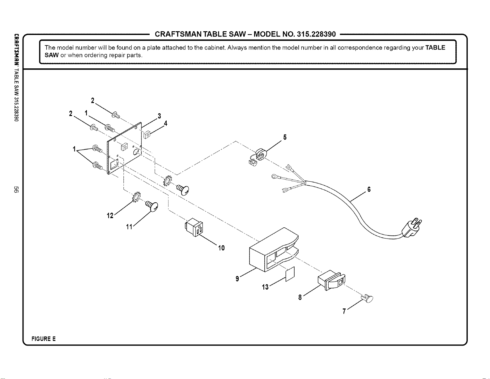
-4
r--
I"I"1
co
o
CRAFTSMAN TABLE SAW- MODEL NO. 315.228390 •
I he model number will be found on a plate attached to the cabinet. Always mention the model number in all correspondence regarding your TABLE
SAW or when ordering repair parts.
J
2
10
13
FIGUREE
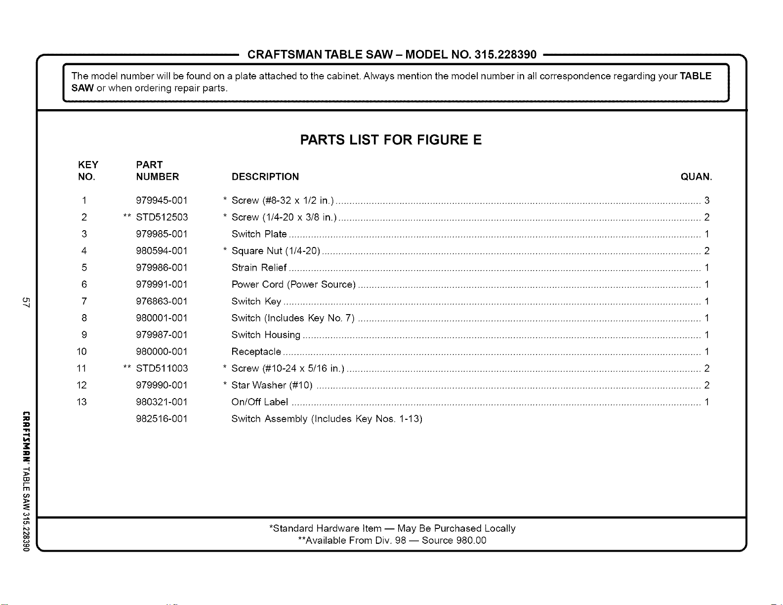
O7
"4
P.,
-4
W
r-
rlrl
o
CRAFTSMAN TABLE SAW- MODEL NO. 315.228390 •
I he model number will be found on a plate attached to the cabinet. Always mention the model number in all correspondence regarding your TABLE
SAW or when ordering repair parts.
J
PARTS LIST FOR FIGURE E
KEY PART
NO. NUMBER DESCRIPTION QUAN.
1 979945-001
2 ** STD512503
3 979985-001
4 980594-001
5 979986-001
6 979991-001
7 976863-001
8 980001-001
9 979987-001
10 980000-001
11 ** STD511003
12 979990-001
13 980321-001
982516-001
* Screw (#8-32 x 1/2 in.) .................................................................................................................................... 3
* Screw (1/4-20 x 3/8 in.) ................................................................................................................................... 2
Switch Plate ..................................................................................................................................................... 1
* Square Nut (1/4-20) ......................................................................................................................................... 2
Strain Relief ..................................................................................................................................................... 1
Power Cord (Power Source) ............................................................................................................................ 1
Switch Key ....................................................................................................................................................... 1
Switch (Includes Key No. 7) ............................................................................................................................ 1
Switch Housing ................................................................................................................................................ 1
Receptacle ....................................................................................................................................................... 1
* Screw (#10-24 x 5/16 in.) ................................................................................................................................ 2
* Star Washer (#10) ........................................................................................................................................... 2
On/Off Label .................................................................................................................................................... 1
Switch Assembly (Includes Key Nos. 1-13)
*Standard Hardware Item -- May Be Purchased Locally
**Available From Div. 98 -- Source 980.00
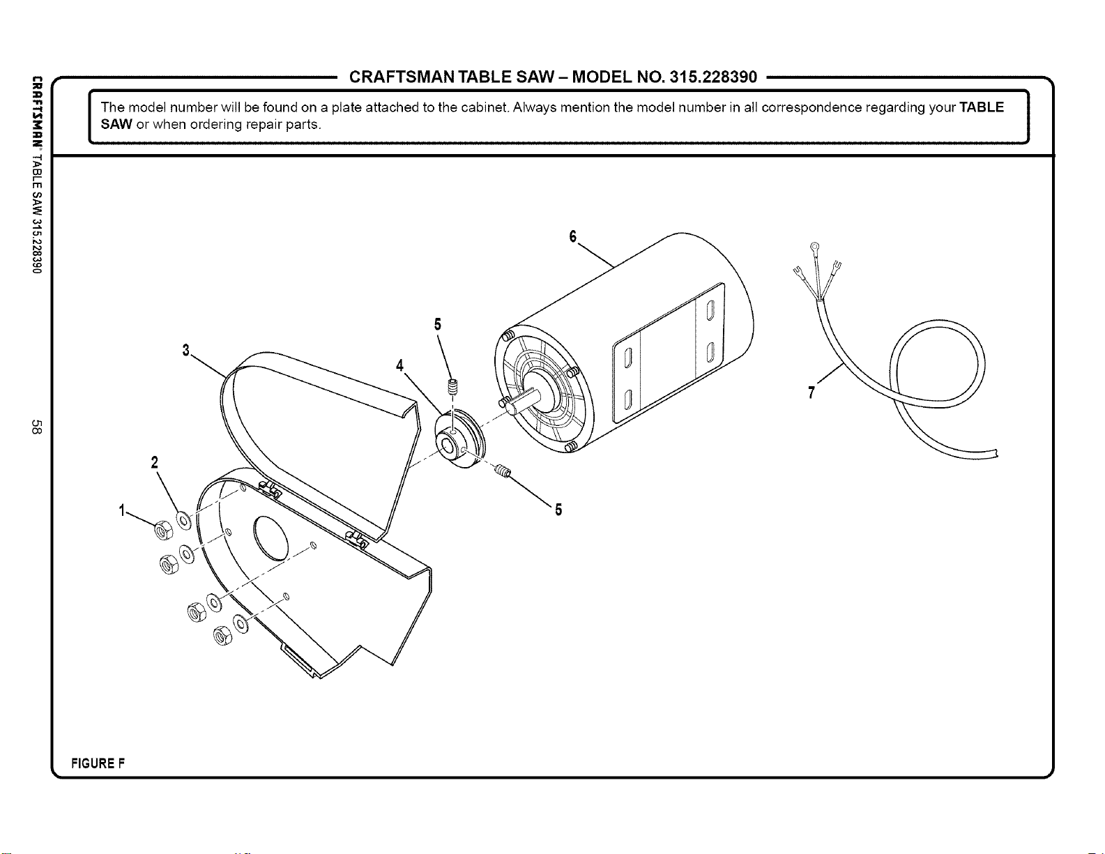
-4
r--
I"I"1
0o
co
o
CRAFTSMAN TABLE SAW- MODEL NO. 315.228390 •
I he model number will be found on a plate attached to the cabinet. Always mention the model number in all correspondence regarding your TABLE
SAW or when ordering repair parts.
J
6
\
FIGUREF
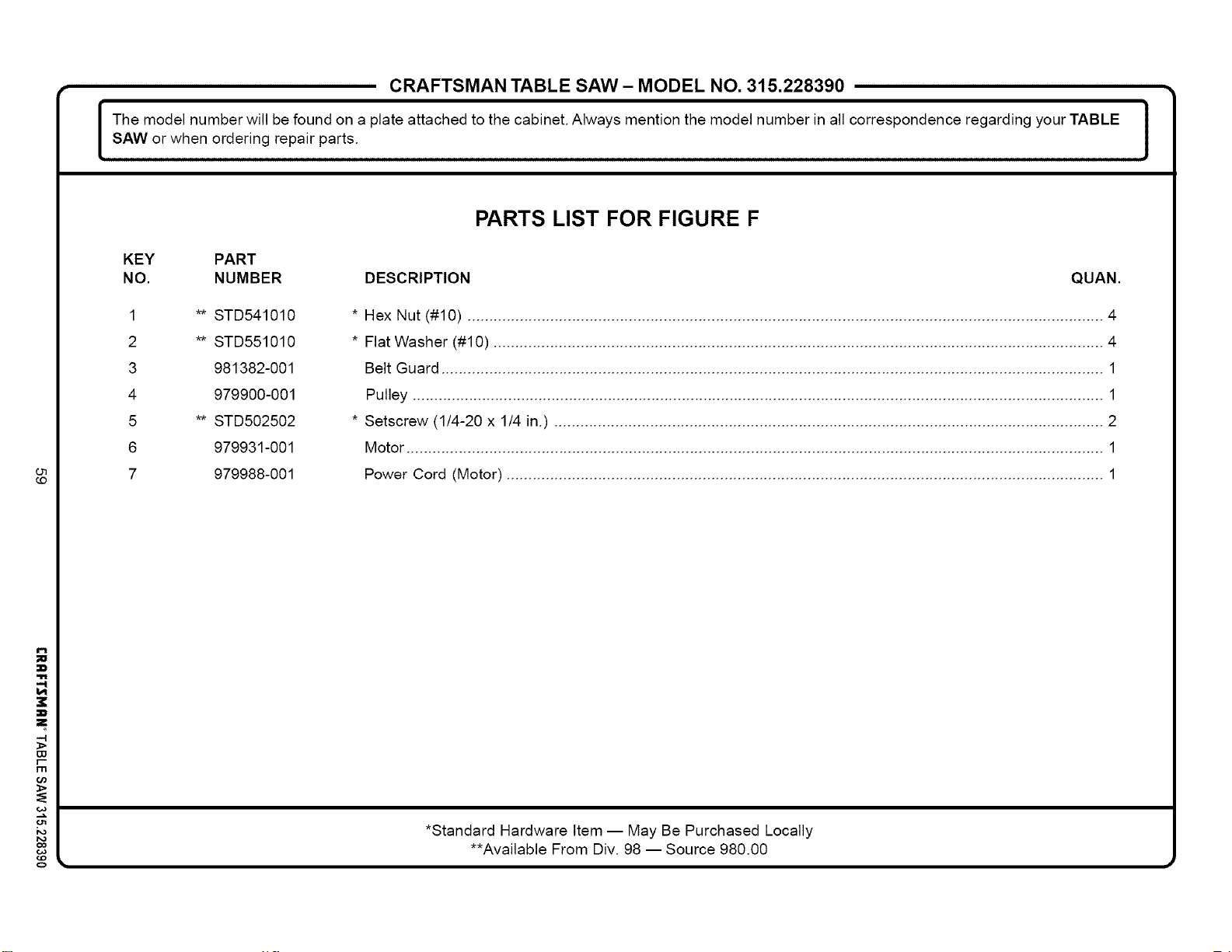
i
W
rrl
ka
co
o
CRAFTSMAN TABLE SAW- MODEL NO. 315.228390 •
I he model number will be found on a plate attached to the cabinet. Always mention the model number in all correspondence regarding your TABLE
SAW or when ordering repair parts.
J
PARTS LIST FOR FIGURE F
KEY PART
NO. NUMBER DESCRIPTION QUAN.
STD541010
STD551010
981382-001
979900-001
STD502502
979931-001
979988-001
1
2
3
4
5
6
7
* Hex Nut (#10) .................................................................................................................................................. 4
* Flat Washer (#10) ............................................................................................................................................ 4
Belt Guard ........................................................................................................................................................ 1
Pulley ............................................................................................................................................................... 1
* Setscrew (1/4-20 x 1/4 in.) .............................................................................................................................. 2
Motor ................................................................................................................................................................ 1
Power Cord (Motor) ......................................................................................................................................... 1
*Standard Hardware Item -- May Be Purchased Locally
**Available From Div. 98 -- Source 980.00
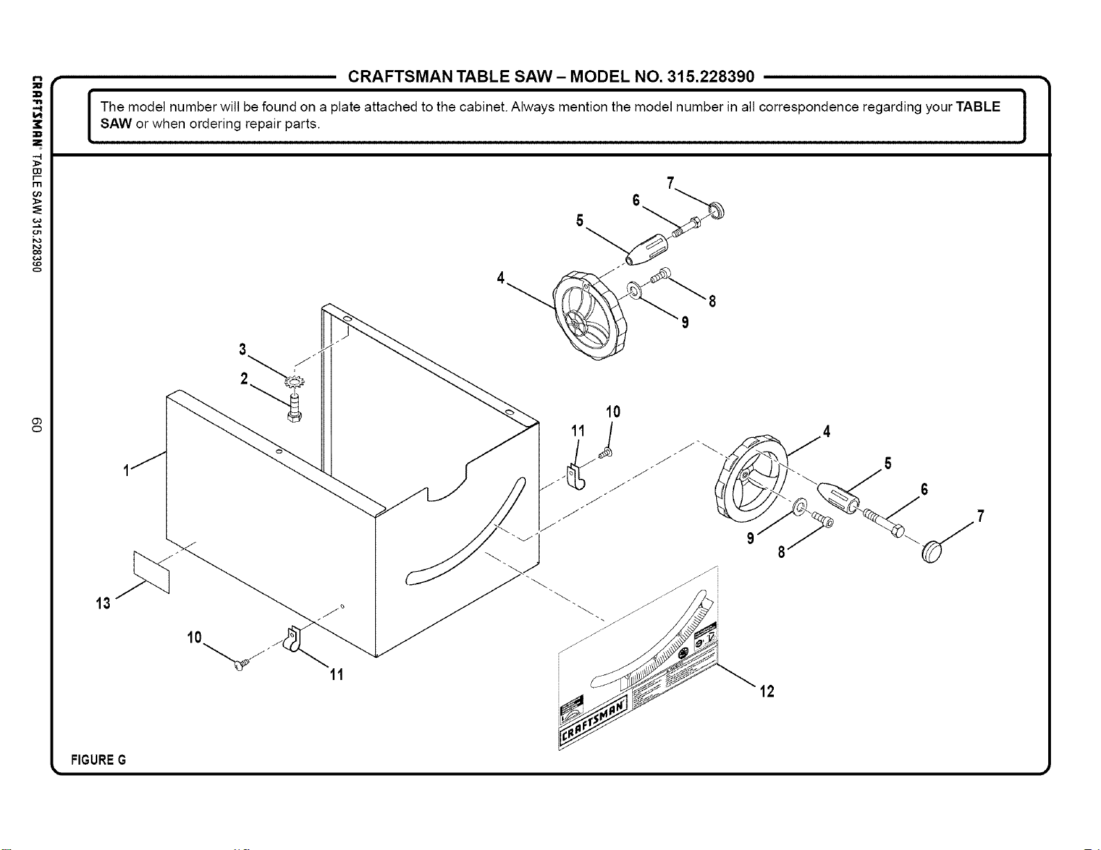
!
-4
r--
I"I"1
0o
=£
co
o
CRAFTSMAN TABLE SAW- MODEL NO. 315.228390 •
I he model number will be found on a plate attached to the cabinet. Always mention the model number in all correspondence regarding your TABLE
SAW or when ordering repair parts.
J
13
3
10
11
11
10
12
FIGUREG
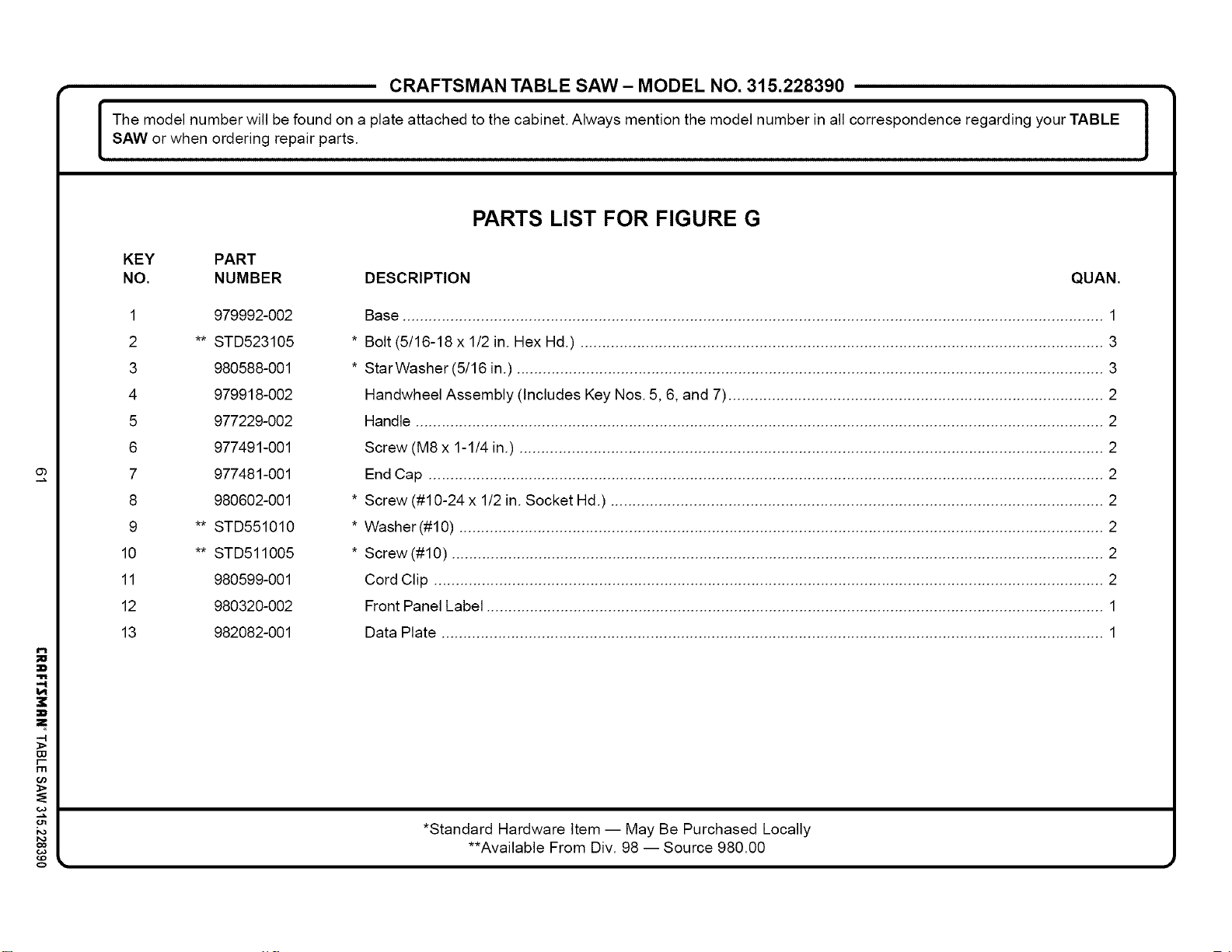
Ob
i
-4
W
r-
m
o
CRAFTSMAN TABLE SAW- MODEL NO. 315.228390 •
I he model number will be found on a plate attached to the cabinet. Always mention the model number in all correspondence regarding your TABLE
SAW or when ordering repair parts.
J
PARTS LIST FOR FIGURE G
KEY PART
NO. NUMBER DESCRIPTION QUAN.
1 979992-002
2 ** STD523105
3 980588-001
4 979918-002
5 977229-002
6 977491-001
7 977481-001
8 980602-001
9 ** STD551010
10 ** STD511005
11 980599-001
12 980320-002
13 982082-001
Base ................................................................................................................................................................. 1
* Bolt (5/16-18 x 1/2 in. Hex Hd.) ........................................................................................................................ 3
* StarWasher(5/16 in.) ....................................................................................................................................... 3
Handwheel Assembly (Includes Key Nos. 5, 6, and 7) ...................................................................................... 2
Handle .............................................................................................................................................................. 2
Screw (M8 x 1-1/4 in.) ...................................................................................................................................... 2
End Cap ........................................................................................................................................................... 2
* Screw (#10-24 x 1/2 in. Socket Hd.) ................................................................................................................. 2
* Washer (#10) .................................................................................................................................................... 2
* Screw (#10) ...................................................................................................................................................... 2
Cord Clip .......................................................................................................................................................... 2
Front Panel Label .............................................................................................................................................. 1
Data Plate ........................................................................................................................................................ 1
*Standard Hardware Item -- May Be Purchased Locally
**Available From Div. 98 -- Source 980.00
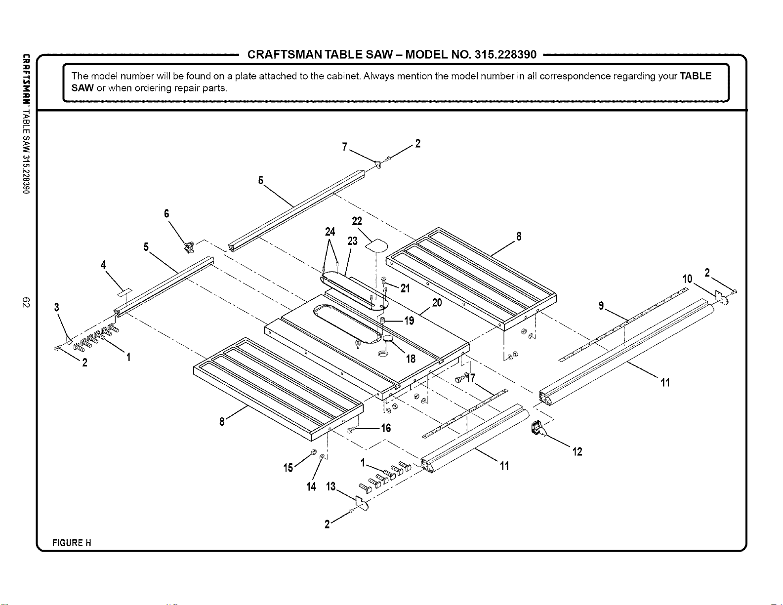
-4
r--
I"I"1
0o
co
o
CRAFTSMAN TABLE SAW- MODEL NO. 315.228390 •
I he model number will be found on a plate attached to the cabinet. Always mention the model number in all correspondence regarding your TABLE
SAW or when ordering repair parts.
J
2 1
11
12
11
FIGUREH
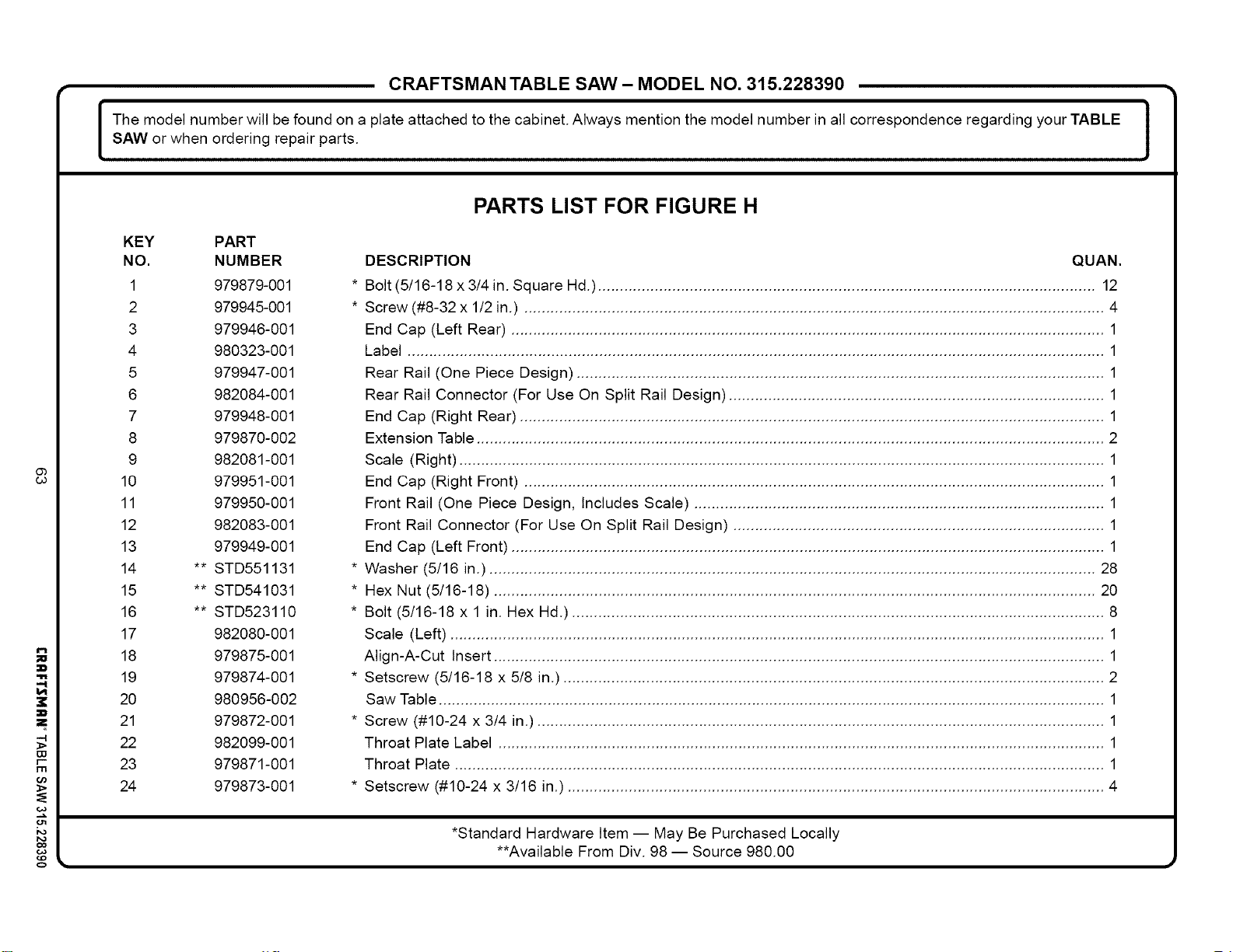
i
-4
W
r-
rlrl
o
CRAFTSMAN TABLE SAW - MODEL NO. 315.228390
I he model number will be found on a plate attached to the cabinet. Always mention the model number in all correspondence regarding your TABLE
SAW or when ordering repair parts.
J
KEY PART
NO. NUMBER
1 979879-001
2 979945-001
3 979946-001
4 980323-001
5 979947-001
6 982084-001
7 979948-001
8 979870-002
9 982081-001
10 979951-001
11 979950-001
12 982083-001
13 979949-001
14 ** STD551131
15 ** STD541031
16 ** STD523110
17 982080-001
18 979875-001
19 979874-001
20 980956-002
21 979672-001
22 982099-001
23 979871-001
24 979873-001
PARTS LIST FOR FIGURE H
DESCRIPTION QUAN.
* Bolt (5/16-18x3/4in. Square Hd.) .................................................................................................................. 12
* Screw (#8-32 x 1/2 in.) ..................................................................................................................................... 4
End Cap (Left Rear) ........................................................................................................................................ 1
Label ................................................................................................................................................................ 1
Rear Rail (One Piece Design) ......................................................................................................................... 1
Rear Rail Connector (For Use On Split Rail Design) ...................................................................................... 1
End Cap (Right Rear) ...................................................................................................................................... 1
Extension Table ................................................................................................................................................ 2
Scale (Right) .................................................................................................................................................... 1
End Cap (Right Front) ..................................................................................................................................... 1
Front Rail (One Piece Design, Includes Scale) .............................................................................................. 1
Front Rail Connector (For Use On Split Rail Design) ..................................................................................... 1
End Cap (Left Front) ........................................................................................................................................ 1
* Washer (5/16 in.) ........................................................................................................................................... 28
* Hex Nut (5/16-18) .......................................................................................................................................... 20
* Bolt (5/16-18 x 1 in. Hex Hd.) .......................................................................................................................... 8
Scale (Left) ...................................................................................................................................................... 1
Align-A-Cut Insert ............................................................................................................................................ 1
* Setscrew (5/16-18 x 5/8 in.) ............................................................................................................................ 2
Saw Table ......................................................................................................................................................... 1
* Screw (#10-24 x 3/4 in.) .................................................................................................................................. 1
Throat Plate Label ........................................................................................................................................... 1
Throat Plate ..................................................................................................................................................... 1
* Setscrew (#10-24 x 3/16 in.) ........................................................................................................................... 4
*Standard Hardware Item -- May Be Purchased Locally
**Available From Div. 98 -- Source 980.00
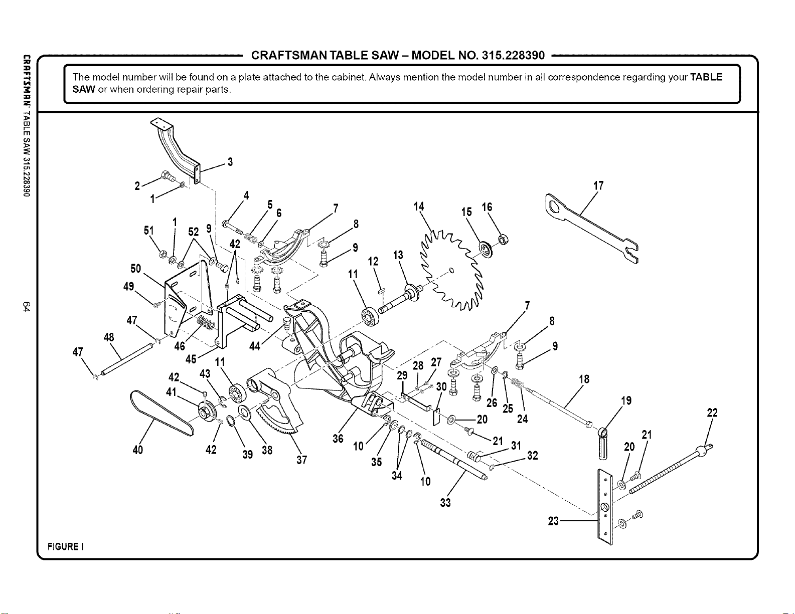
+
-4
Ir'--
I1"1
)i>
co
o
Ob
4_
CRAFTSMAN TABLE SAW- MODEL NO. 315.228390 •
I he model number will be found on a plate attached to the cabinet. Always mention the model number in all correspondence regarding your TABLE I
SAW or when ordering repair parts.
J
47
FIGUREI
48
50
49
47
11
42 43
40 42 39 38
4
5 6 7 14 15 16
36
10
37
12
35
13
34
10
33
24
31
17
18
23--
19
22
20 21
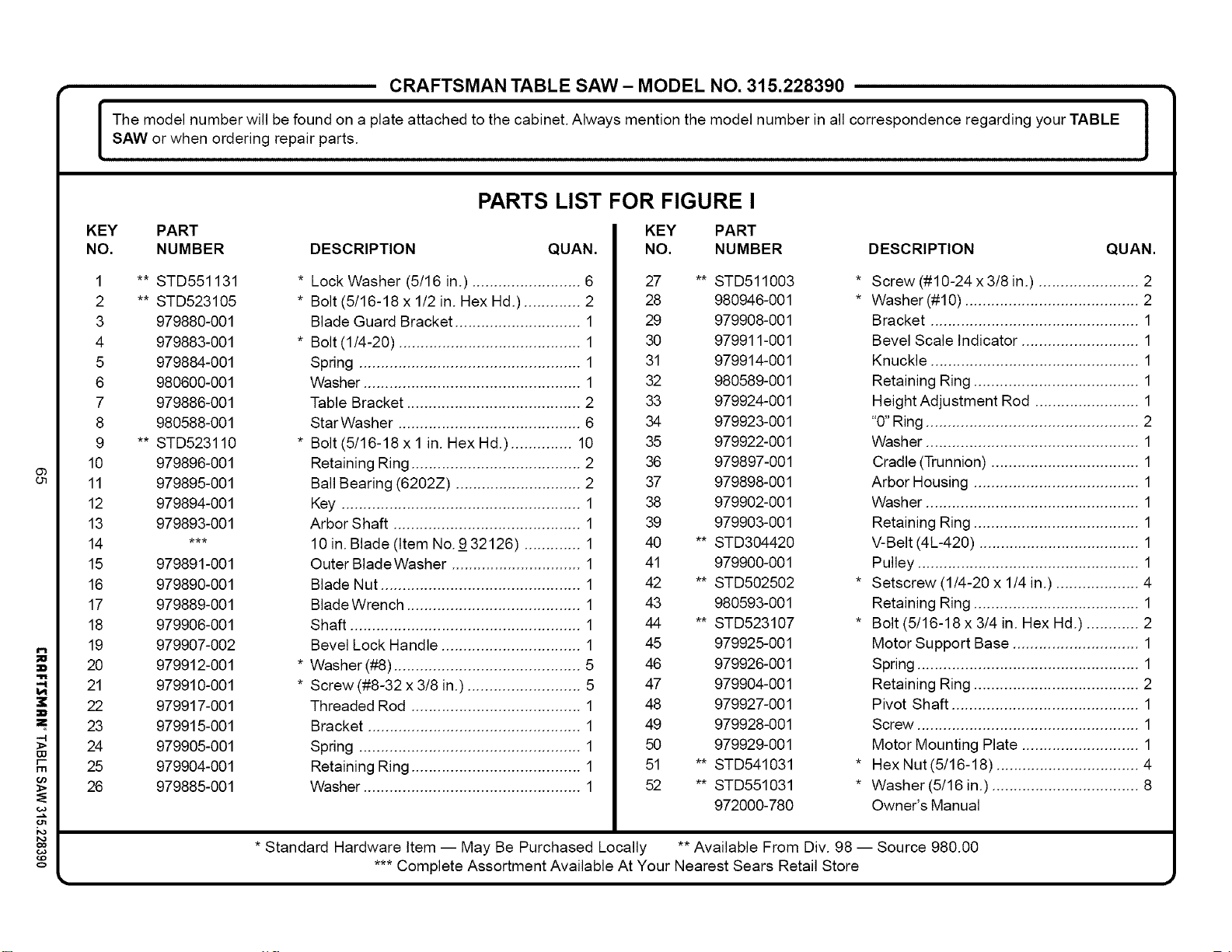
P,,
i
W
r-"
rrl
o
CRAFTSMAN TABLE SAW- MODEL NO. 315.228390 •
I he model number will be found on a plate attached to the cabinet. Always mention the model number in all correspondence regarding your TABLE
SAW or when ordering repair parts.
J
PARTS LIST FOR FIGURE I
KEY PART
NO. NUMBER DESCRIPTION QUAN.
1 ** STD551131
2 ** STD523105
3 979880-001
4 979883-001
5 979884-001
6 980600-001
7 979886-001
8 980588-001
9 ** STD523110
10 979896-001
11 979895-001
12 979894-001
13 979893-001
14 ***
15 979891-001
16 979890-001
17 979889-001
18 979906-001
19 979907-002
20 979912-001
21 979910-001
22 979917-001
23 979915-001
24 979905-001
25 979904-001
26 979885-001
* Lock Washer (5/16 in.) ......................... 6
* Bolt (5/16-18 x 1/2 in. Hex Hd.) ............. 2
Blade Guard Bracket ............................. 1
* Bolt (1/4-20) .......................................... 1
Spring ................................................... 1
Washer .................................................. 1
Table Bracket ........................................ 2
StarWasher .......................................... 6
* Bolt (5/16-18 x 1 in. Hex Hd.) .............. 10
Retaining Ring ....................................... 2
Ball Bearing (6202Z) ............................. 2
Key ....................................................... 1
Arbor Shaft ........................................... 1
10 in. Blade (Item No.9 32126) ............. 1
Outer BladeWasher .............................. 1
Blade Nut .............................................. 1
Blade Wrench ........................................ 1
Shaft ..................................................... 1
Bevel Lock Handle ................................ 1
* Washer (#8) ........................................... 5
* Screw (#8-32 x 3/8 in.) .......................... 5
Threaded Rod ....................................... 1
Bracket ................................................. 1
Spring ................................................... 1
Retaining Ring ....................................... 1
Washer .................................................. 1
KEY PART
NO. NUMBER DESCRIPTION QUAN.
27 ** STD511003
28 980946-001
29 979908-001
30 979911-001
31 979914-001
32 980589-001
33 979924-001
34 979923-001
35 979922-001
36 979897-001
37 979898-001
38 979902-001
39 979903-001
40 ** STD304420
41 979900-001
42 ** STD502502
43 980593-001
44 ** STD523107
45 979925-001
46 979926-001
47 979904-001
48 979927-001
49 979928-001
50 979929-001
51 ** STD541031
52 ** STD551031
972000-780
* Screw (#10-24 x 3/8 in.) ....................... 2
* Washer (#10) ........................................ 2
Bracket ................................................ 1
Bevel Scale Indicator ........................... 1
Knuckle ................................................ 1
Retaining Ring ...................................... 1
Height Adjustment Rod ........................ 1
"0" Ring ................................................. 2
Washer ................................................. 1
Cradle (Trunnion) .................................. 1
Arbor Housing ...................................... 1
Washer ................................................. 1
Retaining Ring ...................................... 1
V-Belt (4L-420) ..................................... 1
Pulley ................................................... 1
* Setscrew (1/4-20 x 1/4 in.) ................... 4
Retaining Ring ...................................... 1
* Bolt (5/16-18 x 3/4 in. Hex Hd.) ............ 2
Motor Support Base ............................. 1
Spring ................................................... 1
Retaining Ring ...................................... 2
Pivot Shaft ........................................... 1
Screw ................................................... 1
Motor Mounting Plate ........................... 1
* Hex Nut (5/16-18) ................................. 4
* Washer(5/16 in.) .................................. 8
Owner's Manual
* Standard Hardware Item -- May Be Purchased Locally ** Available From Div. 98 -- Source 980.00
*** Complete Assortment Available At Your Nearest Sears Retail Store

Parapedirserviciode reparaciCnadomicilio, AuCanadapourserviceenfran_;ais:
y paraordenarpiezasconentregaadomicilio: 1-877-LE-FOYER sM
1-888-SU-HOGAR sM (1-877-533-6937)
(1-888-784-6427) _
® Registered Trademark / TMTrademark of Sears, Roebuck and Co.
® Sears, Roebuck and Co ® Marca Registrada / 7M Marca de Fabrica de Sears, Roebuck and Co

