WIRE
D
CONTROL F
OR
AIR CONDITIONER
Thank you very much for purchasing our product.
Before using your unit, please read this manual carefully and keep it for future reference.
INSTALLATION&
OWNER’ S MANUAL


● This manual gives detailed description of the precautions
that should be brought to your attention during operation.
● In order to ensure correct service of the wired control
please read this manual carefully before using the unit.
● For convenience of future reference, keep this manual
after reading it.

CONTENTS
1. SAFETY PRECAUTION.............................................................................. 1
2. INSTALLATION ACCESSORY.................................................................... 2
3. INSTALLATION METHOD...........................................................................4
4. SPECIFICATION.......................................................................................10
5. FEATURE AND FUNCTION OF THE WIRED CONTROL........................11
6. NAME ON THE LCD OF THE WIRE CONTROL....................................12
7. NAME OF BUTTON ON THE WIRE CONTROL.......................................13
8. PREPARATORY OPERATION..................................................................15
9. OPERATION..............................................................................................16
10. TIMER FUNCTIONS................................................................................21
11. WEEKLY TIMER......................................................................................24
12. FAULT ALARM HANDING.......................................................................30
13.TECHNICAL INDICATION AND REQUIREMENT ...................................30
1
Read the safety precautions carefully before installing the unit.
Stated below are important safety issues that must be obeyed.
Means improper handling may lead to personal death or severe injury.
Means improper handling may lead to personal injury or property loss.
WARNING
CAUTION
Please entrust the distributor or professionals to install the unit.
Installation by other persons may lead to imperfect installation, lectric shock or re.
Adhere to this installation manual.
Imporper installation may lead to electric shock or re.
Reinstallation must be performed by professionals.
Improper installation may lead to electric shock or re.
WARNING
Do not install the unit in a place vulnerable to leakage of ammable gases.Once
ammable gases are leaked and left around the wire control, re may occure.
Do not operate with wet hands or let water enter the wire control. Otherwise,
electric shock may occur.
The wiring should adapt to the wire control current. Otherwise, electric leakage or
heating may occur and result in re.
The specied cables shall be applied in the wiring. No external force may be applied
to the terminal. Otherwise, wire cut and heating may occur and result in re.
NOTE
Do not uninstall the unit randomly.
Random uninstalling may lead to abnormal operation, heating or re of the air condition.
1
2
3
4
1. SAFETY PRECAUTION

2
2. INSTALLATION ACCESSORY
Don’t install at the place where cover with heavy oil, vapor or sulfureted gas,
otherwise, this product would be deformed that would lead to system malfunction.
Select the installation location
Preparation before installation
1. Please conrm that all the following parts you have been supply.
2. Prepare the following assemblies on the site.
The connective wires group-1
1
2
3
4
5
3
2
M4X20 (For Mounting on the Wall)
M4X25 (For Mounting on switch box)
1
2
1
6
7
3
2
1
No. Name Qty. Remarks
Wire control
Installation and owner’s manual
For Mounting on the Wall
Switch box
Wiring Tube(Insulating
Sleeve and Tightening
Screw)
Qty.(embeded
into wall)
Plastic screw bars
Screws
Wall plugs
For fixing on switch box
No.
Name
Remarks
Specification
(only for reference)
Screws
1
1
1
Optional
Connect to mainboard
The connective wires group-2
8
1
Battery
9
1

3
2. INSTALLATION ACCESSORY
Precaution of install the wire control
1. This manual provides the installation method of wire control. Please refer to the
wiring diagram of this installation manual to wire the wire control with indoor unit.
2. The wire control working in low voltage loop circuit. Forbid to directly contact the
cable of 220Vcommercial electricity or of 380V high voltage, and don’t wire this kind
of wire in the said loop; wiring clearance between congured tubes should at the
range of 300~500 or above.
3. The Shielded wire of the wire control must be grounded reliable.
4. Upon nish the wire control connection, do not employed tramegger to detect the
insulation.
5. The connective cable of wire control should not be longer than 20 meters.
Applicable to 12V only
4
3. INSTALLATION METHOD
Fig 3-1
Fig 3-2(a)
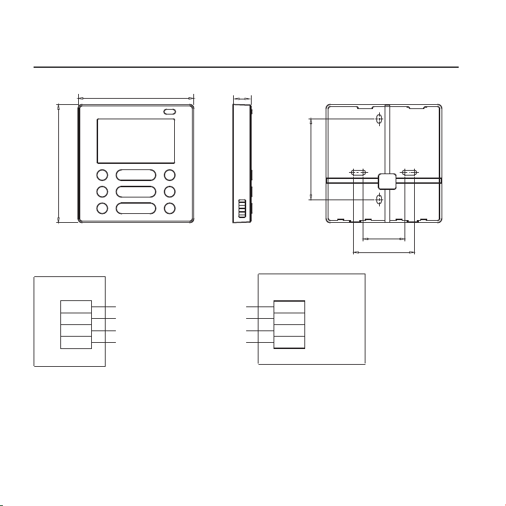
1.Wired remote control structure size gure
2.Wiring Principle Sketch:
red
black
yellow
brown
red
black
yellow
brown
Insert of the
mainboard CN40
Wire control
Indoor unit mainboard
4-Core Shield Cable, the length
is decided by installation
-----------------------------------
-----------------------------------
-----------------------------------
-----------------------------------
120
122
18.5
83.5
46
62

5
3. INSTALLATION METHOD
Fig 3-4
Connect the female joint of wires group from the mainboard with the male joint of
connective wires group. (See Fig.3-3)
Please connect the other side of connective wires group with the male joint of
wires group leads from wire control. (See Fig.3-3)
Fig 3-3
Mainboard
4-core shielding wire
3.Wiring figure
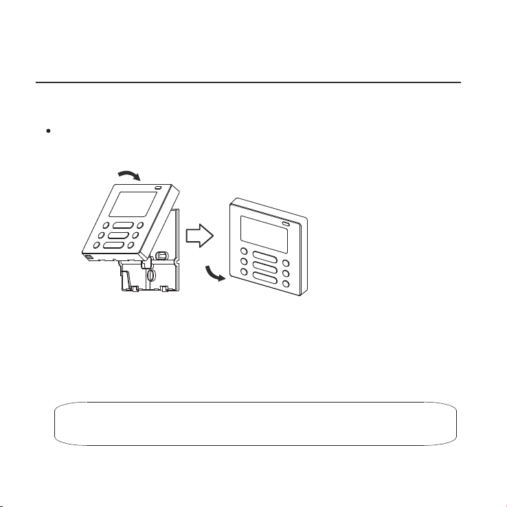
4.Remove the upper part of wire control
The connective wires group-1
The connective wires group-2
CN40
Insert a slot screwdriver into the slots in the lower
part of the wire control (2 places), and remove
the upper part of the wire control. (Fig.3-4)
Slots
NOTICE
The PCB is mounted in the upper part of the wire
control. Be careful not to damage the board
with the slot screwdriver.

6
Fig 3-5
Fig 3-6
3. INSTALLATION METHOD
Switch box
Back plate
For exposed mounting, fasten the back plate on the wall with the 3 screws (M4×20)
and plugs. (Fig.3-5)
For ush-mounting, fasten the back plate on the switch box with 2 screws (M4×25) and
fasten it on the wall with 1 screw (M4×20). (Fig.3-6)
5. Fasten the back plate of the wire control
Back plate
Screws (M4×20)
Screw (M4×20)
Screws (M4×25)
NOTICE
Put on a at surface. Be careful not to distort the back plate of the wire control
by overtightening the mounting screws.
7
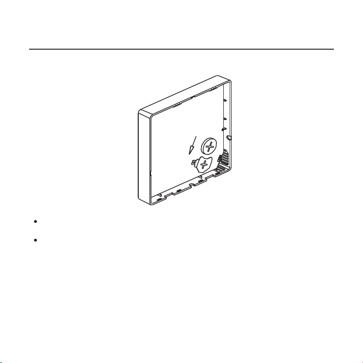
Put the battery into the installationsite and make sure the positive side of the battery
is in accordance with the positive side of installationsite.(See Fig.3-7)
Please set the time corrected on the rst time operation. Batteries in the wire
control can timing under power failure which ensure the time keep right. When
the power restores, if the time displayed is not correct, it means the battery is dead
and replace the battery.
Fig 3-7
3. INSTALLATION METHOD
6. Battery installation
8
Fig 3-8
Fig 3-9
Fig 3-10
3. INSTALLATION METHOD
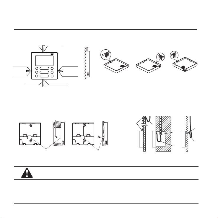
7. Wiring
Cutting place of top
side wire outlet
Cutting place of left
side wire outlet
Cutting place of right
side wire outlet
A. For wiring in the slot, four outletting positions.
There are three need cutting.
Diameter of wall hole:Ø 3/4”
Embedded switch
box wiring
B.Shielded wiring
Wiring
hole
Wiring through the wall
Wall hole and wiring hole
Putty
Putty
Putty
Trap
Trap
Trap
CAUTION
Avoid the water enter into the wired remote control, use trap and putty to seal the
connectors of wires during wiring installation. (Fig.3-10)
When under installation, reserve certain length of the connecting wire for convenient
to take down the wired remote control while during maintenance.
Top side
wire outlet
Left side
wire outlet
Right side
wire outlet
Bottom side
wire outlet
Line groove
Line groove
Line groove
Line groove
9
Fig 3-11
3. INSTALLATION METHOD
All the pictures in this manual are for explanation purpose only.
Your wire control may be slightly dierent .The actual shape shall prevail.
8.Reattach the upper part of the wire control
After adjusting the upper case and then buckle the upper case; avoid clamping the
wiring during installation. (
Fig 3-1
1)

4. SPECIFICATION
DC 12V
23~110℉ (-5~43℃)
RH40%~RH90%
Input voltage
Ambient temperature
Ambient humidity
10
POWER
MODE
FAN SPEED
TIMER SWING SWING FOLLOW ME
DELAY/DAY OFF CONFIRM BACK COPY
11
5. FEATURE AND FUNCTION OF THE WIRED
CONTROL
Function:
Mode: choose Auto-Cool-Dry- Heat -Fan
Fan speed: Auto/Low/Med/High speed
UP-DOWN swing & LEFT-RIGHT swing(on
some models)
Timer ON/OFF
Temp setting
Weekly timer
Follow Me
Child Lock
LCD display
Clock
Infrared remote receiver (on some models)
Faceplate function (on some models)
Feature:
LCD display.
Room temperature display.
Weekly Timer.
4-way wire layout design, no raised part
at backside, more convenient to place
the wires and install the device.
Malfunction code display: it can display
the error code, helpful for service.
Dimension:
H×W×D (in/mm)
4.8x4.7x0.72/122×120×18.5
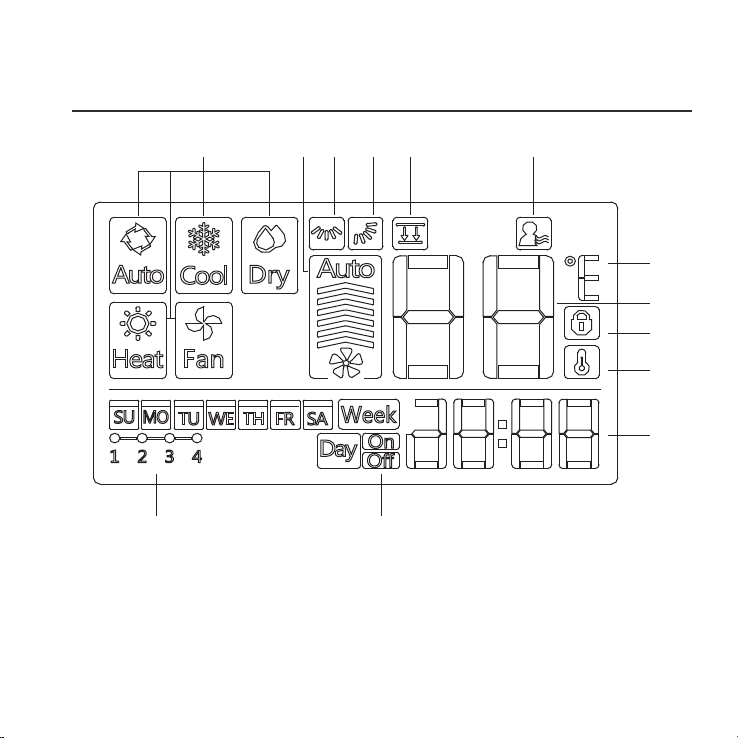
6. NAME ON THE LCD OF THE WIRE CONTROLER
1 Operation mode indication
2 Fan speed indication
3 Left-right swing indication
4 Up-down swing indication
5 Faceplate function indication
6 Follow me function indication
7 F° / C° indication
1 2 3 4 5 6
7
8
9
10
11
13 12
8 Temperature display
9 Lock indication
10 Room temperature indication
11 Clock display
12 On/O timer
13 Timer display
12
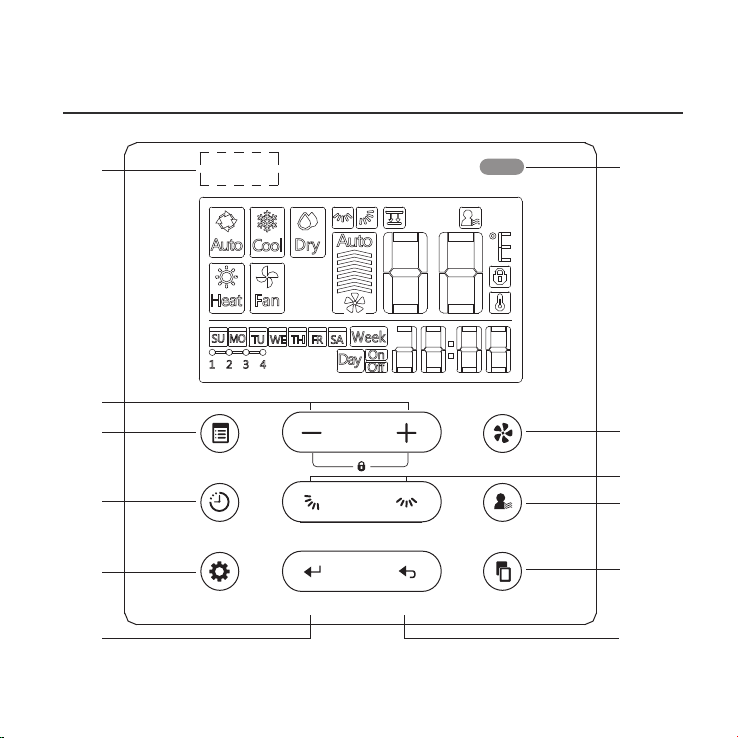
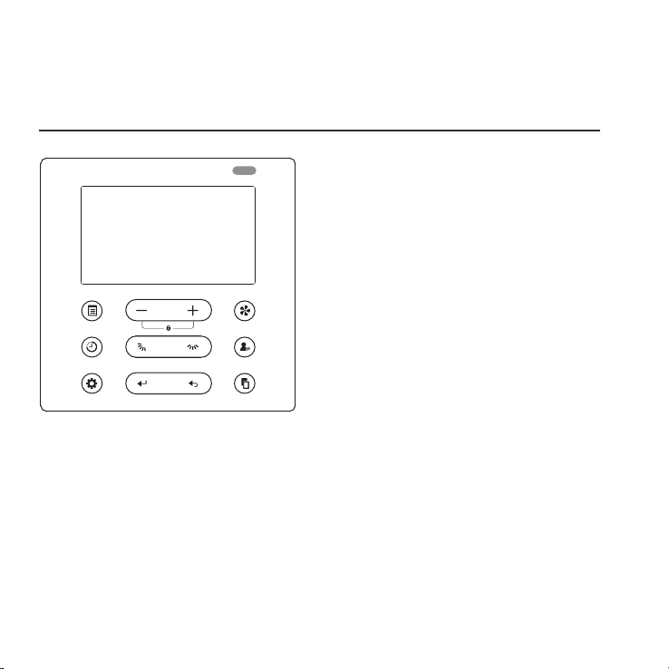
7. NAME OF THE BUTTON ON THE WIRE CONTROL
1
2
3
4
5 6
7
8
9
10
11
12
POWER
MODE
FAN SPEED
TIMER SWING SWING FOLLOW ME
DELAY/DAY OFF CONFIRM BACK COPY
13
13

1 POWER button
2 MODE button
3 Adjust button
4 FAN SPEED button
5 UP-DOWN airow direction and swing button
6 LEFT-RIGHT swing button
7 FOLLOW ME button
8 TIMER button
9 DELAY/DAY OFF button
10 CONFIRM button
11 BACK button
12 COPY button
13 Infrared remote receiver (on some models)
7. NAME OF THE BUTTON ON THE WIRE CONTROL
14
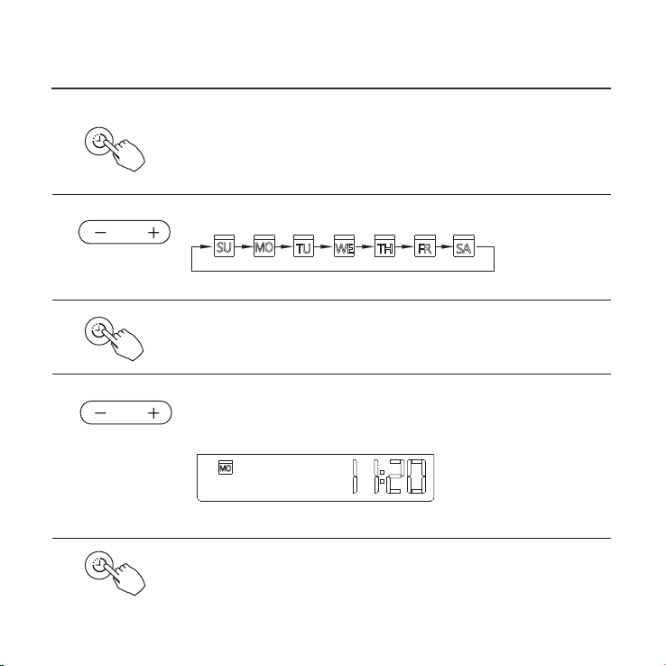
8. PREPARATORY OPERATION
Press the TIMER button for 3 seconds or more.
The timer display will ash.
Press the button “+” or “-” to set the current time.
Press repeatedly to adjust the current time in 1-minute increments.
Press and hold to adjust the current time continuous.
ex.Monday AM 11:20
1
2
3
4
5
Press the button “ + ” or “ - ” to set the date. The selected
date will ash.
The date setting is nished and the time setting is prepared after pressing
TIMER button or there is no pressing button in 10 seconds.
The setting is done after pressing TIMER button or there is no
pressing button in 10 seconds.
Set the current day and time
TIMER
TIMER
TIMER
15
9. OPERATION
To start/stop operation
Press the POWER button.
Operation lamp
Air conditioner ON :Lit brightly
Air conditioner OFF:Not lit
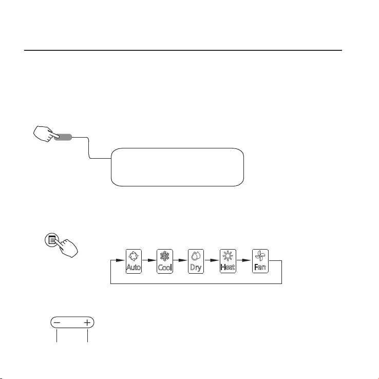
To set the operation mode
Press the MODE button to set the operation mode.
(Heat function is invalid for cool only type unit)
Room temperature setting
Press the button“ + ”or “ - ” to set the room temperature.
Indoor Setting Temperature Range :
17~30℃(62~86℉/62~88℉(Depending on models)).
Lower Raise
Operation mode setting
POWER
MODE
16
Remote signal receiving function
The wired remote control can be a remote signal receiving device, you can use the
wireless remote control to control the air-conditioner through the wired remote
control when the system have been powered on.
9. OPERATION
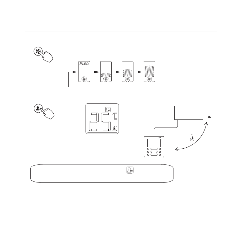
Fan speed setting
Press the FAN SPEED button to set the fan speed.
(This button is unavailable when in the mode of Auto or Dry)
Room temperature sensor selection
Indoor Unit
Press the FOLLOW ME button to select whether
the room temperature is detected at the indoor
unit or the wire control.
When the Follow me function indication appears,
the room temperature is detected at the wire control.
FAN SPEED
FOLLOW ME
17
9. OPERATION
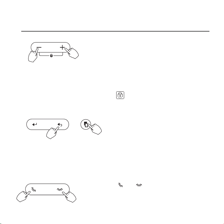
Child lock function
Press the button “+” and “-” simultaneously for 3 seconds to activate
the child lock function and lock all buttons on the wire control.
Press the buttons again for 3 seconds to deactivate the child lock function.
When the child lock function is activated,the mark appears.
keypad tone setting
Press the button “BACK” and “COPY” simultaneously for 3 seconds to
close the keypad tone.
Press the buttons again for 3 seconds to open the keypad tone.
BACK COPY
18
°C & °F scale selection (on some models)
Press and hold and buttons together
for 3 seconds will alternate the temperature display
between the
℃&℉
scale.
SWING SWING

9. OPERATION
Faceplate function (on some models)
1.When the unit is o,Press the MODE button long to activate the faceplate
function.The mark will ash.
2. Press the button “+” and “-” to control the lift and drop of the faceplate.
Pressing the “+” button can stop the faceplate,while it is dropping.
Pressing the “-” button can stop the faceplate,while it is lifting.
The F2 mark appears when
the faceplate is adjusted.
MODE
Left-Right swing (on some models)
Press the button to start Left-Right swing function.
Press it again to stop.
When the Left-Right swing function is activated, the mark appears.
(Not applicable to all the models)
19
SWINGSWING

9. OPERATION
Up-Down airflow direction and swing (on some models)
1.Press the button every time, the louver swings 6 degrees.
2.Press and hold the button for 2 seconds,it turns into up-down swing mode,
press ti again to stop.
When the Up-Down swing function is activated,the mark appears. (Not applicable
to all the models)
The operation can refer to the following instructions for the unit with four Up-Down
louvers can be operated individually.
-0
-1
-2
-3
-4
1.Press the button to activate the Up-Down adjusting
louver function.
The mark will ash.(Not applicable to all the models)
2.Pressing the button “+” or“-” can select the movement
of four louvers.Each time you push the button,the wire
control select in a sequence that goes from:(the icon
means the four louvers move at the same time.)
3. And then use button to adjust the Up-Down airow direction of the selected
louver.
-0
20
SWING SWING
SWING
SWING
Use button to adjust the Up-down airow direction.
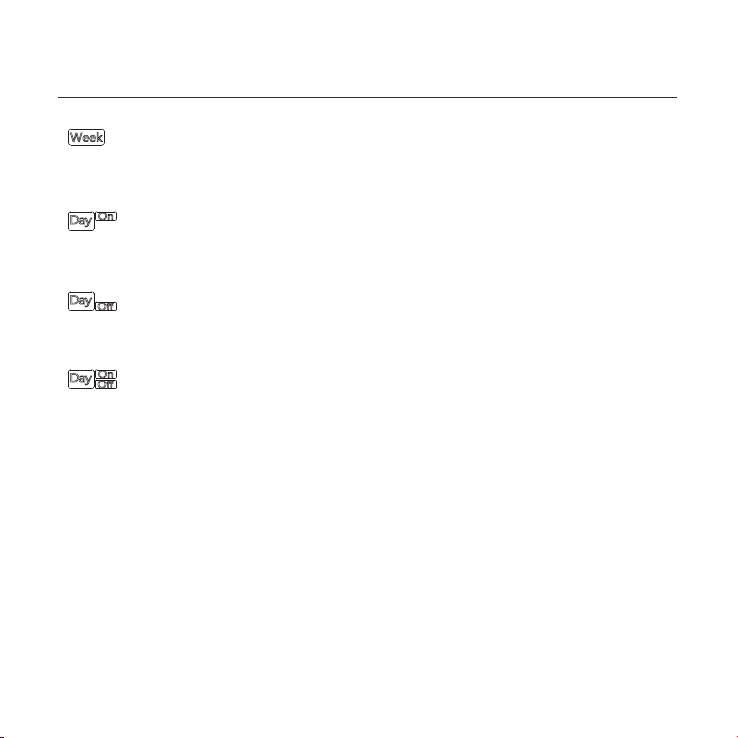
10. TIMER FUNCTIONS
WEEKLY timer
Use this timer function to set operating times for each day of the week.
On timer
Use this timer function to start air conditioner operation.The timer operates
and air conditioner operation starts after the time has passed.
O timer
Use this timer function to stop air conditioner operation.The timer operates
and air conditioner operation stops after the time has passed.
On and O timer
Use this timer function to start and stop air conditioner operation.The timer
operates and air conditioner operation starts and stops after the time has
passed.
21
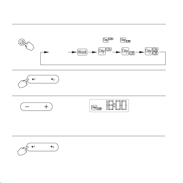
10. TIMER FUNCTIONS
To set the On or Off TIMER
Press the TIMER button to select the or .
No display
1
2
Press the CONFIRM button and the Clock display
is ashing.
Press the CONFIRM button again to nish the settings.
3
Press the button “ + ” or “ - ” to set the time. After the time is set,
the timer will start or stop automatically.
ex.O timer set at PM 6:00
4
TIMER
CONFIRM
CONFIRM
22
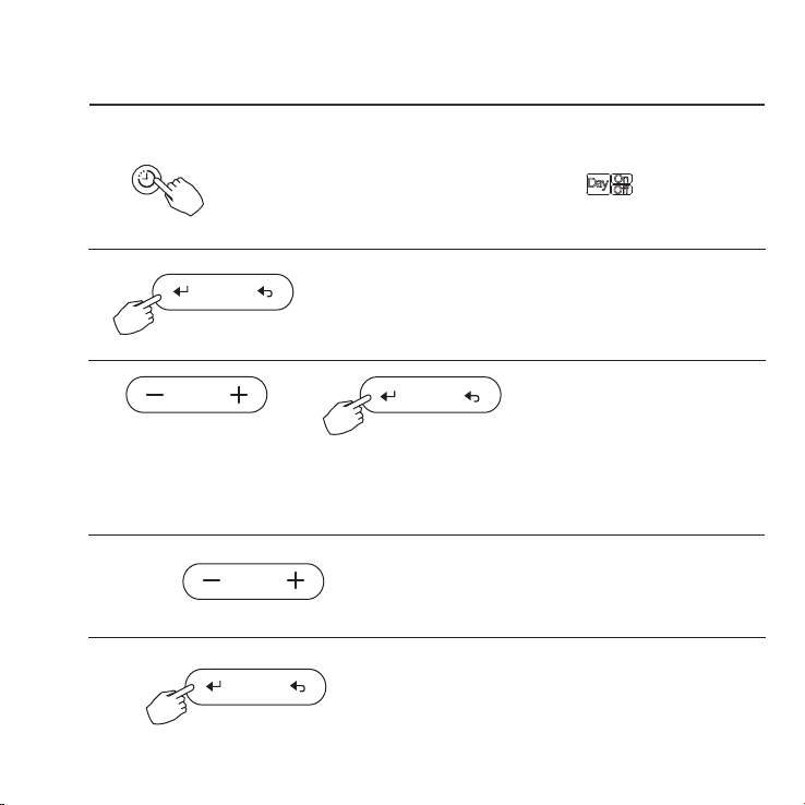
10. TIMER FUNCTIONS
Press the CONFIRM button to nish the settings.
To set the On and Off TIMER
Press the TIMER button to select the .
1
2
Press the CONFIRM button and the Clock display is ashing.
3
Press the button “ + ” or “ - ” to set the time of On timer,and then press the
CONFIRM button to conrm the setting.
4
Press the button “ + ” or “ - ” to set the time of O
timer.
5
TIMER
CONFIRM
23
CONFIRM
CONFIRM
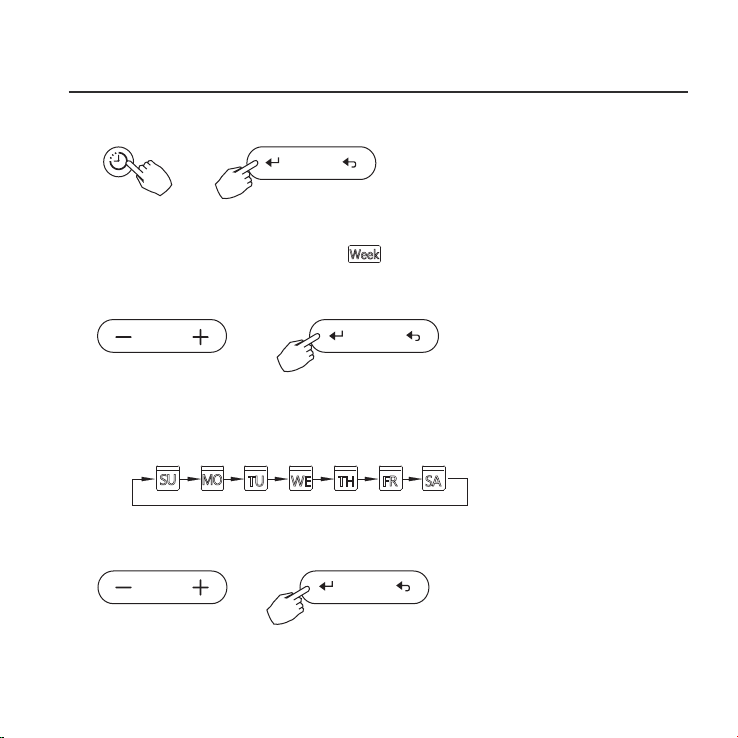
11. WEEKLY TIMER
Press the button “ + ” or “ - ” to set the time of O
timer.
Weekly timer setting
Press the TIMER button to select the and then press the CONFIRM button
to conrm.
1
Press the button “ + ” or “ - ” to select the day of the week.and then press the
CONFIRM button to conrm the setting.
2
Day of the week setting
TIMER
CONFIRM
Press the button “ + ” or “ - ” to set the time of On timer.and then press the
CONFIRM button to conrm the setting.
ON timer setting of timer setting 1
3
CONFIRM
24
CONFIRM
11. WEEKLY TIMER
ex.Tuesday time scale 1
Up to 4 timer settings can be saved for each day of the week.It is
conventent if the WEEKLY TIMER is set according to the user’s life style.
Dierent timer settings can be setted by repeating step 3 to 4.
Other days in one week can be setted by repeating step 2 to 5.
NOTE: The weekly timer setting can be returned to the previous step by pressing
BACK button.
The time of timer setting can be delete by pressing DAY OFF botton
The current setting will be restored and withdrawn the weekly timer setting
automatically when there is no operation for 30 seconds.
4
Off timer setting of timer setting 1
Press the button “ + ” or “ - ” to set the time of O timer.and then press
the Conrm button to conrm the setting.
5
6
ex.Tuesday time scale 1
25
CONFIRM
POWER
11. WEEKLY TIMER
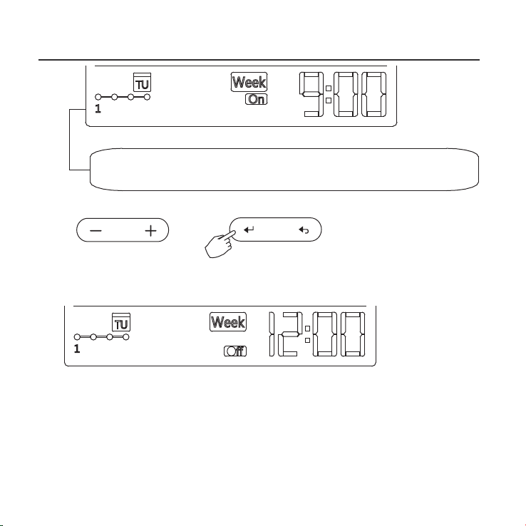
To activate WEEKLY TIMER operation
WEEKLY timer operation
Press the TIMER button while is displayed on the LCD.
ex.
TIMER
TIMER
To deactivate WEEKLY TIMER operation
Press the TIMER button while is disappear from the LCD.
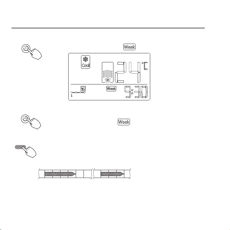
● To turn off the air conditioner during the weekly timer
1. If press the POWER button once and quickly , the air conditioner will turn o
temporarily. And the air conditioner will turn on automatically until the time of
On timer.
ON OFF ON OFF
8:00 12:00 14:00 17:0010:00
ex. If press the POWER button once and quickly at 10:00, The air conditioner
will turn on at 14:00.
2. When press the POWER button for 2 seconds , the air conditioner will
turn o completely.
26
11. WEEKLY TIMER
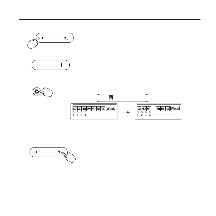
To set the DAY OFF (for a holiday)
During the weekly timer, press the CONFIRM
button.
1
Press the button “ + ” or “ - ” to select the day in this
week .
2
CONFIRM
Press the BACK button to back to the weekly timer.
Press the DAY OFF button to set the DAY OFF.
3
5
To cancel:Follow the same procedures as those for setup.
4
ex.The DAY OFF is set for Wednesday
The DAY OFF can be setted for other days by repeating
the steps 2 and 3.
The mark is hidden
Notes:
The DA Y OFF setting is cancelled automatically after the set day has passed.
DELAY/DAY OFF
BACK
27
11. WEEKLY TIMER
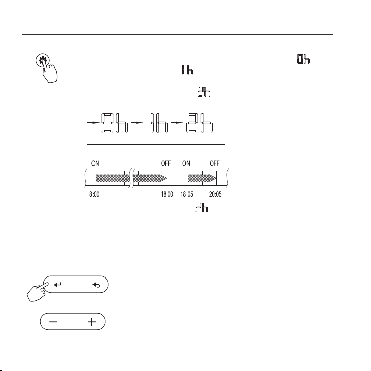
DELAY function
DELAY/DAY OFF
During the weekly timer, pressing the DELAY button once,display " ".
Press this button twice, display " " and wait 3 seconds to conrm.
It means the unit will override 1 hours;
Press this button three times,display " " and wait 3 seconds to conrm.
It means the unit will override 2 hours;
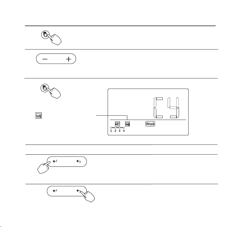
Copy out the setting in one day into the other day.
During the weekly timer, press the CONFIRM button.
1
2
Press the button “ + ” or “ - ” to select the day to copy from.
CONFIRM
A reservation made once can be copied to another day of the week.
The whole reservation of the selected day of the week will be copied.
The eective use of the copy mode ensures ease of making reservations.
28
ex. If press the DELAY button to select “ ” at 18:05 ,
The air conditioner will delay to turn o at 20:05.
11. WEEKLY TIMER
Press the COPY button,the letter “CY” will be
shown on the LCD.
3
4
Press the button “ + ” or “ - ” to select the day
to copy to.
COPY
Press the Conrm button to conrm the settings.
Press the Back button to back to the weekly timer.
5
Press the COPY button to conrm .
Other days can be copied by repeating step 4 and 5.
ex. Copy the setting of Monday to Wednesday
The mark ashes quickly
6
7
8
COPY
CONFIRM
BACK
29
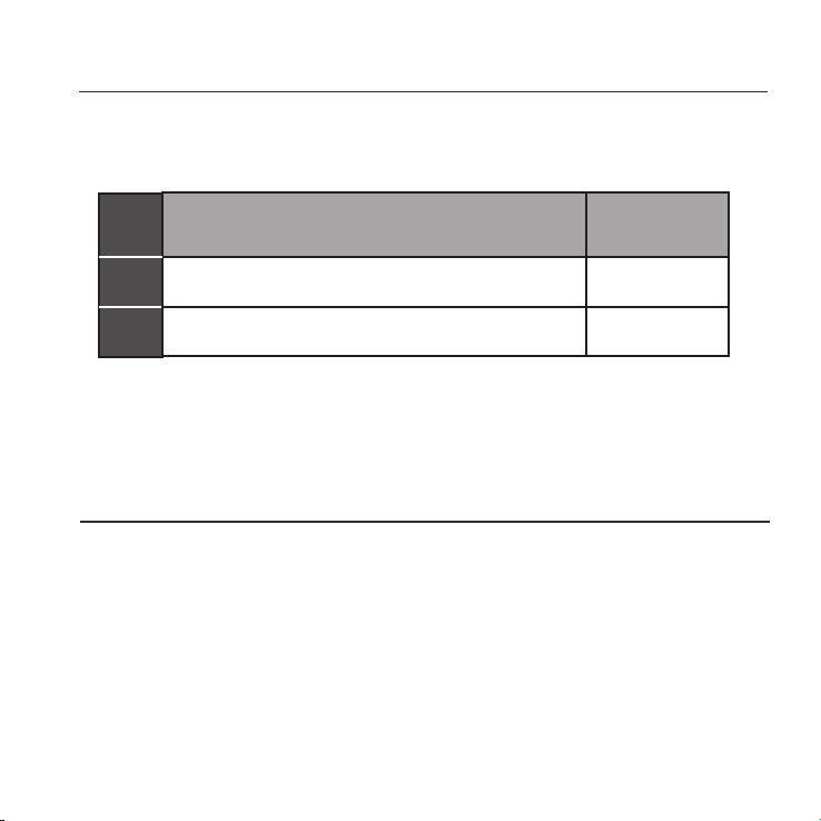
12. FAULT ALARM HANDING
MALFU NCTION & PROTECTION DEFINE
DISPLAY
F0
F1
DIGITAL TUBE
NO.
1
2
The faceplate is abnormal
Error of communication between wire control
If the system does not properly operate except the above mentioned cases or the above
mentioned malfunctions is evident, investigate the system according to the following
procedures.
Please check the error display of indoor unit and read <<OWNER'S MANUAL>>
if other error code appears.
and indoor unit
13.TECHNICAL INDICATION AND REQUIREMENT
EMC and EMI comply with the CE certication requirements.
30

The design and specications are subject to change without prior notice
for product improvement.Consult with the sales agency or manufacturer
for details