PRO.FORM" '"
PRO.FORAT "
LOW PROFILE TREAI_M_!LL
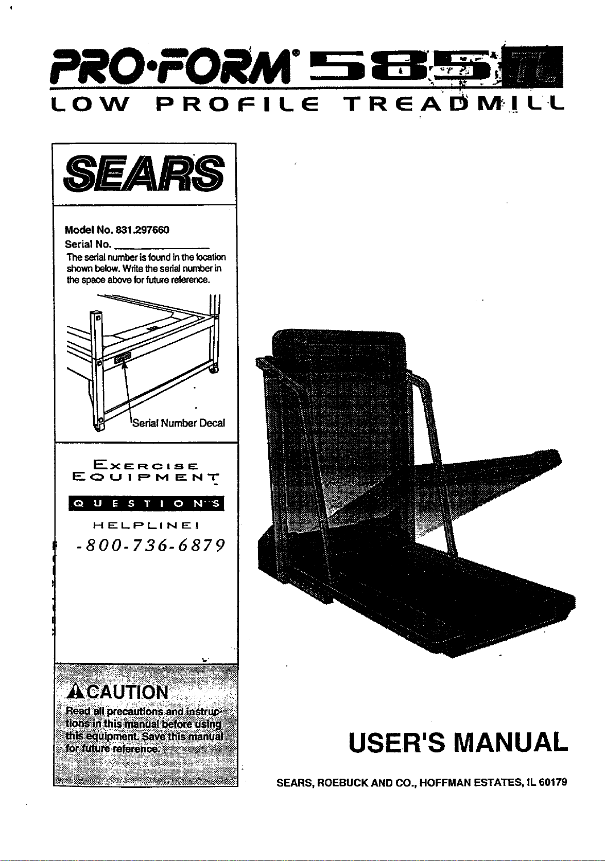
Model No. 831.297660
Serial No.
The serialnumberisfoundinthelocation
shownbelow.Writethesedalnumberin
thespaceaboveforfuturereference.
I_"X_-RC i == i=-
EQUIPMENT
HELPLINE!
-800-736-6879
USER'S MANUAL
SEARS, ROEBUCK AND CO., HOFFMAN ESTATES, IL 60179
TABLE OF CONTENTS
FULL 90 DAY WARRANTY ......................... . ; ............. :. :,....................... ,2
IMPORTANT PRECAUTIONS ................................................................
BEFORE YOU BEGIN ......................................... +.............................. 5
ASSEMBLY ................................................. ; ............................. 6
OPERATION AND ADJUSTMENT ............................................................. 7
HOW TO FOLD AND MOVE THE TREADMILL ................... ; 10
• • • +.ooo.oo+oo°.°°ooo.o°oo-°o°
TROUBLE-SHOOTING ..................................................................... 12
CONDITIONING GUIDELINES .................................. , ............................ 14
ORDERING REPLACEMENT PARTS .................................................. Back Cover
Note: A n EXPLODED DRAWING, and a PART LIST are attached to the center of this manual. Please save them
for future reference.
FULL 90 DAY WARRANTY
For 90 days from the date of purchase, if failure occurs due to defect in material or workmanship in this
SEARS TREADMILL EXERCISER, contact the nearest SEARS Service Center throughout the United
States and SEARS willrepair or replace the TREADMILL EXERCISER, free of charge.
This warranty does not applywhen the TREADMILL EXERCISER is used commerciallyor for rental pur-
poses.
This warranty gives you specific legal rights,and you may also have other rights whichvary from state
to state.
SEARS, ROEBUCK AND CO., DEPT. 817WA, HOFFMANESTATES, IL 60179
2

IMPORTANT PRECAUTIONS
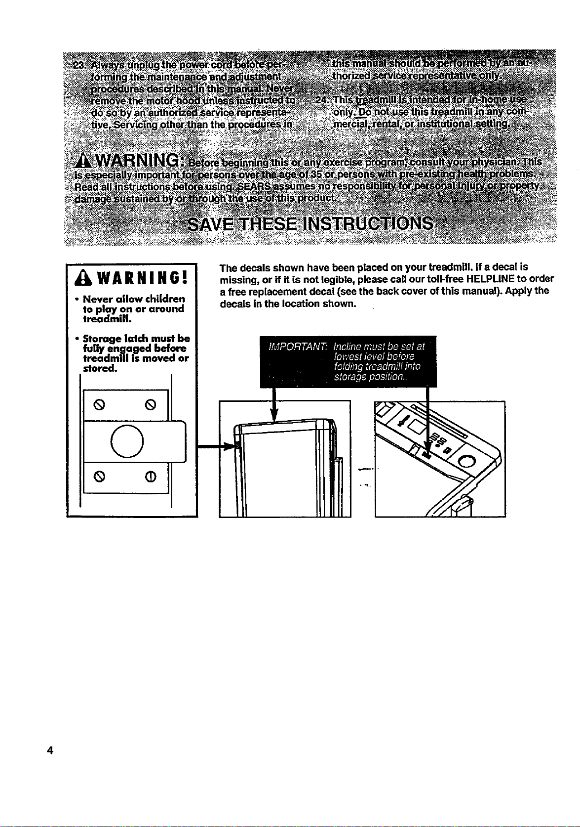
XkWARNIHG!
• Never allow children
to ploy on or around
treadmill.
• Storage latch must be
fully engaged before
treadmill is moved or
stored.
° °II
©1
m
The decals shown have been placed on your treadmill. If a decal is
missing, or if it is not legible, please call our toll-free HELPLINE to order
a free replacement decal (see the back cover of this manual). Apply the
decals in the location shown.
41,
4
.i
BEFORE YOU BEGIN
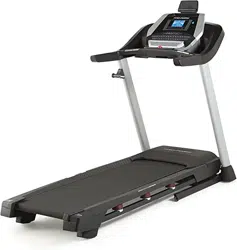
Thank you for selecting the PROFORM" 585 TL treod-
mill.The 585 TL treadmill blends advanced technology
with innovative design to let you enjoy an excellent
form of cardiovascular exercise in the convenience
and privacy of your home.
For your benefit, read this manual carefully before
using the treadmill. Ifyou have additional questions,
please call our toll-free HELPMNE at 1-800-736-6879,
Monday through Saturday, 7 a.m. until 7 p.m. Central
Time (excluding Iiol|oays). _,_elp us ,_sslstyou,
please note the product model number a.qdsedal num-
ber before ceiling. The model number of the treadmill
is831.297660. The serial number can be found on a
decal attached to the treadmill (see the front cover of
this manual for the location).
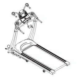
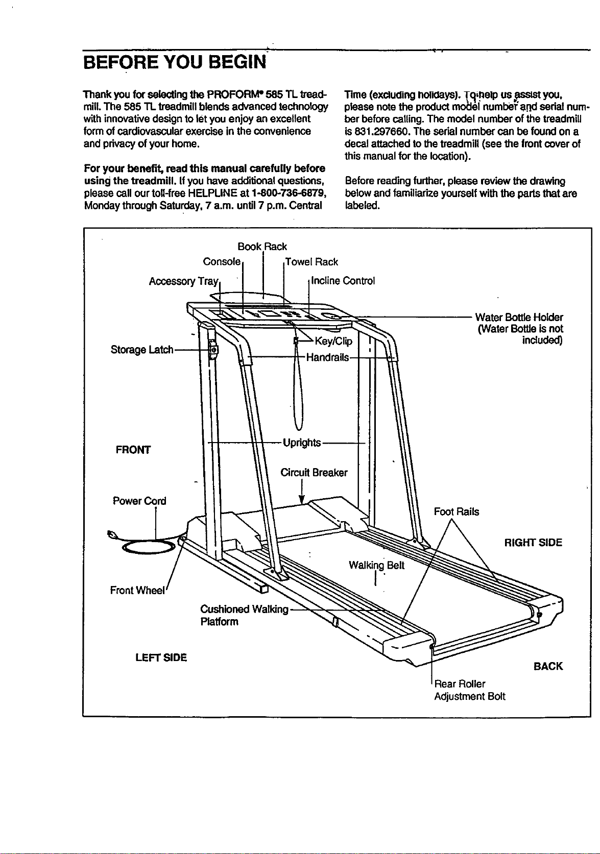
Before reading further,please review the drawing
below and familiarize yourself with the parts that are
labeled.
Book Rack
Console Towel Rack
Accessor InclineControl
Storag,
FRONT
PowerCord
Circuit Breaker
Foot Rails
Water BottleHolder
(Water Bottle isnot
included)
Walkii_ Beit
RIGHT SIDE
Platform
LEFT SIDE
Rear Roller
Adjustment Bolt
BACK
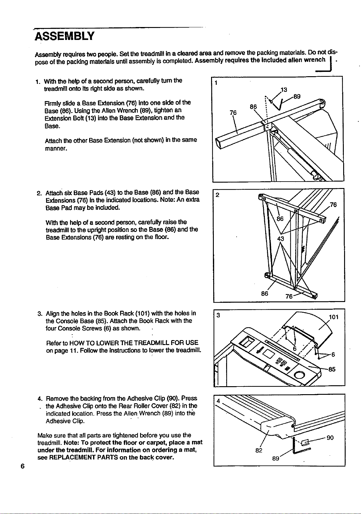
ASSEMBLY
Assembly requires two people. Sat the treadmill in a cleared area and remove the packing materials. Do not dis-
pose ofthe packing materials untilassembly is completed. Assembly requires the Included alien wrench _ .
..._/
1. W'dhthe help of a second person, carefully turn the
treadmill onto its dghtside as shown.
Firmly slide a Base Extension (76) into one side of the
Base (86). Using the Allen Wrench (89), tighten an
Extension Bolt (13) intothe Base Extension and the
Base.
Attach the other Base Extension (not shown) in the same
manner.
86
76 \
2. Attach six Base Pads (43) to the Base (86) and the Base
Exf.ensions(76) in the indicated locations. Note: An extra
Base Pad may be included.
With the help of a second person, carefully raise the
treadmill to the upright position so the Base (86) and the
Base Extensions (76) are resting on the floor.
86
3. Align the holes in the Book Rack (101) with the holes in
the Console Base (85). Attach the Book Rack with the
four Console Screws (6) as shown.
Refer to HOW TO LOWER THE TREADMILL FOR USE
on page 11. Follow the instructionsto lower the treadmill.
3
01
6
4. Remove the backing from the Adhesive Clip (90). Press
. the Adhesive Clip onto the Rear Roller Cover (82) in the
indicated location. Press the Allen Wrench (89) intothe
Adhesive Clip.
Make sure that all parts are tightened before you use the
treadmill. Note: To protect the floor or carpet, place a mat
under the treadmill. For information on ordering a mat,
see REPLACEMENT PARTS on the back cover.
82
89
=, =... I_ "
OPERATION AND ADJUSTMENT
THE PERFORMANT LUBE TM WALKING BELT
Your treadmill features a walking belt coated with
PERFORMANT LUBETM, a high-performance lubdcanL
IMPORTANT- Never apply silicone spray or other
substances to the walking beR or the walking plat-
form. They will deteriorate the walking belt and
cause excessive wear.
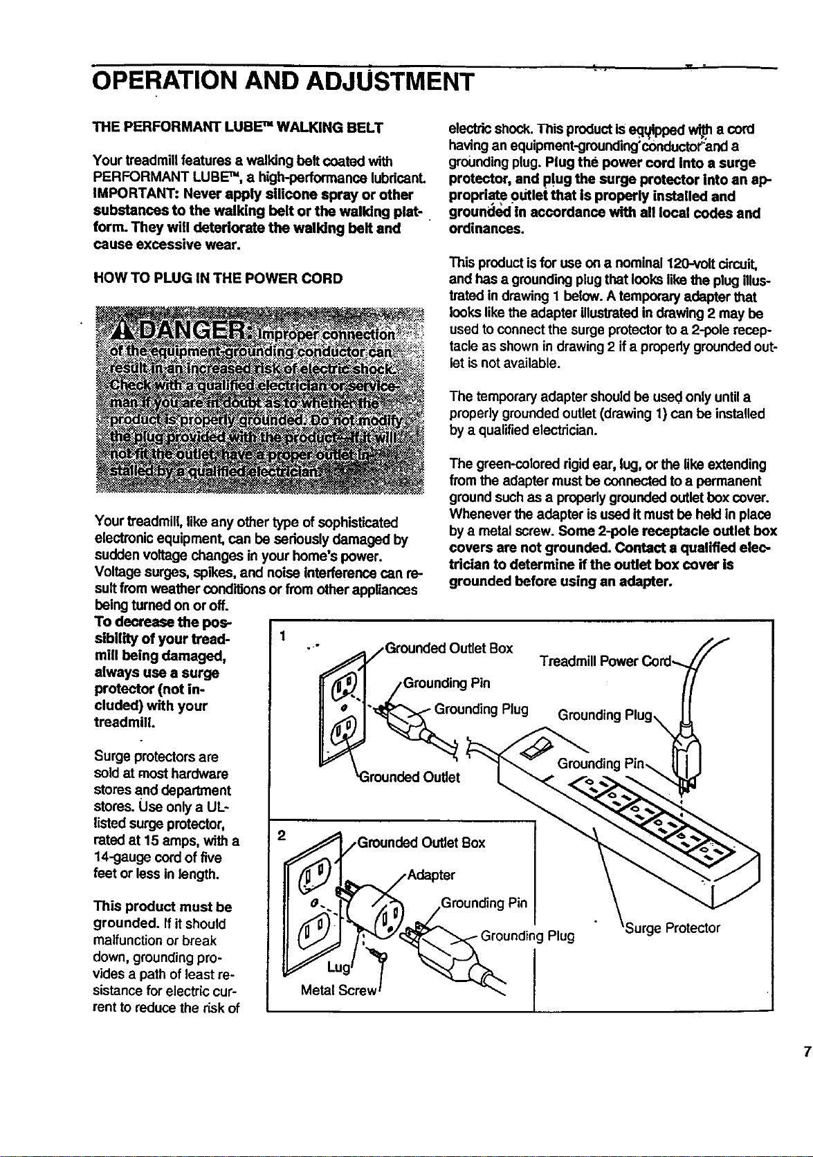
HOWTO PLUG IN THE POWER CORD
electricshock• This productIs eq_ltpped_ a cord
having an equipment-grounding'conductor;anda
groundingplug. Plug the power cord into a surge
protector, and p!ug the surge protector into an ap-
propriat.e .outlet that is properly installed and
grounded In accordance with all local codes and
ordinances.
This productis for use on a nominal 120wolt circuit,
and has a groundingplug that looks like the plug illus-
trated in drawing I below. A temporary adapter that
looks like the adapter Illustrated in drawing 2 may be
used to connect the surge protectorto a 2-pole recep-
tacle as shown in drawing 2 if a pmpedy grounded out-
let is not available.
The temporary adapter should be used only until a
pmpedy groundedoutlet (drawing 1) can be installed
by a qualified electrician.
Your treadmill, like any other type of sophisticated
electronic equipment, can be seriously damaged by
sudden voltage changes in your home's power.
Voltage surges, spikes, and noise Interference can re-
sult from weather conditions or from other appliances
being turned on or off.
To decrease the pos-
sibUity of your tread- 1
mill being damaged,
always use a surge
protector (not in-
cluded) with your
treadmill.
Surge protectorsare
soldat most hardware
stores and department
stores. Use only a UL-
listedsurge protector,
rated at 15 amps, with a
14-gauge cord of five
feet or less in length•
This product must be
grounded. If itshould
malfunction or break
down, groundingpro-
vides a path of least re-
sistance for electric cur-
rent to reduce the risk of
The green-colored dgid ear, lug, or the like extending
from the adapter must be connected to a permanent
ground such as a propady grounded outlet box cover.
Whenever the adapter is used it must be held in place
bya metal screw. Some 2-pole receptacle outlet box
covers are not grounded. Contact a qualified elec-
trician to determine if the outlet box cover is
grounded before using an adapter.
Adapter
L
Metal Screw
Surge Protector
7
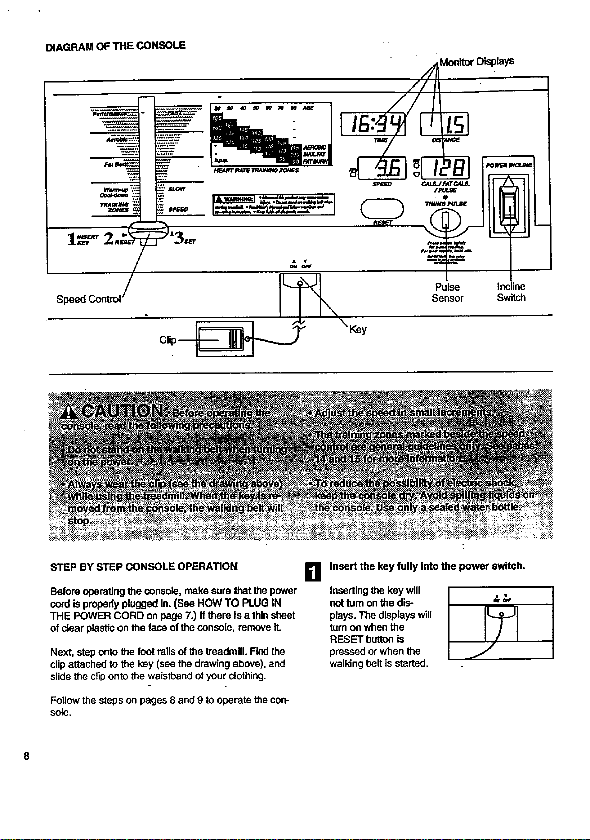
DIAGRAMOFTHECONSOLE
MonitorDisplays
J iL_' _ Pulse Incline
Speed Control _ Sensor Switch
Clip__ =====_e, ._ -_ \Key
STEP BY STEP CONSOLE OPERATION
Before operating the console, make sure that the power
cord is propedy plugged in. (See HOW TO PLUG IN
THE POWER CORD on page 7.) If there is a thin sheet
of clear plastic on the face of the console, remove it.
Next, step onto the foot rails of the treadmill. Find the
clip attached to the key (see the drawing above), and
slide the clip onto the waistband of your clothing.
Follow the steps on pages 8 and 9 to operate the con-
sole.
B
Insert the key fully into the power switch.
Inserting the key will
not tum on the dis-
plays. The displays will
turn on when the
RESET button is
pressed or when the
walking belt is started.
E!
El
B
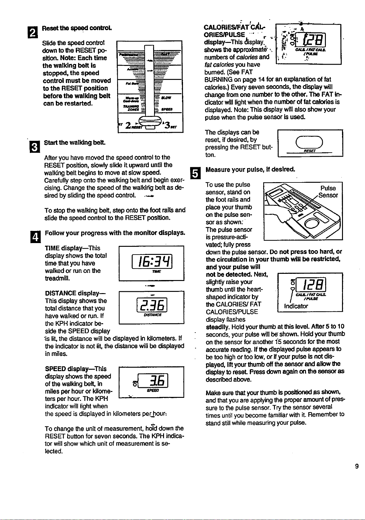
Reaettheapeedcor roL
Slide the speed control
down to the RESET po-
sition. Note: Each time
the walking belt is
stopped, the speed
control must be moved
to the RESET position
before the walking belt
can be restarted.
Start the walking bell
After you have moved the speed control to the
RESET position, slowly slide it upward untilthe
walking belt begins to move at slowspeed.
Carefully step onto the walking belt and begin exer-
cising. Change the speed of the walkirig belt as de-
sired by sliding the speed control. •.--
To stop the walking belt, step onto the foot railsand
slide the speed control to the RESET position.
Follow your progress with the monitor displays.
TIME display--This
display shows the total
time that you have
walked or runon the
treadmill.
I
DISTANCE display--
This display shows the
total distance that you
have walked or run. If
the KPH indicator be-
side the SPEED display
:islit,the distance will be displayed in kilometers. If
the indicator isnot lit, the distance willbe displayed
in miles.
SPEED display--This
display shows the speed
of the walking belt, in
miles per hour or kilome- s_=o
ters per hour. The KPH "
indicatorwill light when
the speed isdisplayed in kilometers per hour:
To change the unitof measurement, hoTddown the
RESET buttonfor seven seconds. The KPH indica-
tor willshow which unit of measurement is se-
lected.
CALO RIF"S/F_ATtC'_t" J ":' _ '--'-- I
ORIES/PULSE ..... r _.1. _",'_,
display--Thls ,splayl1:
shows the approximate' ,. _ _ e._uL,r*re.4u_
numbers of calories and |'__'? z_u=
fat caloriesyou have •
burned. (See FAT
BURNING on page 14 for an explanation of fat
calories.) Every seven seconds, the display will
change from one number tothe other. The FAT in-
dicator will lightwhen the number of fat nalodes is
displayed. Note: This display will also show your
pulse when the pulse sensor is used.
The displays can be
reset, ifdesired, by
pressing the RESET but-
ton.
E]
Measure your pulse, if desired.
To use the pulse
sensor, stand on
the foot railsand
place yourthumb
on the pulsesen-
ser as shown:
The pulsesensor
is pressure-acti-
vated; fully press
Pulse
down the pulse sensor. Do not press too hard, or
the circulation in your thumb will be restricted,
and your pulse will
not be detected. Next,
slightlyraise your _ !,=,_ _']
thumb untilthe heart-
shaped indicatorby
the CALORIES/FAT Indicator
CALORIES/PULSE
display flashes
steadily. Hold yourthumb at this level. After 5 to 10
seconds, your pulse will be shown. Hold your thumb
on the sensorfor another 15 seconds for the most
accurate reading. Ifthe displayed pulse appears to
be ton highor too low, or ifyour pulse is not dis-
played, liftyourthumb off the sensor and allow the
displayto reset. Press down again on the sensor as
describedabove.
Make sure that yourthumb is positionedjasshown,
and that you are applyingthe proper amount of pres-
sure to the pulse sensor.Try the sensor several
times untilyou become familiarwith it. Remember to
stand stillwhile measuringyour pulse.
9
O
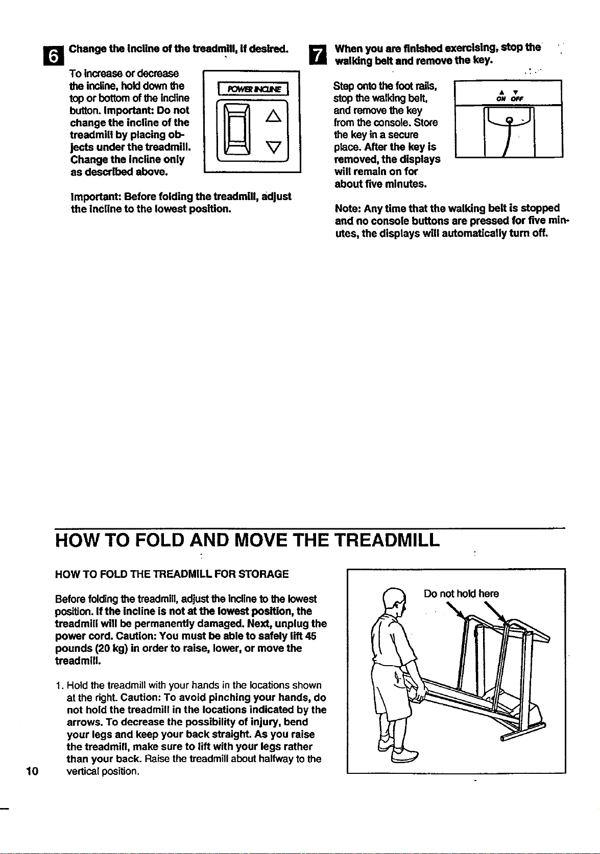
Change the incline of the treadmill, if desired.
To increase or decrease
the incline, hold down the
top or bottom of the incline
button. Important: Do not
change the incline of the
treadmill by placing ob-
jects under the treadmill.
Change the incline only
as described above.
Important: Before folding the treadmill, adjust
the incline to the lowest position.
B Wbon you are finished exerofsing, stop the
walking belt and remove the key.
Step onto the foot rails,
stop the walking belt,
and remove the key
from the console. Store
the key in a secure
place. After the key is
removed, the displays
will remain on for
ON OFF
about five minutes.
Note: Any time that the walking bolt Is stopped
and no console buttons are pressed for five min-
utes, the displays will automatically turn off.
10
HOW TO FOLD AND MOVE THE TREADMILL
HOW TO FOLD THE TREADMILL FOR STORAGE
Before folding the treadmill, adjust the incline to the lowest
position. If the incline is not at the lowest position, the
treadmill will be permanently damaged. Next, unplug the
power cord. Caution: You must be able to safely lift 45
pounds (20 kg) in order to raise, lower, or move the
treadmill.
1. Hold the treadmill with your hands in the locations shown
at the right. Caution: To avoid pinching your hands, do
not hold the treadmill in the locations indicated by the
arrows. To decrease the possibility of injury, bend
your legs and keep your back straight. As you raise
the treadmill, make sure to lift with your legs rather
than your back. Raise the treadmill about halfway to the
vertical position.
Do not hold here
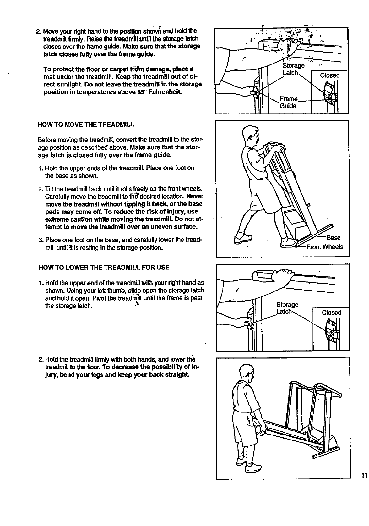
2.Moveyourrighthandtothe_ sho_ and hold the
treadmill firmly. Raise the treadmill untilthe storage latch
doses over the flame guide. Make sure that the storage
latch closes fully over the frame guide.
To protect the floor or carpet f_i_n damage, place a
mat under the treadmill. Keep the treadmill out of di-
rect sunlight. Do not leave the treadmill in the storage
position in temperatures above 85" FahrenheiL
HOW TO MOVE THE TREADMILL
Before moving the treadmill, convertthe treadmill to the stor-
age positionas described above. Make sure that the stor-
age latch is closed fully over the frame guide.
1. Hold the upper ends of the treadmill. Place one foot on
the base as shown,
2. Tilt the treadmillback untilit rollsfreely on the front wheels.
Carefully move the treadmill tothe'desired location. Never
move the treadmill without tipping it back, or the base
pads may come off. To reduce the risk of injury, use
extreme caution while moving the treadmill. Do not at-
tempt to move the treadmill over an uneven surface.
3. Place one foot on the base, and carefully lower the tread-
mill untilit isresting in the storage position.
Latch _ Closed
Frame_
.FrontWheels
HOW TO LOWER THE TREADMILL FOR USE
1. Hold the upper end of the treadmill with your righthand as
shown. Using your leftthumb, slide open the storage latch
and hold t open Pivot the treadm_..lluntil the frame is past
the storage latch. -_-
2. Hold the treadmill firmly with both hands, and lower the
treadmill to the floor. To decrease the possibility of in-
jury, bend your legs and keep your back straighL
Storage
kate_ Closed
11
TROUBLE-SHOOTING
Most treadmill problems can be solved by following the simple steps below. Find the symptom mat ap-
plies, and follow the steps listed. If further assistance is needed, call our toll-free HELPLINE at 1-800-736-
6879, Monday through Saturday, 7 a.m. until 7 p.m. Central Time (excluding holidays).
1. SYMPTOM: THE POWER DOES NOT TURN ON
a. Make sure that the power cord is plugged into a surge protector, and that the surge protector is plugged Into
a properly grounded outlet. (See HOW TO PLUG IN THE POWER CORD on page 7.) Use only a UL-listed
surge protector, rated at 15 amps, with a !4-gauge cord of five feet or less in length.
b. After the power cord has been plugged in, make sure that the key isfully inserted into the console. (See step
1 on page 8.)
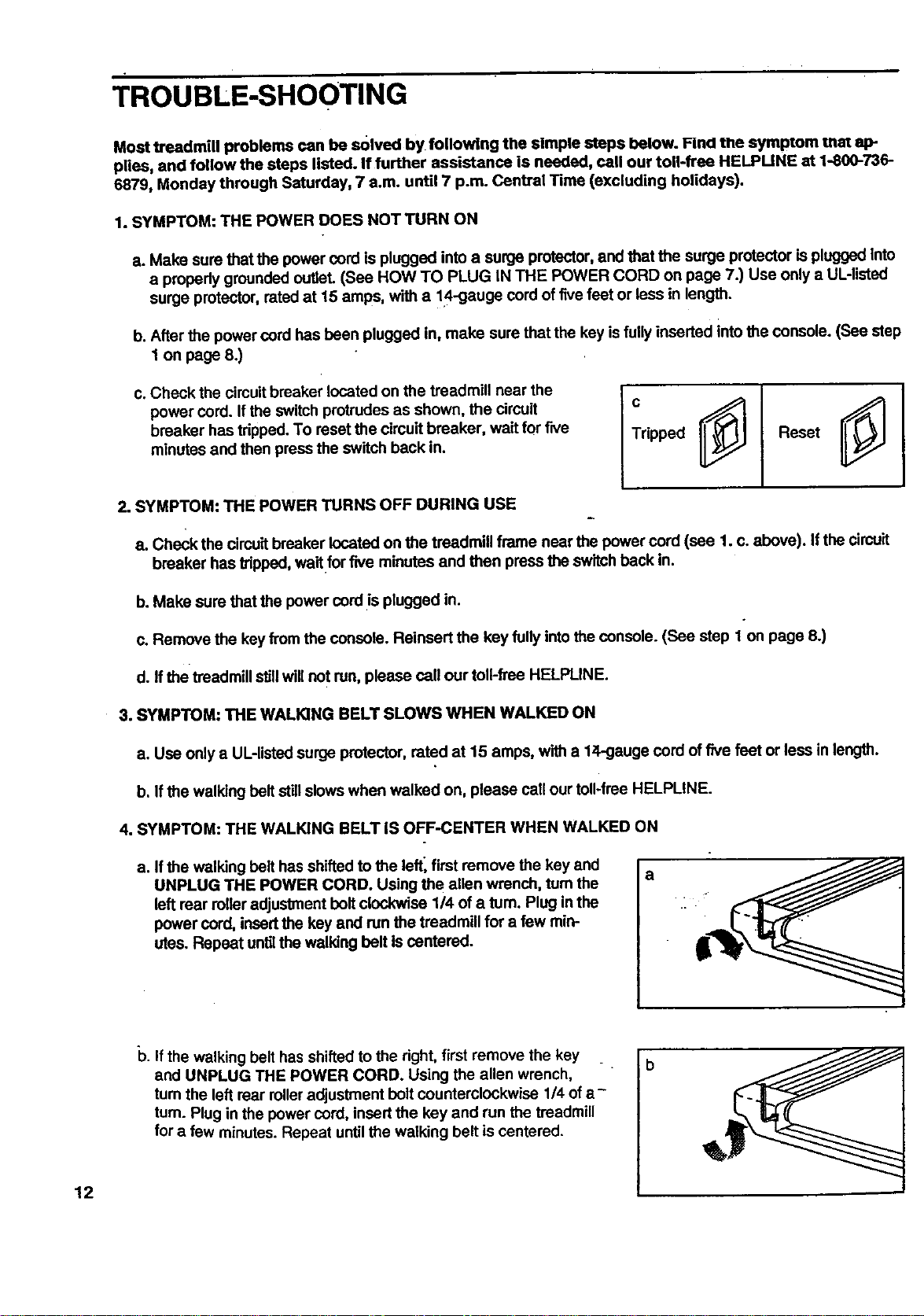
c. Check the circuitbreaker located on the treadmill near the
power cord. Ifthe switch protrudes as shown, the circuit
breaker has tripped. To reset the circuit breaker, wait for five
minutes and then press the switch back in.
Tripped
Reset
2. SYMPTOM: THE POWER TURNS OFF DURING USE
a. Check the circuit breaker located on the treadmill frame near the power cord (see 1. c. above). Ifthe circuit
breaker has thpped, wait for five minutes and then press the switch back in.
b. Make sure that the power cordis plugged in.
c. Remove the key from the console. Reinsert the key fully intothe console. (See step 1 on page 8.)
d. If the treadmill stJUwill not run, please call our toll-free HELPLINE.
3. SYMPTOM: THE WALKING BELT SLOWS WHEN WALKED ON
a. Use only a UL-listedsurge protector, rated at 15 amps, with a lZl,-gaugecord of five feet or less in length.
b. Ifthe walking belt still slows when walked on, please call our toll-free HELPLINE.
4. SYMPTOM: THE WALKING BELT IS OFF-CENTER WHEN WALKED ON
a. If the walking belt has shifted to the left_ first remove the key and
UNPLUG THE POWER CORD. Using the allen wrench, turn the
left rear relier adjustment belt clockwise 114of a rum. Plug in the
power cord, insertthe key and run the treadmill for a few min-
utes. Repeat untilthe walking belt Iscentered.
a
12
b. If the walking belt has shifted to the right, first remove the key _.
and UNPLUG THE POWER CORD. Using the allen wrench,
turn the left rear rolleradjustment bolt counterclockwise 1/4 of a -
tum. Plug in the power cord, insert the key and run the treadmill
for a few minutes. Repeat until the walking belt is centered.

5. SYMPTOM: THE TREADMILL'SITS UNEVENLY ON THE FLOOR
a. Make sure that the six base pads are attached to the treadm (see assemb y step 2 on page,6).
13
CONDITIONING GUIDELINES
accessible carbohydrste ca/ones for energy. Only after
the first few minutes does your body begin to use
stored fat calories for energy. If your goal is to bum fat,
adjustthe speed and inclineof the treadmill until your
heart rate is near one ofthe lower two numbers in your
training zone. Itmay aLsobe helpfulto set the speed
controlon the console to FAT BURN to help you main-
tein the proper intensitylevel. (See page 9.)
Aerobic Exercise
The following guidelines will help you to plan your ex-
ercise program. Remember---these are general guide-
lines only. For more detailed exercise information, ob-
tain a reputable book or consult your physician.
EXERCISE INTENSITY
Whether your goal isto bum fat or to strengthen your
cardiovascular system, the key to achieving the desired
results isto exercise with the proper intensity.The
proper intensity level can be found by using your heart
rate as a guide. The chart below shows recommended
heart rates for fat burning and aerobic exercise.
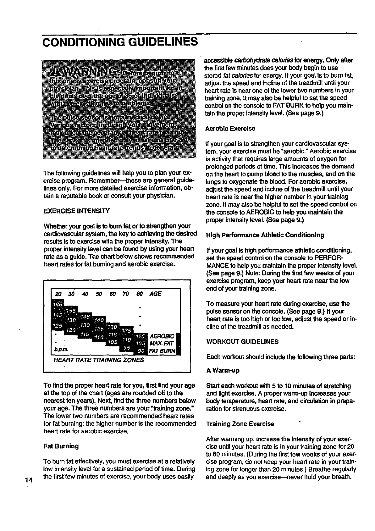
HEART RATE TRAINING ZONES
If your goal isto strengthen your cardiovascular sys-
tem, your exercise mustbe "aerobic." Aerobic exercise
isactivity that requireslarge amounts of oxygen for
prolonged periods of time. This increases the demand
on the heart to pump bloed to the muscles, and on the
lungs to oxygenate the blood. For aerobic exercise,
adjust the speed and incline ofthe treadmill until your
heart rate is near the higher number in your training
zone. It may also be helpful to set the speed control on
the console to AEROBIC to help you maintain the
proper intensity level. (Sea page 9.)
High Performance Athletic Conditioning
If your goal is high peflormance athletic conditioning,
set the speed control on the console to PERFOR-
MANCE to help you maintain the proper intensity level.
(See page 9.) Note: Dudng the first few weeks of your
exercise program, keep your heart rate near the low
end ofyour training zone.
To measure your heart rate during exercise, use the
pulse sensor on the console. (See page 9.) If your
heart rate is too high or too low, adjustthe speed or in-
cline ofthe treadmill as needed.
WORKOUT GUIDEUNES
Each workout should includethe following three parts: .
A Warm-up
14
To find the pioper heart rate for you, first find your age
at the top of the chart (ages are rounded offto the
nearest ten years)_ Next, findthe three numbers below
your age. The three numbers are your .=trainingzone."
The lower two numbers are recommended heart rates
for fat burning; the higher number is the recommended
heart rate for aerobic exercise.
Fat Burning
To burn fat effectively, you mustexercise at a relatively
low intensity level for a sustained peded of time. During
the firstfew minutesof exercise, your body uses easily
Start each workout with 5 to 10 minutes of stretching
and lightexercise. A proper warm-up increases your
body temperature, heart rate, and circulation in prepa-
ration for strenuous exercise.
Training Zone Exercise
After warming up, increase the intensity of your exer-
cise untilyour heart rate is in your training zone for 20
to 60 minutes. (During the first few weeks of your exer-
cise program, do not keep your heart rate in your train-
ing zone for longer than 20 minutes.) Breathe regularly
and deeply as you exercise--never hold your breath.
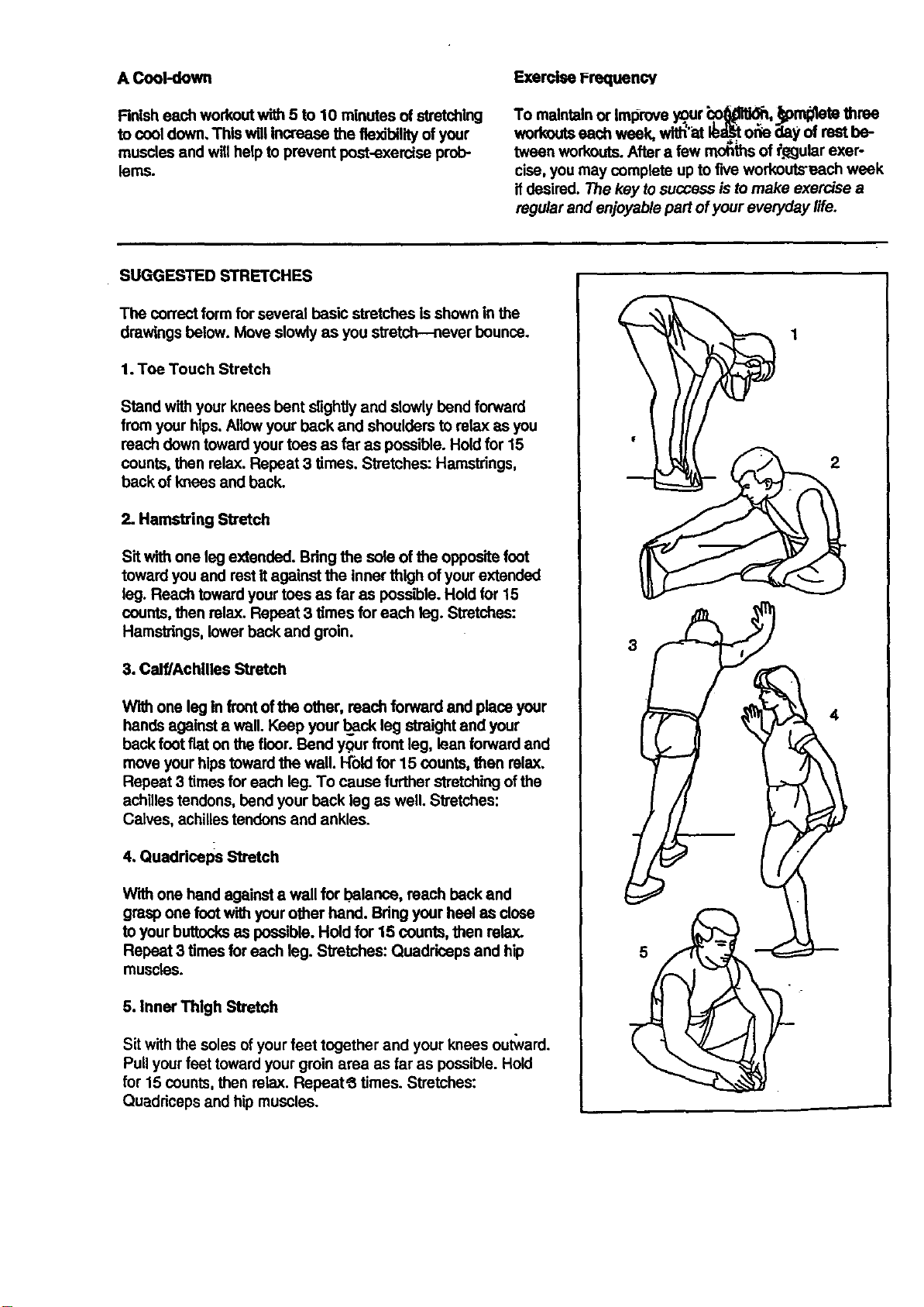
ACool-down
Finisheachworkoutwith5to10minutesofstretching
tocooldown,ThiswUlincreasetheflexibilityofyour
muscles and willhelp to prevent post-exercise prob-
lems.
Exercise PrequencY
To maintainor Iml_roveygur "co_i_, _crn_te three
wortmutseechweek,witl_'atIb_l_t_,ior_ dayofrestbe-
tweenworkouts. After a few mohths of _Qgulerexer-
cise, you may complete up to five workouts'each week
ifdesired. The key tosuccess is tomake exercise a
regularand enjoyable part of your everyday #fe.
SUGGESTED STRETCHES
The correctform for several basic stretches is shown in the
drawings below. Move slowly as you stretch--never bounce.
1. Toe Touch Stretch
Stand with your knees bent slightlyand slowly bend forward
from your hips. Allow your back and shoulders to relax as you
reach down toward your toes as far as possible. Hold for 15
counts, then relax. Repeat 3 times. Stretches: Hamstrings,
back of knees and back.
2. Hamstring Sb'etch
Sit with one leg extended. Bdng the sole of the oppositefoot
toward you and rest itagainst the inner thigh ofyour extended
leg. Reach toward your toes as far as possible. Hold for 15
counts, then relax. Repeat 3 times for each leg. Stretches:
Hamstrings, lowerback and groin.
3. Calf/Achilles Stretch
W'_ one leg in frontofthe other, reach forward and place your
hands against a wall. Keep your back leg straight and your
back foot flat on the floor. Bend your front leg, lean forward and
move your hipstoward the wall. Hold for 15 counts, then relax.
Repeat 3 times for each leg. To cause further stretchingofthe
achilles tendons, bend your back leg as well. Stretches:
Calves, achilles tendons and ankles.
4. Quadriceps Stretch
With one hand against a wall for balance, reach back and
grasp one foot with your other hand. Bring your heel as close
to yourbuttocksas possible. Hold for 15 counts, then relax.
Repeat 3 times for each leg. Stretches: Quadriceps and hip
muscles.
5. Inner Thigh Stretch
Sit with the soles ofyour feet together and your knees ou_ard.
Pull yourfeet toward yourgroin area as far as possible. Hold
for 15 counts, then relax. Repeat_ times. Stretches:
Quaddceps and hip muscles.
3
2
4
_-_.-VE__n THIS EXPLODED DRAWING
!ll._'._OART LIST FROM THE MANUAL
Illl" I"_(pLODED DRAWING and PART LIST for future reference.
1411_11_ ..
I I,_!" l_pecifications are subjectto change without notice. For information about
_,!_P'rI_=greplacementparts, see the back cover of the User's Manual.
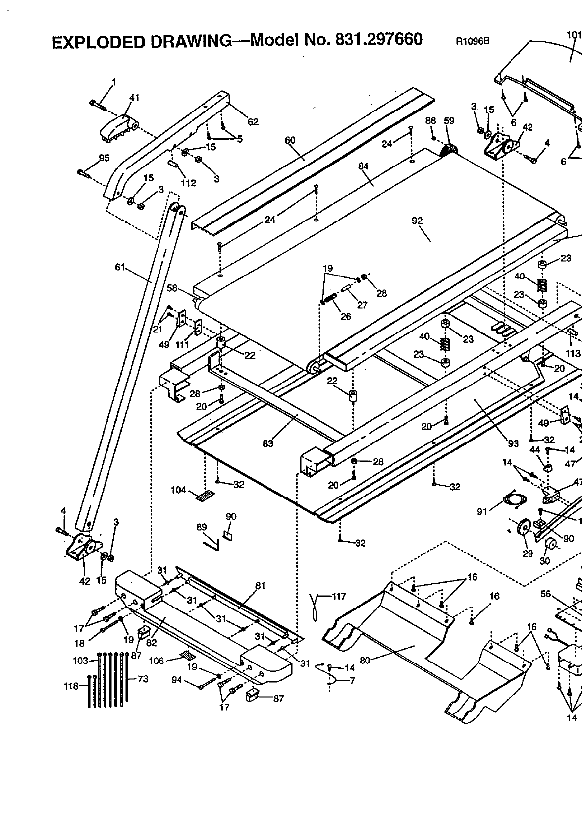
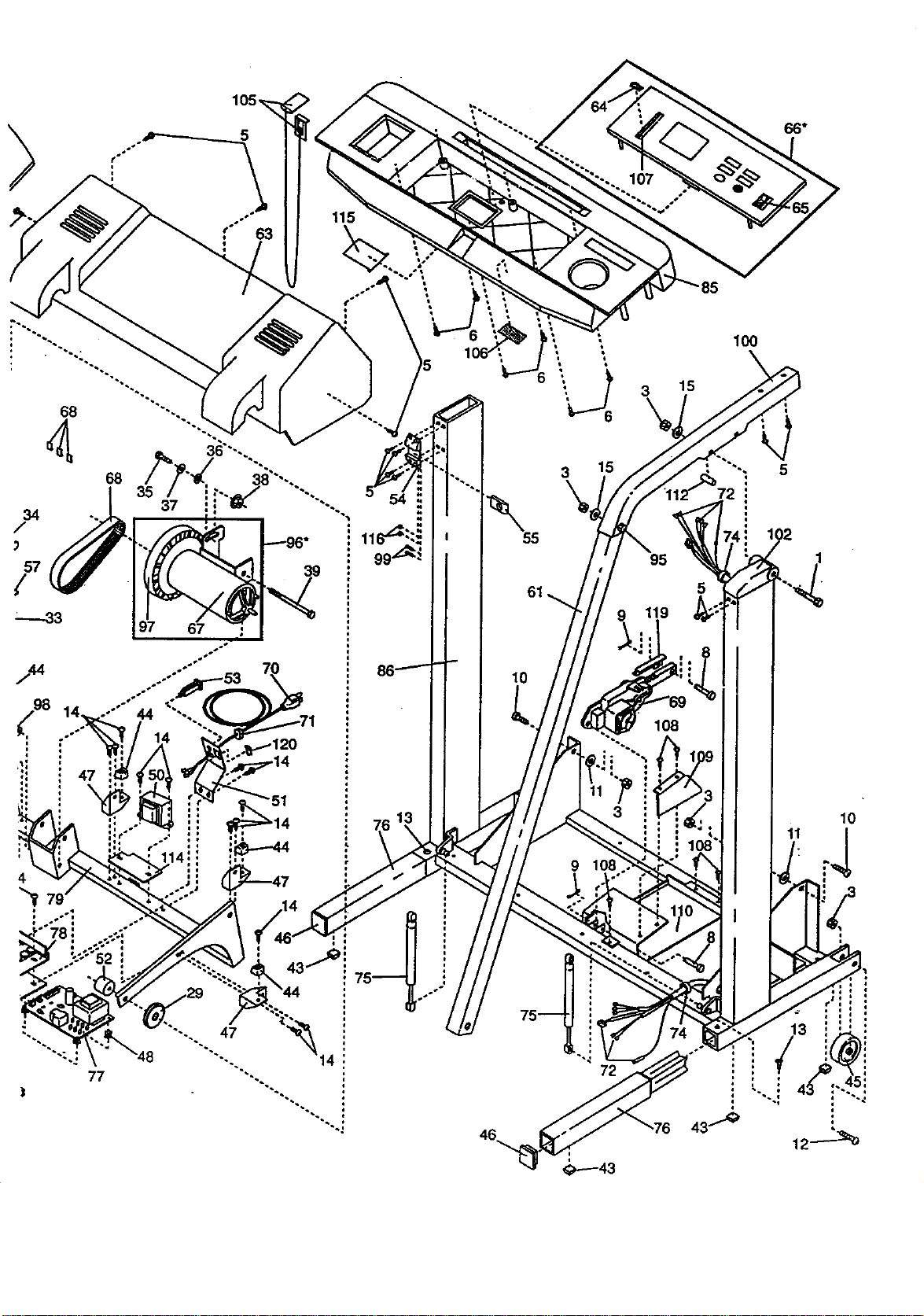
EXPLODED DRAWING--Model No. 831.297660 R1098B 1,
_. 41
15
112
62
84
19
26
88 59
=
i
92
\
6 42
4
3
42
18
83
9O
22 "
16
14
34
/
79
115
39
14
47
\
77
55
61
lO
3 15
95
5
119
IO0
72
10
11
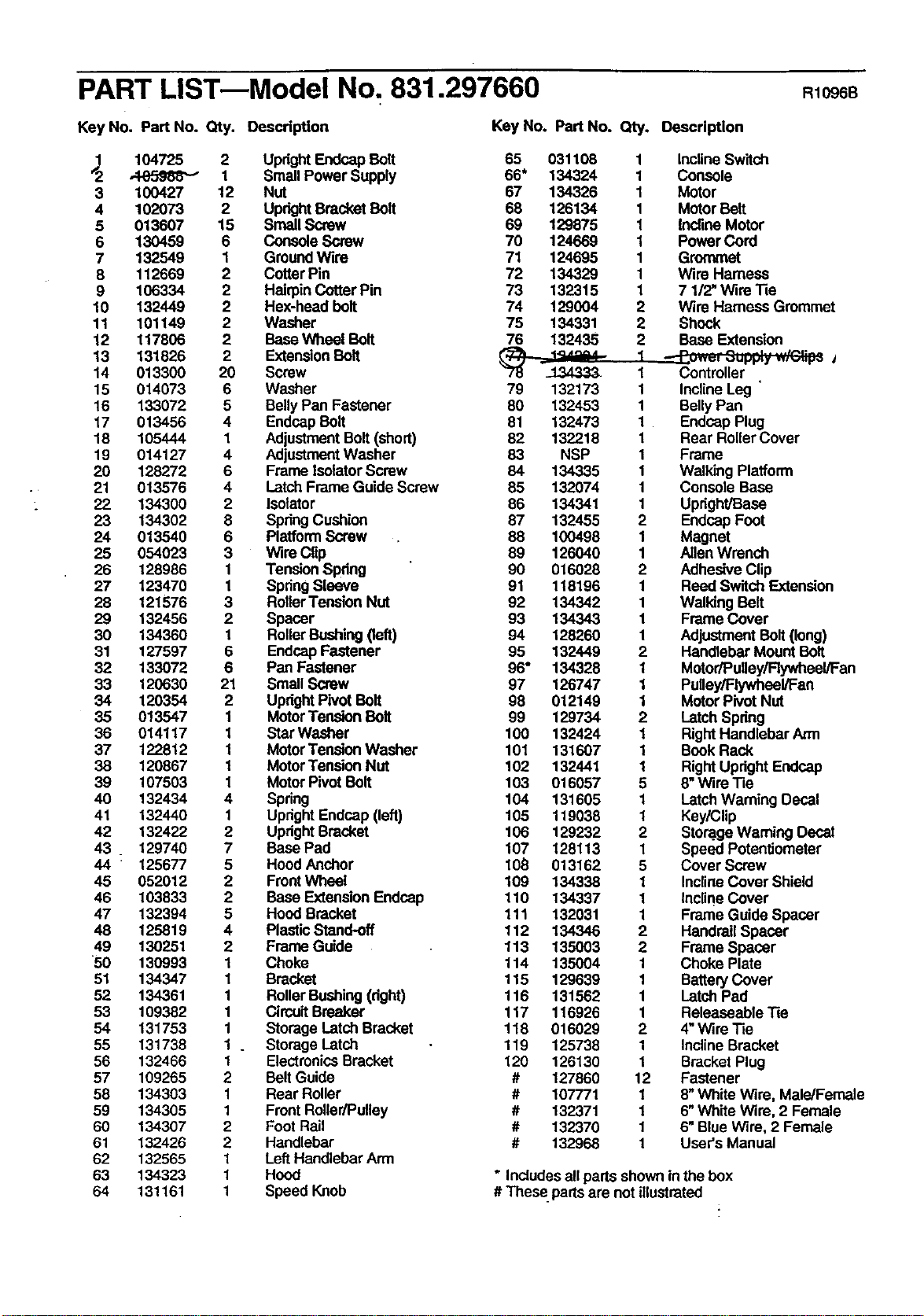
PART LIST--Model No. 831.297660 R1096B
Key No. Part No. Qty. Descdp_on Key No. Part No. Qty. Description
104725 2 UprightEndcap Bolt 65 031108
1 Small Power Supply 66* 134324
3 100427 12 Nut 67 134326
4 102073 2 UprightBracket Bolt 68 126134
5 013607 15 Small Screw 69 129875
6 130459 6 ConsoleScrew 70 124669
7 132549 1 GroundWire 71 124695
8 112669 2 CotterPin 72 134329
9 106334 2 HairpinCotterPin 73 132315
10 132449 2 Hex-head bolt 74 129004
11 101149 2 Washer 75 134331
12 117806 2 BaseWheel Bolt 76 132435
13 131826 2 ExtensionBolt _ .._1'''_"
14 013300 20 Screw "_ _134333.
15 014073 6 Washer 79 132173
16 133072 5 BellyPan Fastener 80 132453
17 013456 4 EndcapBolt 81 132473
18 105444 1 AdjustmentBolt(short) 82 132218
19 014127 4 AdjustmentWasher 83 NSP
20 128272 6 Frame IsolatorScrew 84 134335
21 013576 4 Latch Frame Guide Screw 85 132074
22 134300 2 Isolator 86 134341
23 134302 8 SpringCushion 87 132455
24 013540 6 PlatformScrew 88 100498
25 054023 3 Wire Clip 89 126040
26 128986 1 Tension Spdng 90 016028
27 123470 1 SpringSleeve 91 118196
28 121576 3 RollerTension Nut 92 134342
29 132456 2 Spacer 93 134343
30 134360 1 RollerBushing(left) 94 128260
31 127597 6 EndcapFastener 95 132449
32 133072 6 Pan Fastener 96" 134328
33 120630 21 Small Screw 97 126747
34 120354 2 UprightPivot Bolt 98 012149
35 013547 1 MotorTension Bolt 99 129734
36 014117 1 Star Washer 100 132424
37 122812 1 MotorTension Washer 101 131607
38 120867 1 MotorTension Nut 102 132441
39 107503 1 Motor PivotBolt 103 016057
40 132434 4 Spring 104 131605
41 132440 1 Upright Endcap(left) 105 119038
42 132422 2 UprightBracket 106 129232
43 . 129740 7 BasePad 107 128113
44 • 125677 5 Hood Anchor 106 013162
45 052012 2 Front Wheel 109 134338
46 103833 2 Base ExtensionEndcap 110 134337
47 132394 5 Hood Bracket 111 132031
48 125819 4 PlasticStand-off 112 134346
49 130251 2 Frame Guide 113 135003
50 130993 1 Choke 114 135004
51 134347 1 Bracket 115 129639
52 134361 1 RollerBushing(dght) 116 131562
53 109382 1 CircuitBreaker 117 116926
54 131753 1 StorageLatch Bracket 118 016029
55 131738 1 . Storagelatch 119 125738
56 132466 1 Electronics Bracket 120 126130
57 109265 2 BeltGuide # 127860
58 134303 1 Rear Roller # 107771
59 134305 1 Front Roller/Pulley # 132371
60 134307 2 FootRail # 132370
61 132426 2 Handlebar # 132968
62 132565 1 Left Handlebar Arm
63 134323 1 Hood
64 131161 1 Speed Knob
1 InclineSwitch
1 Console
1 Meter
1 Meter Bait
1 Incline Motor
1 Power Cord
1 Grommet
1 Wire Hamess
1 7 1/2" Wire Tie
2 Wire Harness Grommet
2 Shock
2 Base Extension
1 Controller
1 InclineLeg '
1 BellyPan
1 EndcapPlug
1 Rear RollerCover
1 Frame
1 Walking Platform
1 Console Base
1 Upright/Base
2 EndcapFoot
1 Magnet
1 Allen Wrench
2 AdhesiveClip
1 Reed Switch Extension
1 Walking Belt
1 Frame Cover
1 AdjustmentBolt (long)
2 Handlebar Mount Bolt
1 Motor/PuUey/Rywheel/Fan
1 Pulley/Flywheel/Fan
1 Motor Pivot NUt
2 Latch Spdng
1 RightHandlebar Arm
1 BookRack
1 RightUpright Endcap
5 8"Wire Tie
1 Latch Warning Decal
1 Key/Clip
2 Stora.geWarning Decal
1 Speed Potantiometar
5 Cover Screw
1 InclineCover Shield
1 InclineCover
1 Frame Guide Spacer
2 Handrail Spacer
2 Frame Spacer
1 Choke Plate
1 BatteryCover
1 Latch Pad
1 Releaseable Tie
2 4"Wire Tie
1 InclineBracket
1 Bracket Plug
12 Fastener
1 8"White Wire, Male/Female
1 6"White Wire, 2 Female
1 6" BlueWire, 2 Female
1 User's Manual
* Includesall partsshown inthe box
# These_partsare not illustrated

SEAR8
Model No. 831.297660
QUESTIONS?
If you find that."
• you need help assembling or
operating the PROFORM" 585
TL treadmill
• a part is missing
• or you need to schedule repair
service
call our toll-free HELPLINE
1-800-736-6879
Monday-Saturday, 7 am-7 pm
Central 13me (excluding holidays)
REPLACEMENT
PARTS
If parts become worn and need
to be replaced, call the following
toll-fTee humbler
1-800-FON-PART
(1-800-366-7278)
The model number and serial number of your PROFORM" 585 TL
treadmill are listedon a decal attached to the frame. See the front
cover of this manual tofind the location of the decal.
All replacement pads are available for immediate purchase or
special order when you visityour nearest SEARS Service Center.
To request service or to order pads by telephone, cell the toll-frse
numbers listed at the left.
When requesting help or service, or ordedng parts, please be pre-
pared to provide the followinginformation:
• The NAME OF THE PRODUCT (PROFORM" 585 TL treadmill)
• The MODEL NUMBER OF THE PRODUCT (831.297660)
• The PART NUMBER OF THE PART (see the EXPLODED
DRAWING and PART LIST included in this manual)
• The DESCRIPTION OF THE PART (see the EXPLODED DRAW-
ING and PART LIST included in this manual).
Part No. 132968 FO3315AC R1096B i_dnted in USA © 1996 Sears, Roebuck and Co.