
OWNER’S MANUAL
Thank you for choosing a JL Audio Evolution™ C2 Component System
for your automotive sound system.
These Evolution™ Speakers have been designed and manufactured to
exacting standards in order to ensure years of musical enjoyment in your
vehicle. For maximum performance, we highly recommend that you have
your new speakers installed by an authorized JL Audio dealer. Your
authorized dealer has the training, expertise and installation equipment
to ensure optimum performance from this product. Should you
decide to install the speakers yourself, please take the time
to read this manual thoroughly so as to familiarize yourself
with its installation requirements and setup procedures.
If you have any questions regarding the instructions in this
manual or any aspect of your amplifier’s operation, please contact your
authorized JL Audio dealer for assistance. If you need further assistance,
please call the JL Audio Technical Support Department
at (954) 443-1165 during business hours.
6-inch (150 mm) 2-Way Component System
2 | JL Audio - C2-600 Owner’s Manual
B
F
D
C
A
F
Due to ongoing product development, all specifications are subject to change without notice.
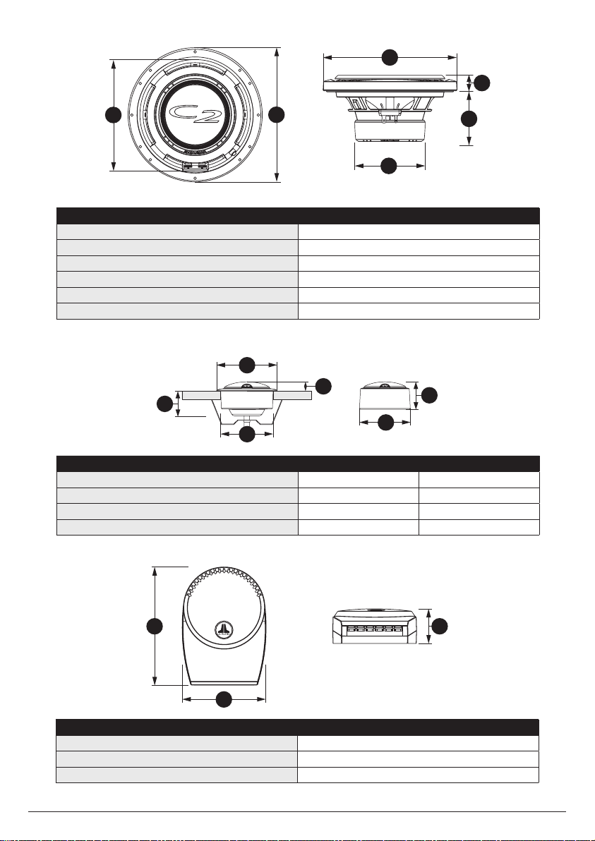
Woofer Physical Dimensions
Frame Outer Diameter (A) 6.21 in. / 157.7 mm
Grille Tray Outer Diameter (B) 6.51 in. / 165.3 mm
Magnet Outer Diameter (C) 3.15 in. / 80.0 mm w/o cover
Frontal Grille Protrusion (D) 0.91 in. / 23 mm
Mounting Hole Diameter (E) 5.00 in. / 127.0 mm
Mounting Depth (F) 2.38 in. / 60.3 mm w/o cover
A
D
C
A
D
B
C
B
A
Crossover Network Physical Dimensions
Height (A) 4.72 in. / 119.9 mm
Width (B) 3.36 in. / 85.3 mm
Depth (C) 1.44 in. / 36.6 mm
Tweeter Fixture Physical Dimensions Flush-Mount Surface-Mount
Fixture Outer Diameter (A) 1.87 in. / 47.5 mm 1.69 in. / 42.9 mm
Fixture Mounting Hole Diameter (B) 1.625 in. / 41.3 mm N/A
Fixture Mounting Depth (C) 0.76 in. / 19.3 mm N/A
Tweeter Frontal Protrusion (D) 0.29 in. / 7.4 mm 0.92 in. / 23.4 mm

2 | JL Audio - C2-600 Owner’s Manual
3
Due to ongoing product development, all specifications are subject to change without notice.
C2-600 SPECIFICATIONS:
Woofer: Injection-molded, Mica-filled, Polypropylene Cone,
Butyl Rubber Surround, 1 in. Voice Coil on Kapton® Former,
Flat, Symmetrical Roll Spider, Ferrite Magnet
Tweeter: 0.75 in. (19 mm) Silk Dome, Ferrofluid Cooling /
Damping, Neodymium Magnet
Crossover Networks: 1st Order Low-Pass Filter, 2nd Order
High-Pass Filter, 3-Position Adjustable Tweeter Level, Premium
Mylar® Capacitors Premium Air-Core Inductors
Continuous Power Handling: 60 Watts
Recommended Amp Power: 15-100 Watts per channel (RMS)
Efficiency: 90.5 dB @ 1W/1m | 96.5 dB @ 1W/0.5m
Sensitivity: 93.5 dB @ 2.83V/1m
Nominal Impedance: 4 ohm
Frequency Response: 59 Hz - 22 KHz ± 3 dB
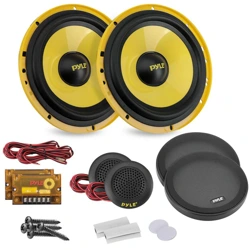
Included Components and Parts:
• Two C2-600cw 6-inch (165 mm) Woofers
• Two C2-075ct 0.75-inch (19 mm) Tweeters
• Two C2-600-XO Crossover Networks
• Two Flush-Mount Tweeter Fixtures
• Two Surface-Mount Tweeter Fixtures
• Two Metal Spring Clips for Tweeter Fixtures
• Two Grille Assemblies
• Two Self-Adhesive JL Audio Nameplates for Grilles
• Twelve #8 x 1.2 inch (30 mm) Sheet Metal Screws
• Four #6 x 1-inch (25 mm) Sheet Metal Screws
• Two 1.18-inch (30 mm) Machine Screws
• Eight Mounting Clips for Woofer Mounting
• Two 4.7 mm Female Crimpable Connectors
• Two 2.8 mm Female Crimpable Connectors
• Two 4.7 Male Crimpable Connectors
• Two 2.8 mm Male Crimpable Connectors
• Twelve Crimpable Spade Connectors
GETTING STARTED
•Turnofftheaudiosystem.Itisalso
advisabletodisconnectthenegative(–)
terminalofyourvehicle’sbatterywhenever
performinginstallationwork.
•Beforecutting,drillingorinsertinganyscrew,
checkclearancesonbothsidesoftheplanned
mountingsurface.Alsocheckforanypotential
obstacles,suchaswindowtracksandmotors,
wiringharnesses,etc.Checkbothsidesofthe
vehicle,manyvehiclesarenotsymmetrical!
•Alwayswearprotectiveeyewear.
SPEAKER PLACEMENT CONSIDERATIONS
Inmostcases,yourspeakerswillbeplacedinto
factoryspeakerlocations.Ifyouhavesomespeaker
mountingflexibility,keepthefollowinginmind:
Lowermountinglocations,suchasthelowerfront
cornerofadoororakick-panelprovidethegreatest
pathlengthdistancesforthesoundemittedbythe
speakers.Forthisreason,theyaregenerallymore
desirablethanhighermountinglocations.Higher
mountinglocationswillusuallyresultinextreme
near-sidesoundstagebiaswhichcompromisesthe
stereolisteningexperience.
4 | JL Audio - C2-600 Owner’s Manual
Amplifier
Output
GETTING STARTED
•Turnofftheaudiosystem.Itisalso
advisabletodisconnectthenegative(–)
terminalofyourvehicle’sbatterywhenever
performinginstallationwork.
•Beforecutting,drillingorinsertinganyscrew,
checkclearancesonbothsidesoftheplanned
mountingsurface.Alsocheckforanypotential
obstacles,suchaswindowtracksandmotors,
wiringharnesses,etc.Checkbothsidesofthe
vehicle,manyvehiclesarenotsymmetrical!
•Alwayswearprotectiveeyewear.
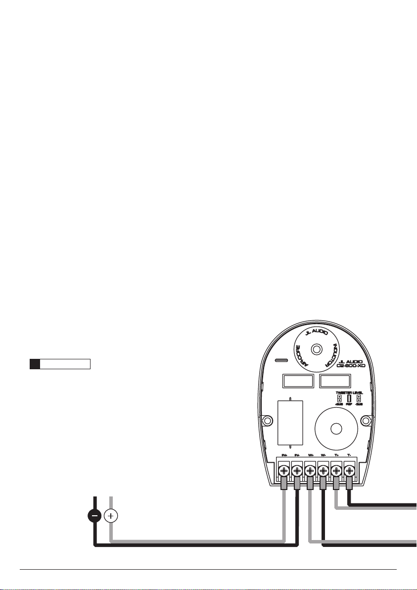
CROSSOVER NETWORK INSTALLATION
ThecrossovernetworkssuppliedwithyourC2
Systemshouldbeinstalledinadrylocationinside
yourvehicle.DONOTINSTALLTHEMINSIDEOF
ADOOR!Doorsoftengetwetontheinside,which
candamageyourcrossovernetworksandcould
potentiallydamageyourentiresoundsystem.The
crossoverscanbescrewedintoasolidsurfaceviatwo
holeslocatedundertheprotectivecoverofthecase.
Toaccesstheseholes,simplysqueezethesidesofthe
coverwhilegentlypullingthecoverawayfromthe
base.Makesurethatyourmountinglocationwillnot
causedamagetowiring,fuellines,brakelinesorany
othervitalcomponentofyourvehicle.Onceyouhave
screwedthecaseinandmadeyourconnections,snap
theprotectivecoverbackintoplace.
WARNING
!!
It is absolutely vital that your component system
is connected as shown in this manual. Failure to
connect the system as shown may result in damage to
your speakers which is NOT covered under warranty.
Do not substitute different crossover networks into
your C2 System. Do not use crossover networks
intended for different C2 models.
TWEETER PROTECTION
TheC2crossovernetworksareequippedwith
anadvancedelectronictweeterprotectioncircuit
designedtominimizethepossibilityoftweeter
failure.Thiselectronicdevicemonitorscurrentgoing
tothetweeterandwilldisconnectthetweeterfrom
thesignalwhenitsensesoverload.Shouldthisoccur
whilelisteningtotheaudiosystem,simplyreducethe
volumeforafewsecondsandtheprotectioncircuit
willresetitselfautomatically.
CROSSOVER NETWORK ADJUSTMENT
Thecrossovernetworkshavebeendesignedto
allowtonaladjustmentstothetweeterlevel.These
adjustmentsmakeitpossibletofine-tuneyoursystem
tosuityourlisteningpreferencesandtocompensate
forvariousspeakermountingapplications.
4 | JL Audio - C2-600 Owner’s Manual
5
Amplifier
Output
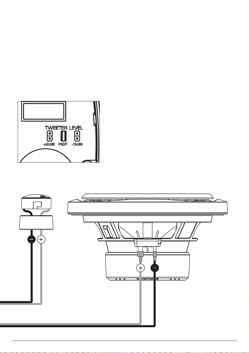
ADJUSTABLE TWEETER LEVEL
C2crossovernetworksalsoprovidethreelevels
oftweeteradjustabilitydesignedtocompensatefor
differentmountinglocations,vehicleinteriorsand
personaltaste.Theselevelsareselectableviaasetof
pinslocatedundertheclearcoverofeachcrossover
case.Werecommendthatyoubeginlisteninginthe
“REF”(Reference)position.Tofindtheoptimum
tonalbalanceinyourinstallation,experimentwith
alternatetweeterlevelsettingsbymovingthepins.It
issafetoswitchjumperswhilethesystemisplaying.
+2dB REF -3dB

6 | JL Audio - C2-600 Owner’s Manual
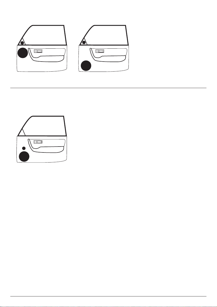
SPEAKER PLACEMENT CONSIDERATIONS
Acomponentsystemgivesyoutheabilitytoplace
thewooferandtweeterseparatelyinyourvehicle
interior.Thiscanbegoodorbad,dependingonhow
it’sdone.Asageneralrule,thetweetersshouldbe
placedrelativelyclosetothewoofersforbesttonal
balanceandmostcoherentimaging(thecloser,the
better).Anyseparationgreaterthan8inches(20cm)
islikelytoresultindegradedsoundquality.
Avoidplacingtweeterswheretheywillbeblocked
byobjectsintheinteriorofthecar(includingseated
occupants).Whenselectingamountinglocation,
lookatbothsidesofthecartomakesurethatthis
locationisclearonbothsides.
Youcanalwaysexperimentwithtweeter
placementbeforecommittingtoafinalmounting
location.Simplyconnecttherestofthesystemand
allowplentyofwirelengthforthetweeters.Using
Velcro®orsimilarmaterial,attachthetweetersin
differentlocationsuntilyoufindtheonewherethey
performbest.
Wooferswillusuallybeplacedintofactory
speakerlocations.Ifyouhavesomewoofermounting
flexibility,keepthefollowinginmind:Lower
mountinglocations,suchasthelowerfrontcorner
ofadoororakick-panelprovidethegreatestpath
lengthdistancesforthesoundemittedbythe
woofer.Forthisreason,theyaregenerallymore
desirablethanhighermountinglocations.Higher
mountinglocationsoftenresultinextremenear-
sidesoundstagebiaswhichcompromisesthestereo
listeningexperience.
6 | JL Audio - C2-600 Owner’s Manual
7
DIAGRAM B: MORE DESIRABLE SPEAKER PLACEMENT
DIAGRAM A: LESS DESIRABLE SPEAKER PLACEMENT

8 | JL Audio - C2-600 Owner’s Manual
InstallasshowninDiagramC(page9).Usethe
suppliedmountingclipsunlessthefactoryholes
alreadyfeaturethreadedinserts.Hand-tightenthe
screwsevenlytoavoidbendingthespeakerframe!
Custom Location:Runspeakerwiretothedesired
mountinglocation.Ifyouarerunningwiresinto
adoor,useexistingfactorywiringbootswhenever
possible.Ifyouaredrillingnewholes,filetheiredges
andinstallrubbergrommetsintoeachhole.Then,
coverthewireswithaprotectivePVCsleeveandrun
themthroughthedoorjamb.Makesurethatthewires
willcleardoorhingesandotherstructuresinthedoor.
Ifyouareunsureaboutanypartofthisprocess,please
contactyourJLAUDIOdealerforinstallationhelp.
WARNING
!!
Double check the clearance for both speakers
before proceeding. Many cars are different from
one side to the other!
Selectanevensurface.Tighteningaspeakeronto
anunevensurfacecandamageit.Usethesupplied
templatetomarkthedesiredmountinglocation.Mark
thecenterandtheoutlineofthemountingholeaswell
asthemountingscrewpositions.Beforedrillingor
cuttingonyourinteriorpanels,useautilityknifetocut
anyfabric,vinylorleatherfromholelocations.These
materialscaneasilybesnaggedbyadrillorasaw,
causingdamagetothepanelandpossiblebodilyinjury.
Drillfour1/8-inch(3mm)holesforthespeaker’s
mountingscrewsatthepositionsyouhavemarked.
Alsodrillapilotholeinthecenterofthespeaker
mountingholeatthistime.Then,usinga
sabersaw,makethecircularcutoutforthespeaker.
Fileanyroughedges.Insertthemountingclipswith
theflatsidetowardsthespeakerasshownin
DiagramD(page9).
Itisabsolutelyvitalthatthespeakerframefitsinto
themountingholecleanly.Thismustbecheckedprior
totighteningthescrews.Donotforcetheframeintoa
holethatistoosmall.Donottightenthespeakeronto
anunevensurface.Thiswilldamageyourspeakers.
Thespeakershouldalsofitsothatairdoesnotleak
aroundthemountingflange.Airleakswillcausea
severedegradationinsoundquality.Sealanyairleaks
withanautomotive-gradesealantmaterial.
SPEAKER INSTALLATION
Thespeakershouldbeinstalledinoneofthe
followingwaysdependingonlocation:
Factory Location:Ifyouwillbeusingthefactory
speakerwires,itmaybenecessarytochangethe
terminations.Thismaybeaccomplishedbyusingan
adaptorplugorsimplybycuttingthefactoryconnector
offandusingthesuppliedcrimpconnectorsto
terminatethespeakerwires.Thelargeconnectorisfor
thepositiveterminalandthesmallconnectorisforthe
negativeterminalofeachC2-600.
Youmayalsochoosetorunnewspeakerwires...
Runspeakerwiretothedesiredmounting
locations.Ifyouarerunningwiresintoadoor,use
existingfactorywiringbootswheneverpossible.If
youaredrillingnewholes,filetheiredgesandinstall
rubbergrommetsintoeachhole.Wiresshouldthen
becoveredwithaprotective,flexiblePVCsleeveand
thenrunthroughthedoorjamb.Makesurethatthe
wireswillcleardoorhingesandotherstructuresin
thedoor.Ifyouareunsureaboutanypartofthis
process,pleasecontactyourJLAudiodealerfor
installationhelp.
WARNING
!!
Double check the clearance for both speakers
before proceeding. Many cars are different from
one side to the other!
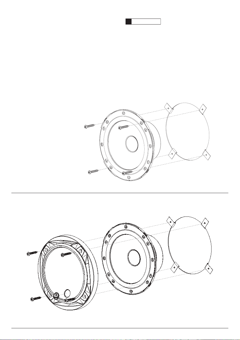
Yournewspeakershavebeendesignedtoinstall,
withoutmodifications,intomostvehiclesthataccept
a6-inch(165mm)speaker.Mostfactory6-inch
speakersusefourmountingscrewswhichwilllineup
withthemountingholesonyourC2-600speakers.
Othersusea3-holemountingsystemwhichis
accommodatedbyaseparatesetofmountingholes
ontheframesofyourC2-600speakers.
Itisabsolutelyvitalthatthespeakerframe
fitsintothemountingholecleanly.Thismustbe
checkedpriortotighteningthescrews.Donot
forcetheframeintoaholethatistoosmall.Do
nottightenthespeakerontoanunevensurface.
Thiswilldamageyourspeakers.Thespeaker
shouldalsofitsothatairdoesnotleakaround
themountingflange.Airleakswillcauseasevere
degradationinsoundquality.Sealanyairleaks
withanautomotive-gradesealantmaterial.
8 | JL Audio - C2-600 Owner’s Manual
9
Connectthespeakerwires,observingcorrect
polarity,andinstallthespeakerandgrilleassembly
asshowninDiagramD(below).Hand-tightenthe
screwsevenlytoavoidbendingthespeakerframe!
TheincludedJLAudiologonamebadgesshould
beaffixedtothecircularindentedareainthelower
partofeachgrilleassembly.Ifthegrilleassemblyis
notused,theJLAudiologobadgescanbeaffixed
elsewhereascreativeadditionstoyourinstallation.
DIAGRAM D: CUSTOM LOCATION WOOFER INSTALLATION
DIAGRAM C: FACTORY LOCATION WOOFER INSTALLATION
WARNING
!!
Hand-tighten the screws evenly in a criss-cross
pattern to avoid bending the speaker frame or
stripping the mounting clips.

10 | JL Audio - C2-600 Owner’s Manual
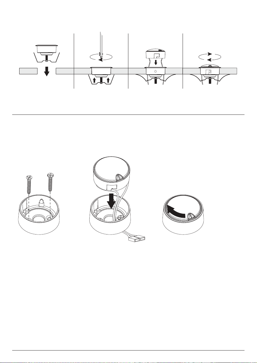
Surface-Mount:Inthisapplication,youwillnot
needtocutlargeholesinyourvehicle’spanelsforthe
tweeters.Youwillonlyneedtodrillaholeforthewires
andtwosmallerholesforthemountingscrews.This
applicationisusefulwhenmountingthetweeterstoa
panelthathasinsufficientclearancebehinditforthe
tweeter’smagnetstructure.
Usingthefixtureasatemplate,markthescrewhole
locationsandalocationinthecenterofthefixturefor
thewirehole.Removethefixtureanddrillpilotholes
forthescrewsanda1/8-inch(3mm)forthewires.Use
thesupplied#6x1-inchsheetmetalscrewstosecure
thefixtureasshowninDiagramF(hand-tighten).Run
thetweeter’swiresthroughthehole,makeappropriate
connectionsandinsertthetweeterintothemounting
cup.Pushthetweeterdownandrotateitclockwiseto
lockitintoplace.
TWEETER INSTALLATION
First,runspeakerwiresfromthetweeteroutputof
thecrossover(seediagramsonpage5)tothedesired
tweetermountinglocations,observingthesame
precautionsasmentionedinthewooferinstallation
section.Terminatethewireswiththesupplied2.8
mmand4.7mmmalecrimpableconnectors.
TWEETER FIXTURE INSTALLATION
Thedometweeterssuppliedwithyour
C2-600systemhavebeendesignedformaximum
mountingversatility.Therearetwoprimary
methodsbywhichthetweeterscanbemountedin
yourvehicle:
Flush-Mount:Fortweeterintegrationinaclean,
unobtrusivemanner,youwillusethesupplied
flush-mountcups.Thiscompactmountingfixtureis
installedusingthemethodillustratedinDiagramE
andrequiresamountingholewithadiameterof1.625
in.(41.28mm).
Atleast0.76in.(19.3mm)ofclearanceisrequired
behindthemountingsurfaceofthetweeterforthe
springclipsand1.18-inchmachinescrewsusedin
mountingthefixture.Itmaybenecessaryinsome
limiteddepthapplicationstocutdownthelength
ofthemachinescrew,ortouseashorterscrew(not
supplied).Hand-tightenthemachinescrewuntilthe
fixtureissecure.Runthetweeter’swiresthroughthe
hole,makeappropriateconnectionsandinsertthe
tweeterintothemountingcup.Pushthetweeterdown
androtateitclockwisetolockitintoplace.
10 | JL Audio - C2-600 Owner’s Manual
11
DIAGRAM E: FLUSHMOUNT TWEETER INSTALLATION
DIAGRAM F: SURFACEMOUNT TWEETER INSTALLATION

LIMITED WARRANTY AUTOMOTIVE SPEAKER SYSTEMS USA
JLAUDIOwarrantsthesespeakers(andcrossovernetworks,whereapplicable)tobefreeofdefectsin
materialsandworkmanshipforaperiodofone (1) year.
Thiswarrantyisnottransferableandappliesonlytotheoriginalpurchaserfromanauthorized
JLAUDIOdealer.Shouldservicebenecessaryunderthiswarrantyforanyreasonduetomanufacturing
defectormalfunction,JLAUDIOwill(atitsdiscretion),repairorreplacethedefectiveproductwithnewor
remanufacturedproductatnocharge.Damagecausedbythefollowingisnotcoveredunderwarranty:accident,
misuse,abuse,productmodificationorneglect,failuretofollowinstallationinstructions,unauthorizedrepair
attempts,misrepresentationsbytheseller.Thiswarrantydoesnotcoverincidentalorconsequentialdamages
anddoesnotcoverthecostofremovingorreinstallingtheunit(s).Cosmeticdamageduetoaccidentornormal
wearandtearisnotcoveredunderwarranty.
Anyapplicableimpliedwarrantiesarelimitedindurationtotheperiodoftheexpresswarrantyasprovided
hereinbeginningwiththedateoftheoriginalpurchaseatretail,andnowarranties,whetherexpressorimplied,
shallapplytothisproductthereafter.Somestatesdonotallowlimitationsonimpliedwarranties,therefore
theseexclusionsmaynotapplytoyou.Thiswarrantygivesyouspecificlegalrights,andyoumayalsohave
otherrightswhichvaryfromstatetostate.
If you need service on your JL AUDIO product:
AllwarrantyreturnsshouldbesenttoJLAUDIOfreightprepaidthroughanauthorizedJLAUDIO
dealerandmustbeaccompaniedbyproofofpurchase(acopyoftheoriginalsalesreceipt.)Direct
returnsfromconsumersornon-authorizeddealerswillberefusedunlessspecificallyauthorizedby
JLAUDIOwithavalidreturnauthorizationnumber.Warrantyexpirationonproductsreturned
withoutproofofpurchasewillbedeterminedfromthemanufacturingdatecode.Coveragemaybe
invalidatedasthisdateisprevioustopurchasedate.Returnonlydefectivecomponents.Ifonespeaker
failsinasystem,returnonlythatspeakercomponent,nottheentiresystem.Non-defectiveitems
receivedwillbereturnedfreight-collect.Customerisresponsibleforshippingchargesandinsurance
insendingtheproducttoJLAUDIO.Freightdamageonreturnsisnotcoveredunderwarranty.
For Service Information in the U.S.A. please call
JL Audio Customer Service: (954) 443-1100
9:00 AM – 5:30 PM (Eastern Time Zone)
JL Audio, Inc
10369 North Commerce Pkwy.
Miramar, FL 33025
International Warranties:
Products purchased outside the United States of America are covered only
by that country’s distributor and not by JL Audio, Inc.
Printed in China C2-600-02102009