Loading ...
Loading ...
Loading ...
ASSEMBLY
Make sure that the power cord is unplugged. Assembly requires two persons. Set the treadmill in a cleared
area and remove all packing materials. Do not dispose of the packing materials until assembly iscompleted. Note:
The underside of the treadmill walking belt is coated with high-performance lubricant. During shipping, a small
amount of lubricant may be transferred to the top of the walking belt or the shipping carton. This is a normal con-
dition and does not affect treadmill performance. If there is lubricant on top of the walking belt, simply wipe off the
lubricant with a soft cloth and a mild, non-abrasive cleaner.
Assembly requires the included allen wrenches _ and your own phillips screwdriver (_]_======_
wire cutters *-__-> ,and adjustable wrench _ .
Use the drawings below to identify the assembly hardware. The number in parentheses below each drawing is
the key number of the part, from the PART LIST on pages 26 and 27. The number after the parentheses shows
the quantity needed for assembly. Note: If a part is not in the parts bag, check to see if it is preattached to one of
the parts to be assembled, if a part is missing, call toll=free 1=888=533=1333.
Nut (20)-4
Washer(71)-4
Base Pad Screw (40)-4
1" Screw (88)-4
Extension Screw (80)-4
Screw (95)-8
1 3/4" Bolt (76)-2
Wheel Bolt (90)-2
3" Bolt (86)-2
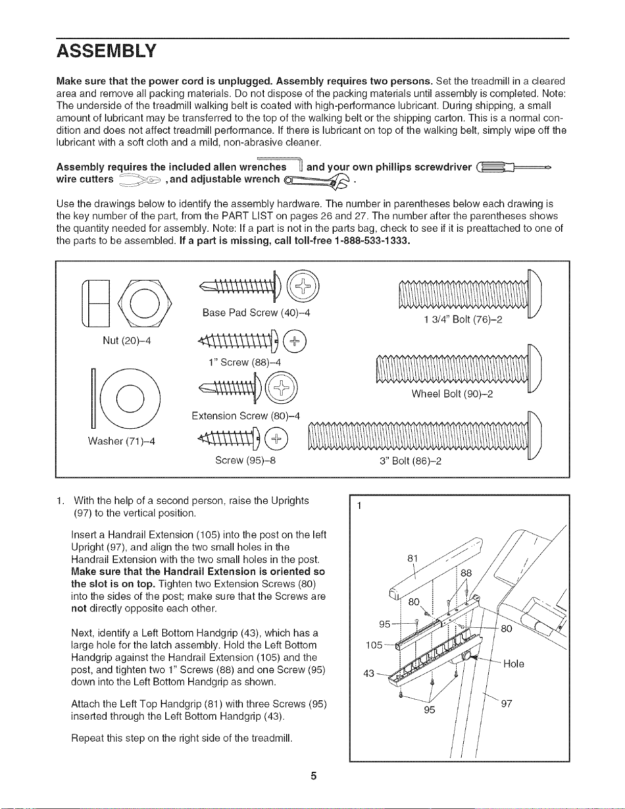
With the help of a second person, raise the Uprights
(97) to the vertical position.
Insert a Handrail Extension (105) into the post on the left
Upright (97), and align the two small holes in the
Handrail Extension with the two small holes in the post.
Make sure that the Handrail Extension is oriented so
the slot is on top. Tighten two Extension Screws (80)
into the sides of the post; make sure that the Screws are
not directly opposite each other.
Next, identify a Left Bottom Handgdp (43), which has a
large hole for the latch assembly. Hold the Left Bottom
Handgrip against the Handrail Extension (105) and the
post, and tighten two 1" Screws (88) and one Screw (95)
down into the Left Bottom Handgdp as shown.
Attach the Left Top Handgrip (81) with three Screws (95)
inserted through the Left Bottom Handgdp (43).
Repeat this step on the right side of the treadmill.
43
81
95
Hole
97
Loading ...
Loading ...
Loading ...